POWERTEX PBC-S1 User manual

1
POWERTEX
Beam Clamp PBC-S1
GB Instruconforuse
FR Manueld’ulisaon
User Manual
UMPBC20190520FR
!

2
Read through these user instructions carefully before using the beam
clamp. Improper operation may lead to hazardous situations!
The POWERTEX beam clamp is designed for mounting on the lower
ange of an I-beam for suspending a load or lifting device. The beam
clamp is xed in position with a right-hand and left-hand threaded rod
in a scissor construction.
Safety rules
• The beam on which the clamp is to be mounted must be checked
by a competent person. This person must assess the beam’s load
bearing capacity and xings and its suitability for the purpose.
• Check the beam clamp before use for function and any cracking,
deformation or wear.
• Load on the beam clamp must not exceed the maximum load indi-
cated on the rating plate.
• The beam clamp must only be used for beams with a ange width
within the range indicated on the rating plate.
• The clamp must be xed to the beam above the load’s centre of
gravity.
• Dynamic stresses must be avoided.
• Inclined pulls are not permitted.
• Working temperature: -10°C to +50°C.
Dimensioned sketch
Technical data
Art No Model WLL I beam width rangeA max. B min. B max. C D E F min. F max. G min. H Weight
(ton) (mm) (mm) (kg)
16.02PBCS1010 PBC-S1 180-240 270 183 370 94 4 198 100 154 22 20 3,5
16.02PBCS1020 PBC-S1 280-240 270 183 370 102 6 198 100 154 22 20 4,5
16.02PBCS1030 PBC-S1 390-330 355 243 500 132 8 263 148 219 46 22 9,5
16.02PBCS1050 PBC-S1 590-330 355 243 500 142 10 263 148 219 43 28 11
16.02PBCS1100 PBC-S1 10 90-350 364 269 521 180 12 285 165 239 51 38 16
Safety factor: 4:1
Static test coefcient: WLL x 1,5
Generally according to EN 13155
Mounting
Open the beam clamp by unscrewing the threaded rod with the handle
sufciently to allow the clamp to enclose the beam. Screw up the
beam clamp centrally over the load’s centre of gravity. Make sure the
arms on the beam clamp have a secure grip on the beam ange. (See
dimensioned drawing).
The load or suspension hook on the lifting device must hang centrally
from the bowed centre of the suspension bolt.
Continuous maintenance - lubrication
Bearings and threaded sections and the surface of the suspension bolt
in contact with the load hook must be cleaned and lubricated as ne-
cessary. Periodic checks must normally be carried out yearly to detect
and remedy any faults. Damaged parts must be replaced with original
POWERTEX parts.A set of threaded rods and nuts can be ordered
through your dealer.
Contact your dealer for spare parts in general.
Replacing the threaded rod.
1 Open the beam clamp as far as it will go.
2 Knock the locking pin out of the handle.
3 Completely unscrew the threaded rod.
4 Remove the old nuts by pressing them out of the beam clamp’s
arms. Dismantle and clean the spacers.
5 Mount the new nuts together with the spacers.
6 Oil and screw the new threaded rod into the nuts. Make sure both
threads go in simultaneously.
7 Screw up until the handle can be mounted and lock with the locking
pin.
8 Continue screwing to the desired position.
Instruction Grey Label
To change your new POWERTEX Beam Clamp to Black Line:
If the product should be used in dark environments, add the grey label
on the product’s name plate like this.
The data on the nameplate should ALWAYS be visible, and must NOT
be covered.
If the product is modied in any way, or if it is combined with a
non-compatible product / component, AxInter Lifting Solutions take
no responsibility for the consequences in regard to the safety of the
product
POWERTEX Beam Clamp PBC-S1 1 – 10 ton
Assembly / Instruction for use (GB) (Original instructions)

2 3
Lire attentivement ce manuel d’utilisation avant de se servir de
l’attache de poutre. Toute opération incorrecte peut entraîner des
situations dangereuses !
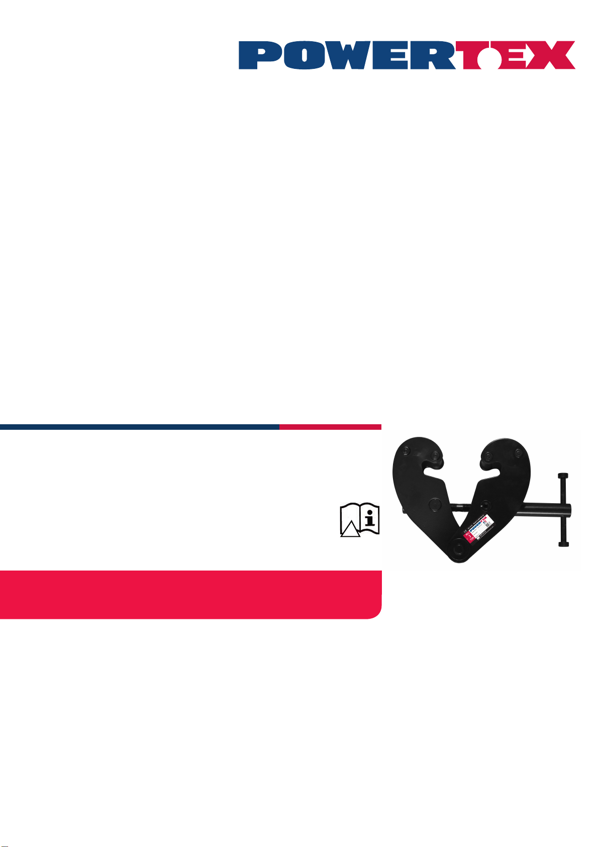
L’attache de poutre POWERTEX est conçue pour le montage sur
la bride inférieure d’une poutre en I en vue de la suspension d’une
charge ou d’un engin de levage. L’attache de poutre est xée en
position au moyen d’une tige à letage à gauche et à droite dans une
construction en ciseaux.
Règles de sécurité
• Une personne compétente doit vérier la poutre sur laquelle
l’attache doit être montée. Cette personne doit évaluer la capacité por-
tante et les xations de la poutre ainsi que leur adéquation à cette n.
• Vérier avant utilisation le bon fonctionnement de l’attache de
poutre et rechercher toute ssure, déformation ou usure.
• La charge sur l’attache de poutre ne doit pas excéder la charge
maximale indiquée sur la plaque signalétique.
• L’attache de poutre doit seulement être utilisée pour des poutres
ayant une largeur de bride comprise dans la plage indiquée sur la
plaque signalétique.
• L’attache de poutre doit être xée à la poutre au milieu, au-dessus
du centre de gravité de la charge.
• Il faut éviter les contraintes dynamiques.
• Les tirants obliques ne sont pas autorisés.
• Température de fonctionnement : de -10°C à +50°C.
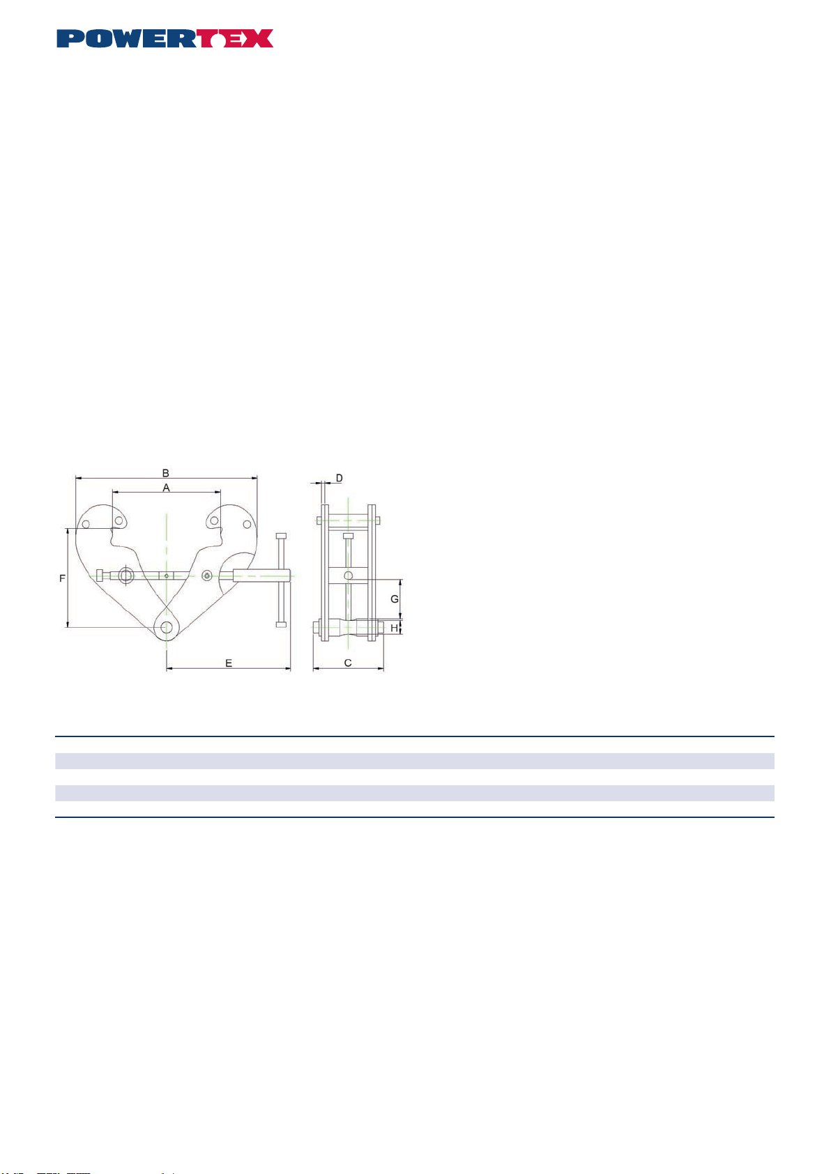
Croquis côté
Données techniques
Réf. Modéle CMU Plage d’ouverture
de la poutre en I A max. B min. B max. C D E F min. F max. G min. H Poids
(Tonnes) (mm) (mm) (kg)
16.02PBCS1010 PBC-S1 180-240 270 183 370 94 4 198 100 154 22 20 3,5
16.02PBCS1020 PBC-S1 280-240 270 183 370 102 6 198 100 154 22 20 4,5
16.02PBCS1030 PBC-S1 390-330 355 243 500 132 8 263 148 219 46 22 9,5
16.02PBCS1050 PBC-S1 590-330 355 243 500 142 10 263 148 219 43 28 11
16.02PBCS1100 PBC-S1 10 90-350 364 269 521 180 12 285 165 239 51 38 16
Facteur de sécurité : 4:1.
Coefcient d’épreuve statique : WLL x 1,5.
Généralement selon la norme EN 13155.
Montage
Ouvrir l’attache de poutre en dévissant la tige à letage à l’aide de la
poignée de façon sufsante pour permettre à l’attache d’entourer la
poutre. Revisser l’attache de poutre au milieu au-dessus du centre de
gravité de la charge. Veiller à ce que les pattes de l’attache de poutre
assurent une bonne prise de la bride de la poutre. (Voir le plan côté).
Le crochet de levage ou de suspension de l’engin de levage doit
pendre au milieu, à partir du centre échi du boulon de suspension.
Maintenance continue - lubrication
Les roulements et sections letées ainsi que la surface du boulon de
suspension en contact avec le crochet de levage doit être nettoyé
et lubrié si nécessaire. Il faut en principe effectuer des vérications
périodiques chaque année pour détecter tout défaut et y remédier. Les
pièces endommagées doivent être remplacées par des pièces d’ori-
gine POWERTEX. Vous pouvez commander un jeu de tiges letées et
d’écrous auprès de votre distributeur.
Contactez votre distributeur pour les pièces de rechange en général.
Remplacement de la tige letée.
1 Ouvrir l’attache de poutre à son maximum.
2 Faire sortir la goupille de sûreté de la poignée en la tapotant.
3 Dévisser entièrement la tige letée.
4 Retirer les anciens écrous en appuyant dessus pour les faire sortir
des pattes de l’attache de poutre. Démonter et nettoyer les entretoises.
5 Remonter les écrous neufs avec les entretoises.
6 Huiler et visser la tige letée neuve dans les écrous. S’assurer de
l’entrée simultanée des deux letages.
7 Revisser jusqu’à ce que la poignée puisse être montée et verrouiller
au moyen de la goupille de sûreté.
8 Continuer de visser jusqu’à la position souhaitée.
Instructions étiquette grise
Pour changer votre nouvelle attache de poutre POWERTEX en ”Black
Line” :
Pour une utilisation du produit dans un environnement sombre, ajouter
l’étiquette grise sur la plaque signalétique du produit comme ceci.
Les données sur la plaque signalétique doivent TOUJOURS être visi-
bles, et ne doivent PAS être recouvertes.
Si le produit est modié de quelque manière que ce soit, ou s’il est
combiné à un produit / composant non compatible, AxInter Lifting
Solutions n’assume aucune responsabilité quant aux conséquences en
matière de sécurité du produit.
Attache de poutre POWERTEX PBC-S1 1 – 10 tonnes
Montage / Manuel d’utilisation (FR)

4
Product compliance and conformity
SCM Citra OY
Juvan Teollisuuskatui 25 C
02920 Espoo
Finland
www.powertex-products.com

45
CERTEX Lifting KnowHow app
Download The Lifting KnowHow app’en from the App Store / Google play!
The App has the following features:
- Load charts for different types of lifting slings
- Protractor for measuring sling angles
- Instructions for safe use of a selection of lifting gear
- Built-in gps function that nds the Lifting Solutions Group ofce closest to
your position.
- And a lot more.
The Lifting KnowHow is a unique knowledge transfer programme.
CertMax+
The CertMax+ system is a unique leading edge certication management
system which is ideal for managing a single asset or large equipment port-
folio across multiple sites. Designed by the Lifting Solutions Group, to deliver
optimum asset integrity, quality assurance and traceability, the system also
improves safety and risk management levels.
User Manuals
You can always nd the valid and updated User Manuals on the web.
The manual is updated continuously and valid only in the latest version.
NB! The English version is the Original instruction.
The manual is available as a download under the following link:
www.powertex-products.com/manuals
!

www.powertex-products.com
Canary Islands
Table of contents
Languages:
Other POWERTEX Industrial Equipment manuals