RS 32-05000 User manual

Design and Manufacture of Video Pipeline Inspection Systems
A full Service Company
www.rstechserv.com
6
6”
”
C
Cr
ra
aw
wl
le
er
r
T
Tr
ra
an
ns
sp
po
or
rt
t
V
Ve
eh
hi
ic
cl
le
e
M
M
Mo
o
od
d
de
e
el
l
l
3
3
32
2
2-
-
-0
0
05
5
50
0
00
0
00
0
0
O
OP
PE
ER
RA
AT
TI
IO
ON
NS
S
M
MA
AN
NU
UA
AL
L
M
M
M
a
a
a
d
d
d
e
e
e
i
i
i
n
n
n
t
t
t
h
h
h
e
e
e
U
U
U
S
S
S
A
A
A

Document Number 900-21806 Rev C 2
Table Of Contents:
Page 3 Product Information
Page 4 Technical Specifications
Page 6 Operator and Equipment Safety
Page 7 Equipment Compatibility
Page 8 Accessory Kits
Page 9 System Power and Operation
Page 15 Maintenance
Page 17 Warranty
Page 19 MRA
Copyright © 2002 RS Technical Services

Document Number 900-21806 Rev C 3
Product Overview
R.S.Technical Services: 6” CRAWLER
The RST crawler is a tread drive camera transporter designed to carry the OEIII
series cameras using R.S. Technical Service single conductor cable. The compact,
easy to use unit is adaptable for use in sanitary sewer, storm sewer, and water
main pipelines 6” to 15”(by using the axle extensions and riser blocks). The weight
of the crawler can be adjusted to improve traction if needed. Using sincon cable,
the unit travels three-speed in forward, one speed reverse with freewheel for
practical operation. The crawler is controlled by the auxiliary control box or the
hand held control box and the Controller Power Supply.
For optimum performance, the crawler must be clean and properly maintained.
The crawler should be setup to the proper width adjustment for the diameter pipe
being inspected. The crawler must be clean and treads properly maintained.
Operate transport with the flow. Water flow should be minimal.
The pipeline should be clean as possible.

Document Number 900-21806 Rev C 4
Technical Specifications:
R.S.T. 6” CRAWLER
Minimum pipe size: 6”
Maximum pipe size: 15 “
Maximum distance: 1500 feet. (Depending on cable
and line conditions)
Speeds: 3 forward, up to 55-feet per minute max.
1 reverse. (Low speed only)
Stop/hold.
Free wheel rapid retrieval.
Power: 70 to 120VDC from camera cable.
Internal auto limiting @ 2 amps.
Motor type: 1/3 horsepower high torque motor.
Drive type: 18.5:1 gear head to #35 chain drive, utilizing
duel riveted, contoured pads.
Length: 27-½” w/o camera.
33-¼” w/camera
Width: 5” min. (6” setup)
Height: 4-7/16” min. (6” setup)
Weight: 28 lbs. Min. (6“ setup, w/o camera)
39 lbs. Min. (6” setup, w/camera)

Document Number 900-21806 Rev C 5
Operator and Equipment Safety
It is important to be familiar with operations, maintenance, and safety issues when working
with RST equipment.
Read the entire manual before operating the equipment.
To prevent personal injury or damage to equipment, turn off Camera power. When
making electrical connections, width adjustments, and when maintaining the tractor or
camera, disconnect all power to the control station before servicing.
Inspect all transport, camera, lighting cables, and bridles before and after each use.
Replace any broken, worn or frayed bridles or cables.
Always use care when near an open manhole, and when climbing in or out of a TV
inspection vehicle. The tractor and camera assembly can be placed into the
pipeline without personnel entering the manhole. Use proper lifting ropes, cranes
and winches for lifting equipment in/out of pipes.

Document Number 900-21806 Rev C 6
Equipment Compatibility
The RST crawler is designed for use with mainline vehicle mounted systems as well as
Portable Mainline systems. This transport requires the use of a power unit, control box,
cable reel and camera.
RST Main Line Reel RST Portable Reel
RST Omni Eye III Zoom RST Omni Star
It may be possible for the RST crawler to operate with other brands of inspection
equipment. Contact your dealer or RST for possible applications.

Document Number 900-21806 Rev C 7
Accessory Kits for 6” Crawlers
The RST crawler generally comes with the following accessories:
Standard extension & camera mounting kit for 6” to 15” applications
Part number 840-30586.
22
23
24
6
30
28
29
25
27
26
5
21
9
10
8
7
20
4
3

Document Number 900-21806 Rev C 8
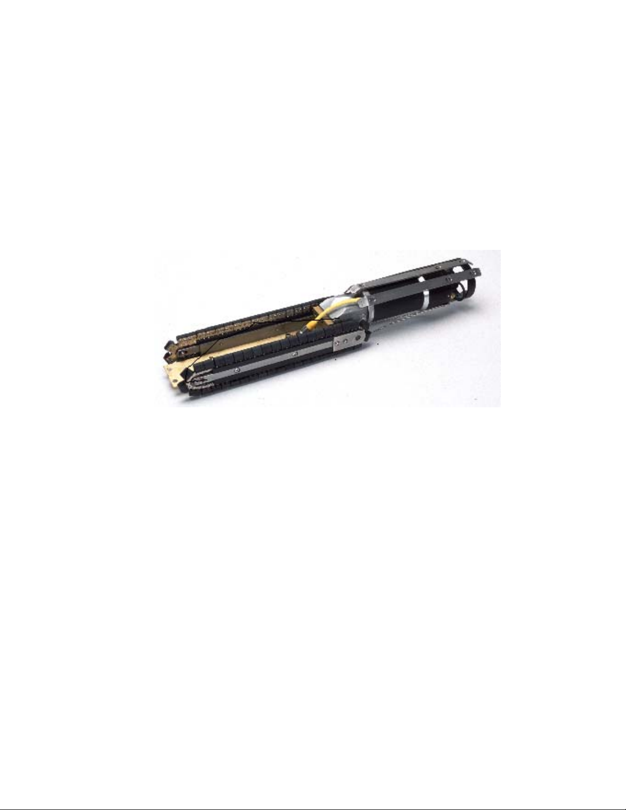
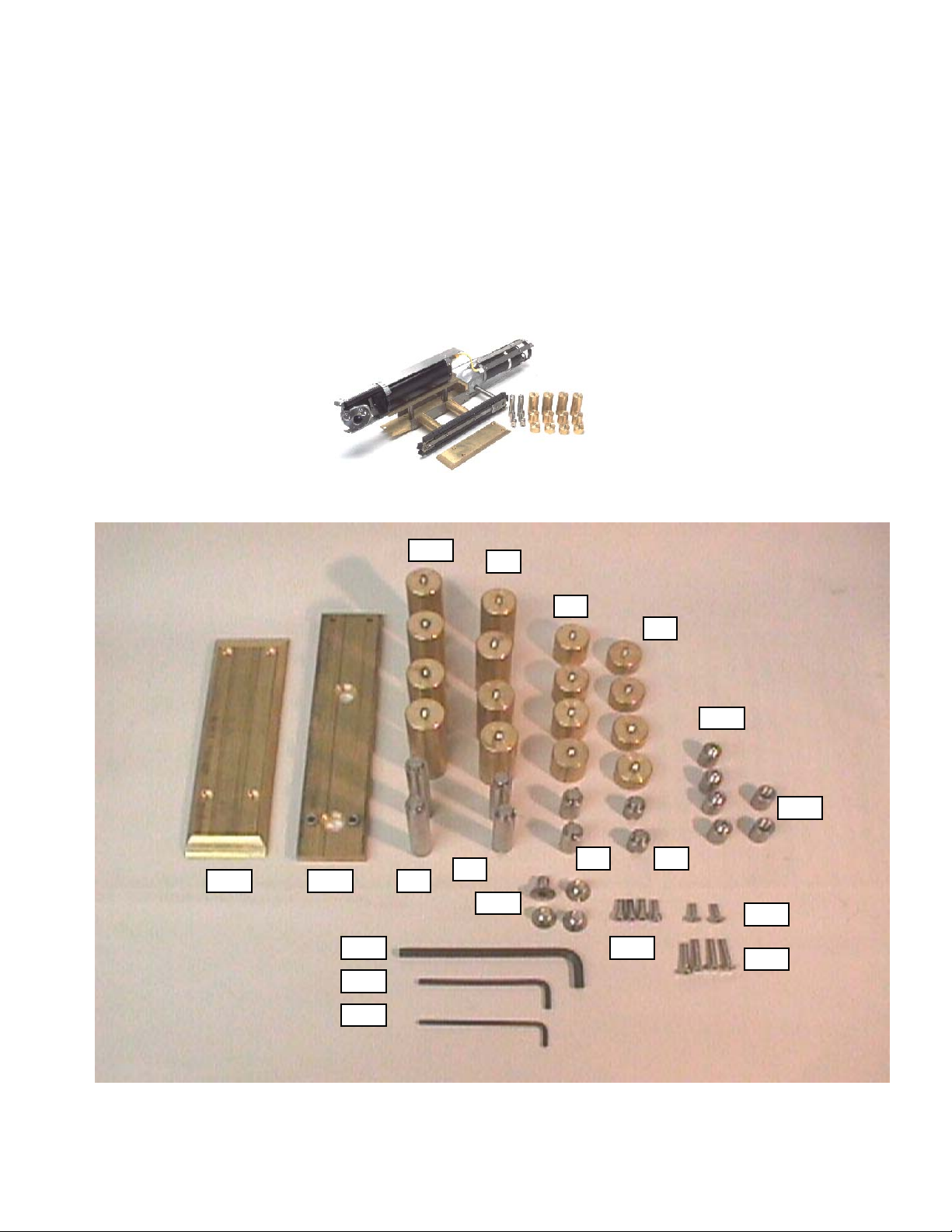
840-30586 KIT, ACCESSORIES, 6” CRAWLER
1701-30994 BOX, TOOL, PLASTIC, W/TRAY 1.0 EA.
2 706-30754 LABEL, KIT, ACCESSORIES, 6" CRAWLER 1.0 EA.
3867-30920 ASSY, COUPLING, EXTENSION, .87", CRAWLER 2.0 EA.
4867-30921 ASSY, COUPLING, EXTENSION, 1.50", CRAWLER 2.0 EA.
5867-31713 ASSY, COUPLING, EXTENSION, 2.37", CRAWLER 2.0 EA.
6867-30922 ASSY, COUPLING, EXTENSION, 3.18", CRAWLER 2.0 EA.
7867-30925 ASSY, SPACER, 87" LONG, EXTENSION SET, CRAWLER 4.0 EA.
8867-30926 ASSY, SPACER, 1.50" LONG, EXTENSION SET, CRAWLER 4.0 EA.
9867-30927 ASSY, SPACER, 3.18" LONG, EXTENSION SET, CRAWLER 4.0 EA.
20 800-17114 ASSY, SPACER, 1.0", M/L TRACTOR TREAD 4.0 EA.
21 402-17109 SPACER, MTG., 1.0"EXTENSION, ML TRACTOR TREAD 2.0 EA.
22 453-30916-23 PLATE, BALLAST, BOTTOM, 6" CRAWLER PLATED 1.0 EA.
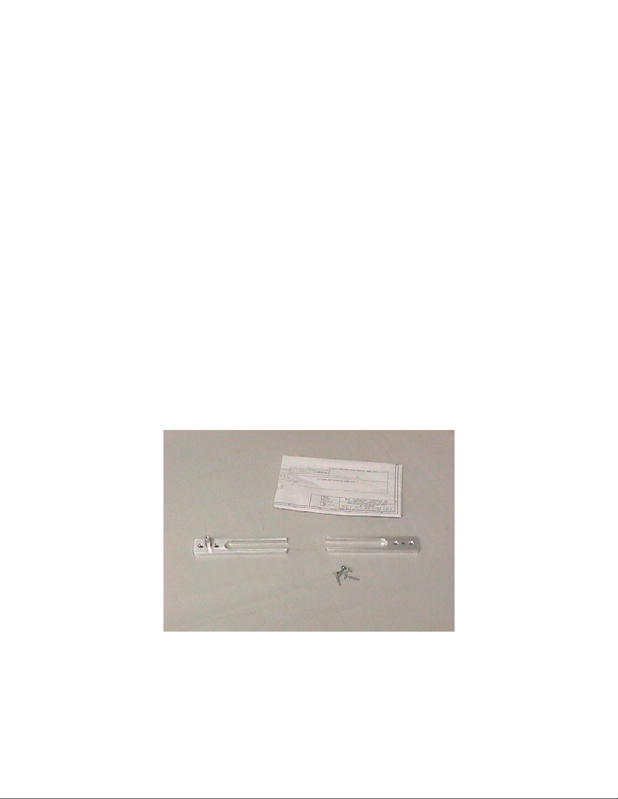
23 867-3093 ASSY, PLATE, MTG., OE3 CAMERA, CRAWLER 1.0 EA.
24 301-12650 MSCR, FLT, HXS, 1/2-13X.75 SS 4.0 EA.
25 301-11005 MSCR, SHCS, 1/4-20X.62 SS 4.0 EA.
26 301-11360 MSCR, FLT, HXS, 1/4-20X1.25 SS 4.0 EA.
27 301-11183 MSCR, FLT, HXS, 1/4-20X.75 SS 2.0 EA.
28 634-10642 WRENCH, ALLEN, 3/16, LONG ARM 1.0 EA.
29 634-11114 WRENCH, ALLEN, 5/32, LONG ARM 1.0 EA.
30 634-17242 WRENCH, ALLEN, 5/16, LONG ARM 1.0 EA.
Options
Truck mount kit; part #840-21751.

Document Number 900-21806 Rev C 9
Operation System Power
CAUTION: NEVER HOOK UP OR DISCONNECT ANY EQUIPMENT
WITH POWER TURNED ON!
The Inspection System requires a steady supply of 120VAC to operate properly.
Before starting of the generator or connecting shore power, make sure that ALL
equipment inside the vehicle has been turned OFF. Turn down the controls for
camera power and cable reel speed. After all equipment has been checked,
connect the shore power cord.
If a generator is to be used, allow the generator to warm up for a few
minutes.
Note: Diesel generators use a different control panel that is separate from the
controller power supply. Refer to the appropriate generator operators manual for
starting.
Verify that the voltage and frequency indicators on the controller power supply
are in the green normal zone.
Caution: Before turning on any equipment, plug the keyboard into the data
collection system. Plug the Auxiliary Control Box into the Auxiliary Control
jack on the controller power supply.
Caution: If the voltage or frequency fluctuates into the red zones on the
controller power supply, DO NOT turn on any of the equipment in the truck.
Check shore power or the generator for proper operation, or have them
checked by a qualified technician.
Caution: Route cords away from traffic or wet areas to avoid tripping on
power cords.

Document Number 900-21806 Rev C 10
Placement of Inspection Truck
Locate the back of the truck so that the cable reel lines up in the direction of the
pipeline to be inspected.
Allow room to work around the opening while carrying the equipment.
Pull camera/tractor far enough into pipeline to clear the bridle or cable grip.
Check all camera and tractor functions again before proceeding.
Move tractor forward so the rear of the tractor and the cable connections are fully
inside the pipe.
Set up down hole poles, shoes and manhole roller.
Reset the footage counter.
Release the drag brake on the cable reel.
Set cable reel in the free wheel.
Keep enough room to work around the opening while carrying the equipment.
Placing the equipment into the line
Follow cable grip, bridle and pig tail instructions.
Re-check the pipeline size and extension adjustments.
Do not let cable “loop” at the location where it enters pipeline.
Use guide poles with hook to keep the crawler stable as it enters pipeline.
Caution: Maintain control of equipment while loading and unloading
into manhole.
Most equipment damage occurs when camera is lowered into hole.
Pull camera/crawler far enough into pipeline to clear the bridle or cable grip.
Set the cable guide.
Use double roller and/or single rollers, for protecting the cable and allowing it to
slide down the hole without drag on the line.
Use enough poles to clear top of the manhole by 2 feet
Caution: Watch out for people, power lines and traffic when handling
the downhole pole

Document Number 900-21806 Rev C 11
0
MAX.
0
1
2
3
LOAD
VOLTS
LINE
AMPS
LOAD AMPS
SPEED
LOW
HIGH
OUT
IN
ON
RESETIRISFOCUS
ON
START
AUX.
INPUT
OFF
NEUTRAL
MIN.
CAMERA REEL
POWER
OFF
STOP
HIGH
LOW
NORMAL
VIDEO LEVELA.C. VOLTAGEFREQUENCY
R.S. TECHNICAL SERVICES INC.
Crawler Operation
Ensure that the Camera ON/OFF switch is in the OFF position before connecting camera
to tractor unit, or auxiliary control box to the Controller Power Supply.
Set the LIGHT INTENSITY control to “MINIMUM”, or full counter clockwise position.
Set the REEL SPEED control to the ‘MINIMUM”, or full counter clockwise.
When power is applied to the controller power supply, the Frequency and Voltage
indicators will be in the normal range.
Controller Power Supply
Camera control on the Controller Power Supply
The adjustable camera power supply provides a nominal 120V DC to the camera,
transporter, and other down-hole inspection equipment. This section has video processing
circuitry which extracts the video transmitted by the under ground camera into a NTSC
video format. Also incorporated in to the controller is an audio microphone preamplifier,
which provides audio for a VCR.
The Camera ON/OFF switch controls the camera power supply. Above the switch is a
green LED to indicate that the camera power supply is on.
The Camera POWER control knob adjusts the output Voltage of the power supply. This
control adjusts the light intensity of the remote camera. This also can adjust adjusts speed
of the transporter unit.
To engage Crawler in forward gear, turn on Controller Power Supply, and press
“Tractor/ Low Speed” on Auxiliary Control Box.
To change speed of Crawler, press “Tractor/ Med.” or “Tractor / High Speed” on
Auxiliary control box. Always start the Crawler in the “Tractor / Low Speed”.

Document Number 900-21806 Rev C 12
Increase power control knob until a red bar appears on the screen. Decrease power
knob until red bar just leaves the screen. Camera and transporter power does not
increase after red bar limit appears on the screen.
Caution: Do not operate equipment with the over limit red bar on screen.
Increase camera power until the red bar appears on monitor screen and reverse
power until red bar just leaves the screen.
Reduce power before coming to a stop.
To stop Crawler, press “Stop” button on Auxiliary control box.
To engage Crawler in reverse, press “Free Wheel” on Auxiliary control box. The
Crawler has one reverse speed.
Do not back over the Sincon Cable.
The Crawler has an automatic “disengage” feature that allows for the freewheeling
retrieval. To disengage the Crawler, momentarily reverse the direction of Crawler. This
will disengage the drive mechanism and allow the Crawler to be pulled out of the
pipeline in “freewheel” by the cable reel.
Pull the Sincon Cable and Crawler back using cable reel with Crawler in free wheel.
To “free wheel” Crawler when traveling forward, press “Stop” on Auxiliary control box.
Note: The Crawler must go into reverse, and then be stopped, to enable Crawler
to free wheel.
Press “Free Wheel” on Auxiliary control box.
When the Crawler starts to move in reverse, press “Stop” on Auxiliary control box.
If Crawler is traveling in reverse and you want the Crawler to “free wheel”, press
“Stop” on Auxiliary control box.
OVER-
VOLTAGE
INDICATOR
BAR
SHOWN ON A
MONITOR
SCREEN

Document Number 900-21806 Rev C 13
Iris
High
LED
green
Shut ter
Low Free Whl.
Freeze
reverse
CCW
Gai n BK Light
CW
freewheel
hold 3 sec.
Stop Home
RESET
lights
Zoom
STD.
Iris Cl.
Wi de Tele
Iris Op.
Down
Lft. Turn
elev down
Rt. Turn
elev up
UP Foc. I n Foc. Out
Dual Function Control Box
Displ ay
Pan RTPan Left
Wht. Bal.
Auto Foc.
Medium
Auxiliary Control Box
Button function: Crawler Controls
High (tractor) high speed in tractor mode
Medium (tractor) medium speed in tractor mode
Low (tractor) low speed in tractor mode
Free Whl./
reverse (tractor) free wheel tractor/ reverse tractor
Stop (tractor) all stop (tractor)/ hold three seconds for freewheel

Document Number 900-21806 Rev C 14
Pipeline Inspection Run
Start the VCR.
Record condition of manhole.
Recording inside pipeline may have to be started before the footage is set.
Run Crawler / camera through pipeline slowly enough to spot defects.
Do not force Crawler /camera past any large amount of debris.
Beware of large root masses.
Use extra caution around severe offset joints or protruding laterals.
Take notes when passing obstacles or severe offset joints, protruding laterals. The
Crawler will be passing these on the way back.
INSPECTION WITH CRAWLER
The Crawler has three forward speeds: Low, Medium, and High.
Reverse and “Free Wheel “position are for Crawler retrieval.
TV
TRUCK

Document Number 900-21806 Rev C 15
Maintenance
Each time the crawler is removed from the pipeline the entire assembly should
be washed cleaned.
A light spray of chain oil should be used on each track assembly.
Inspect individual crawler feet for damage. Replace if necessary.
Inspect the power cable, bridle, and connector to make sure they have not
been damaged.
Inspect the camera clamps, skids, and mounting hardware.
Inspect bridle, skids, rails, and pigtail connections.
.

Document Number 900-21806 Rev C 16

Document Number 900-21806 Rev C 17
Design and Manufacture of Video Pipeline Inspection Systems
A Full Service Company
SALES SERVICE PARTS
LIMITED WARRANTY POLICY
R.S. Technical Services, Inc. (RST) warrants all items of our manufacture for defects in
materials and / or workmanship for one (1) year from date of receipt by the Customer.
(unless otherwise stated)
This policy is limited to items manufactured by RST. i.e. Camera, Reels, Controllers, Data
Displays, Winches and Tractor Transport Vehicles.
In the event of any malfunction of failure of the equipment, the customer is required to
request authorization from RST to return defective parts or components by calling the RST
toll-free number- 1-800-767-1974 and requesting a MRA number. (see Figs. 1 & 1A for
an example of the form.)
The returned parts or components shall include a packing list, part identity, and the reason
for the return of the part.
Freight costs are the responsibility of the Customer unless otherwise agreed to by RST.
All in warranty equipment in need of repair shall be shipped to:
R.S.Technical Services, Inc. or R.S.Technical Service, Inc
1327 Clegg St. 292 Midland Trail
Petaluma, CA 94954 Mt. Sterling, KY 40353
RST shall at our option, repair or replace any defective part or component in our service
facility, or ship the customer a replacement component or part.
The customer shall return the defective part or component within ten (10) working days
after receipt of the replacement for credit.
Not covered by this policy are expendable or wear-out items i.e. light bulbs, drive belts,
cable connectors.
The generator, monitors, VCRs and air conditioner shall be covered by the Manufacturer’s
warranty and any services shall be referred to each Manufacturer’s service organization.
No warranty shall be applicable to malfunctions due to damage, neglect, wear, misuse, or
improper handling or repairs to any part of the equipment.
Improper repairs are deemed to be repairs made by persons other than factory authorized
personnel or repairs not made in accordance with and covered by the manufacturer’s
service manuals, or repairs utilizing parts or materials not equal to those furnished by the
manufacturer.
NOTE: Any un-authorized repairs of any RST equipment will invalidate the warranty.
The responsibility of R.S.Technical Services is set forth above.
RST shall not be liable for any consequential or incidental damages to persons or
property resulting from use of or any breach of warranty expressed or implied, to
this (these) products.

Document Number 900-21806 Rev C 18
MERCHANDISE RETURN AUTHORIZATION (MRA) POLICY
Instructions
Returns will not be processed without Customer Information.
Note: There will be a charge of $25.00 to research incomplete information.
MRA # - Enter the number assigned to this return by RST.
Customer Return Address – If this item is to be returned to you, enter your shipping address.
Bill To – Complete if your billing address is different than your shipping address or if you have a
distributor.
Return Authorized By – Enter the name of the RST employee approving this return. Always call
before returning any item. Items received without a MRA # will be delayed in handling and
subject to a $25.00 research fee.
P.O. Required – If you issue P.O. Numbers, check the required box. If you issue P.O. Numbers
before repair, enter the number here.
Estimate if Over – Enter the maximum you can authorize without being contacted by RST for
approval. This will add time to your repair.
Estimate Before Repair – Check the appropriate box.
Repair, Replacement, Loaner, Credit – Check the appropriate box. Include invoice number if
return is for credit.
Credit Invoice – You must include an invoice number to receive a credit.
Other – Note in space why item is being returned.
Model – Enter the RST Model # of the unit you are returning. If you do not know the model #, the
authorizing person can help you or use the description line.
Serial Number – A serial number is stamped on most RST units. If you are returning a part, use
the serial number from the unit in which the part is used.
Describe Reason Returning – Give as much information as possible describing your reason for
returning the item.
Should you have any questions please contact Customer Service at 800-801-1199.

Document Number 900-21806 Rev C 19
Design and Manufacture of Video Pipeline Inspection Systems
A Full Service Company
SALES SERVICE PARTS
THE FOLLOWING FORM IS PROVIDED FOR YOUR CONVENIENCE
MAKE COPIES OF THE FORM FOR YOUR USE.
FILL OUT THE FORM COMPLETELY AND OBTAIN AN MRA NUMBER
MAKE A COPY OF THE COMPLETED FORM FOR YOUR RECORDS
INCLUDE THE ORIGINAL WITH THE EQUIPMENT OR PART (S) THAT ARE BEING
RETURNED.

Document Number 900-21806 Rev C 20
R.S. Technical Services, Inc.
1327 Clegg Street Date: ______________________
Petaluma, CA 94954
707-778-1974 MRA #
Customer Return Address: Bill To / Distributor:
________________________________________________________________________________________________
________________________________________________________________________________________________
________________________________________________________________________________________________
________________________________________________________________________________________________
Contact: ___________________________ Phone: ________________________ Fax: _________________________
Return Authorized by: _________________________________________________
P.O. Required # __________________________ Replacement
Estimate Required if over ____________________ Credit Invoice # ___________________
Estimate Required Before Repair Other: ____________________________
Repair ___________________________________
Model Number____________________Description______________________________________________________
Serial Number: ___________________________________
Briefly Describe Reason for Return: _________________________________________________________________
________________________________________________________________________________________________
________________________________________________________________________________________________
________________________________________________________________________________________________
________________________________________________________________________________________________
RST Use Only: ___________________________________________________________________________________
________________________________________________________________________________________________
________________________________________________________________________________________________
Table of contents
Other RS Industrial Equipment manuals
Popular Industrial Equipment manuals by other brands

Modine Manufacturing
Modine Manufacturing ElectroFin quick start guide

Bondtech
Bondtech LGX lite V2 on the Creality Ender-7 quick start guide

STIEBEL ELTRON
STIEBEL ELTRON HSBC 225 S Operation and installation manual

Tidland
Tidland 900 KA Series Operation & maintenance manual

Allen-Bradley
Allen-Bradley 140G-R-TLC63 Installation

Dynabrade
Dynabrade Dynafire III 15420 operating instructions