Eastey Value VS1620TK User manual

VS1620TK
Hot-Knife L-Sealer & Tunnel Combo
Value Series
User Guide


VS1620TK
Hot-Knife L-Sealer & Heat Tunnel Combo
Value Series
User Guide
Revised 02/25/2022
P/N VS000004 Rev B
Copyright and Trademarks
Copyright ©2013-2022 Engage Technologies Corporation.
All rights reserved. All trademarks and brand names
are the property of their respective owners.
Eastey
7041 Boone Ave. N.
Brooklyn Park, MN 55428
Phone: (763) 428-4846; Fax (763) 795-8867; 1-800-835-9344
www.eastey.com


Contents
Safety ............................................................................................................................. 7
Explanation of Symbols................................................................................................. 8
Introduction ................................................................................................................... 9
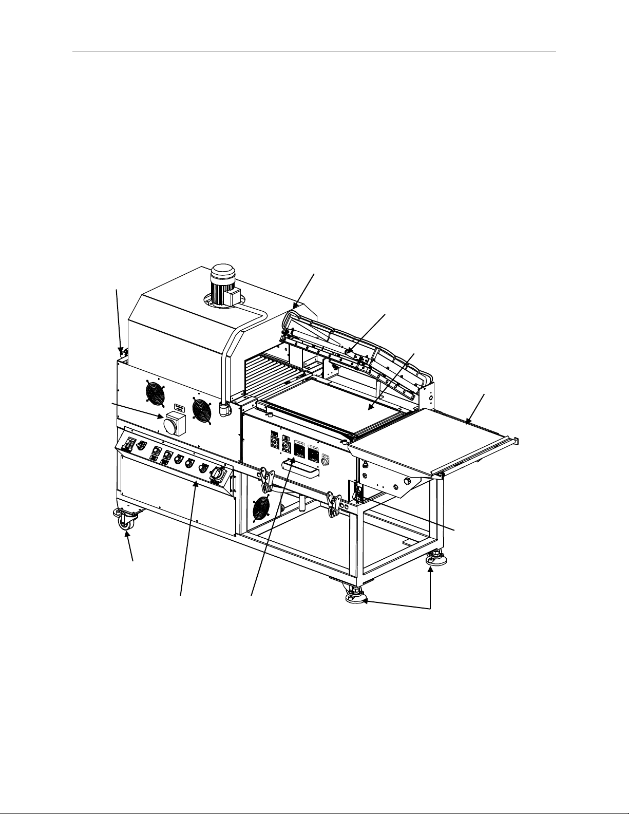
VS1620TK Hot-Knife L-Sealer and Heat Tunnel Combo .............................................. 9
System Overview .......................................................................................................... 9
Specifications.............................................................................................................. 10
Dimensions ............................................................................................................. 11
Installation and Set Up................................................................................................ 12
Unpacking ................................................................................................................... 12
Assembly .................................................................................................................... 12
Product Tray ........................................................................................................... 12
Power Cord............................................................................................................. 13
Location Requirements ............................................................................................... 13
Aligning the Seal Head Limit Switch and Actuator ...................................................... 14
Loading the Film.......................................................................................................... 14
Threading the Shrink Film ........................................................................................... 16
Aligning the Heat-Shrink Tunnel.................................................................................. 17
Seal Head Height Adjustment ..................................................................................... 18
Operation ..................................................................................................................... 19
Sealer and Tunnel Operation ...................................................................................... 19
Main Power............................................................................................................. 20
Conveyor and Blower.............................................................................................. 20
Tunnel Heater ......................................................................................................... 20
Setting the Tunnel Temperature ............................................................................. 21
Blower Speed ......................................................................................................... 21
Conveyor Speed ..................................................................................................... 21
E-Stop or Emergency Stop ..................................................................................... 22
Sealer Operation......................................................................................................... 22
Seal Power Off / On................................................................................................ 22
M.D. Thermo. — Machine Direction or Front Seal Temperature Control ................ 22
T.D. Thermo — Transverse Direction or Side Seal Temperature Control................ 23
Seal Time................................................................................................................ 23
Take Away Time ..................................................................................................... 23
Sealing the Product ................................................................................................ 24
Shutting Down............................................................................................................. 24
Special Notes About the Tunnel Shutdown Sequence ........................................... 25
Maintenance ................................................................................................................ 26
Sealer.......................................................................................................................... 26
Daily........................................................................................................................ 26
Shrink Tunnel.............................................................................................................. 26
Daily........................................................................................................................ 26
Monthly ................................................................................................................... 26
Cleaning...................................................................................................................... 27
Silicone Rubber Seal Pad Replacement ..................................................................... 27
Changing Hot-Knife Inserts and Cutting Rules............................................................ 27

Rollers......................................................................................................................... 28
Troubleshooting .......................................................................................................... 29
Parts List...................................................................................................................... 31
VS1620TK Spare Parts List ........................................................................................ 31
VS1620TK L-Sealer Tunnel Combo Unit .................................................................... 32
Main Assembly – VS1620-TKLR . Live Roller (LTS504(ENG)X2-ALL) VS1620-TKMB
Mesh Belt................................................................................................................ 32
Base Frame with Takeaway Height Adjustment – VSSA0264 (LTS504(ENG)X2-A)
................................................................................................................................ 33
Takeaway Conveyor Assembly – VSSA0265 (LTS504(ENG)X2-B) ....................... 35
Heat Tunnel Assembly with Live Roller Conveyor – VSTA0069LR
(LTS504(ENG)X2-D)............................................................................................... 37
Heat Tunnel Hood & Heaters – VSTA0070 (LTS504(ENG)X2-D-1) ....................... 38
Heat Tunnel Support & Conveyor with Live Rollers – VSTA0071LR
(LTS504(ENG)X2-D-2) ........................................................................................... 40
Heat Tunnel Assembly with Wire Mesh Belt Conveyor – VSTA0069MB
(LTS504(ENG)X2-D)............................................................................................... 43
Heat Tunnel Hood & Heaters – VSTA0070 (LTS504(ENG)X2-D-1) ....................... 44
Heat Tunnel Support & Conveyor with Wire Mesh Belt– VSTA0071MB
(LTS504(ENG)X2-D-2) ........................................................................................... 46
L-Sealer and Support with L-Seal Controls – VSSA00266 (LTS504(ENG)X2-E) ... 49
L-Sealer Upper Frame – VSSA0314 (LTS504(ENG)X2-E1)................................... 50
L-Sealer Mid Frame with L-Sealer Controls – VSSA0314 (LTS504(ENG)X2-E-2) . 52
Product Tray with Film Holder and Perforator – VSSA0267 (LTS504(ENG)X2-G) . 55
Main Electrical Panel and Tunnel Control Panel – VSCP0038 (LTS504(ENG)X2-H)
................................................................................................................................ 57
Electrical ..................................................................................................................... 59
Electrical Panel ....................................................................................................... 59
Electrical Parts List ................................................................................................. 60
Appendix A .................................................................................................................. 61
Electrical Schematic (Sheet 1 of 3)......................................................................... 61
Electrical Schematic (Sheet 2 of 3)......................................................................... 62
Electrical Schematic (Sheet 3 of 3)......................................................................... 63
Warranty Statement .................................................................................................... 64
Customer Support....................................................................................................... 65

Safety 7
Safety
Always disconnect electrical power before attempting maintenance to any electrical or
moving parts. Do not tamper with electrical wiring.
Keep hands away from moving conveyors and assemblies.
Never operate this or any moving equipment without all covers and guards in place.
Do not increase the factory settings on either the mechanical or electrical overload
devices.
Do not make any modifications to either the electrical circuitry or the mechanical
assemblies of this machinery.
Heat sealing equipment can become very hot after a period of use. Keep hands away
from hot surfaces if the machine is in operation or has been running recently.
Adequate ventilation should be provided at all times. The use of certain types of plastic
film in sealing or shrinking equipment may result in the release of hazardous fumes due
to the result of degradation of the film at high temperatures. Before using any plastic film
in this equipment, the manufacturer or supplier of the film should be contacted for
specific information concerning the potential release of hazardous fumes.

8Safety
Explanation of Symbols
Caution sign or Safety Alert symbol. Indicates caution, be alert, Your safety
is involved. Knowledge of safe operation is required.
Ground symbol. Indicates ground. Use Class-3 (lower than 1000hms) cable
to ground to earth. Incomplete grounding may lead to electrical shock.
Electrical hazard. Indicates electrical danger. Only a trained electrician can
uncover the electrical panel or box.
Pinch hazard. Do not put your hands or any object on the moving
mechanism. Shut down the machine before doing any maintenance, repair,
or adjustment.
Crush hazard. Do not put your hands or any object on the moving
mechanism. Shut down the machine before performing maintenance, repair,
or adjustment.
High temperature hazard. Do not touch or place hands close to the heating
source to avoid burns. Proceed with any maintenance only when the
temperature of the heater or other heat source has cooled down to room
temperature.
Moisture hazard. Keep equipment dry. This equipment is designed for
indoor operation in a typical clean, dry factory environment, protected from
rain and moisture. Do not operate the machine in any extremely wet or oily
environment that may exceed operating specifications.

Introduction 9
Introduction
VS1620TK Hot-Knife L-Sealer and Heat Tunnel Combo
The Eastey VS1620TK Hot-Knife L-Sealer and Heat Tunnel Combo will seal and shrink
wrap a variety of products all on one frame. It is designed to be very easy to set up and
operate.
System Overview
Exit
Rollers
Hot-Knife
Seal Head
Frame
Take Away
Conveyor
Product
Tray
Leveling
Pads
Casters
Heat Tunnel
Control Panel
Sealer Table
Red Locking
Lever
L-Sealer
Control Panel
Heat Tunnel
E-Stop

10 Introduction
Specifications
Specification Details
Film Material Polyolefin, or PVC Shrink Film
8 in. (20cm) – 18 in. (45cm) width
Power Requirements 220VAC 50/60Hz 30 Amps Single Phase
Machine Weight 650 lbs. (295kg)
Shipping Weight 750 lbs. (340kg)
Sealer Height
Adjustment
Wheel
Film
Roller
Magnet Hold
Down
Pinwheel
Roller

Introduction 11
Dimensions
Dimensions are shown in inches (and centimeters).
Specification Details
Machine Dimensions Length (A) = 86.5 in (218cm)
Width (B) = 32 in. (81cm)
Height (C) = 53.25 in (134cm)
Tunnel Chamber Dimensions Length = 26 in (66cm)
Width = 16 in. (41cm)
Height = 7 in (18cm)
Conveyor Dimensions Length = 24 in. (61cm)
Width = 13.5 in. (34cm)
Height
53.5 in.
(136cm)
(C)
Length
86.5 in.
(218cm)
(A)
Side View End View
Width
32 in.
(81cm)
(B)
M.D.THER MO. T.D. THERMO.
OFF
SEALER
ON
TAKEAWAY
TIME
SEAL
TIME

12 Installation and Set Up
Installation and Set Up
Unpacking
Carefully unpack the Eastey Hot-Knife L-Sealer and Heat Tunnel Combo unit from the
shipping carton.
Remove the shipping bolts and straps that secure the L-Sealer and Heat Tunnel Combo
unit to the shipping pallet. Remove the product tray and lift the L-Sealer and Heat
Tunnel Combo unit off the pallet.
Attention! The Eastey L-Sealer and Tunnel Combo is a very heavy
piece of equipment and will require a forklift or several
people to move safely off the shipping pallet.
For shipping purposes, the product tray has been disassembled from the L-Sealer.
Assembly
The Eastey VS1620TK Hot-Knife L-Sealer and Heat Tunnel unit has been assembled at
the factory and requires very little assembly.
Product Tray
The product tray contains both the film roller and the perforating pinwheel. The product
tray has been disassembled from the sealer for shipping. There are four (4) bolts that
are used to mount the product tray. Use the provided hardware to attach the product
tray to the infeed end of the L-sealer.
Hot-Knife
L-Sealer
Section
Product
Tray
Heat Tunnel
Section

Installation and Set Up 13
Power Cord
The Eastey L-Sealer and Heat Tunnel combo can be used in a variety of locations. To
allow the option of hard wiring the power cord into an existing electrical panel, the
combo unit is shipped without a three-pronged plug attached to the power cord. If the
combo unit is going to be used with a typical three-pronged outlet attach a certified and
approved three-pronged plug to the power cord.
Attention!Ensure that any wiring complies with all electrical wiring
codes and specifications that apply to the installation
location.
Location Requirements
There are four casters located on the bottom of the L-sealer and heat tunnel combo unit
to help in moving the machine. When the combo unit is in the operating location adjust
the four leveling pads for correct height.
When installing the combo unit please be aware of the following considerations:
1. The mounting surface is flat and level.
2. Alignment with any existing packaging lines or conveyors.
The machine should be placed on a flat, level floor so that it does not rock or move. We
recommend that the machine be securely locked in place when used.
When the Eastey L-Sealer and Heat Tunnel Combo unit is positioned in the operating
location, you will need access to:
1. Both control panels: control panel for the sealer and control panel for the tunnel.
2. Seal head handle.
3. Sealer table height adjustment wheel.
4. Sealer table horizontal red locking lever.
5. Shrink film roller.
6. Pin perforation wheels.
These locations are generally accessible from the operator side of the machine. The
film and pinwheel rollers are located under the product tray.

14 Installation and Set Up
Aligning the Seal Head Limit Switch and Actuator
The seal head limit switch and limit switch actuator are located on the hinge upright
angle closest to the heat tunnel.
Attention!Ensure the limit switch and cap screw that activates it are
aligned and the cap screw adjusted so that the head will
activate the limit switch when the front seal bar is
approximately one-eighth to one-quarter inch from the seal
surface.
Loading the Film
Load the new roll of shrink film onto the film roller under the product tray. Install the film
roll so the center fold is at the back of the machine (the operator side is considered the
“Front” of the machine).
To load a roll of film:
•Lift the shrink film roller off the roller mounts located beneath the product tray.
•Loosen the locking knob on one of the film cores and slide it off the roller.
•Install the new roll of shrink film onto the film roller.
•Reinstall the film core.
•The film position is adjustable. Loosen the film core retaining collar lock knobs and
position the shrink film roll according to the product size. Retighten the retaining
collar locking knobs.
Cap
Screw
Limit
Switch
View

Installation and Set Up 15
The pin perforation wheel punches small holes in the shrink wrap to allow air to
evacuate while in the shrink tunnel. Loosen the pin perforation adjustment knobs at
each end of the perforating wheel roller and move the perforation rollers away from the
rubber roller. Position the pin perforation rollers according to the product size. After
threading the film move the perforating wheels back to the operating position (against
the rubber roller) and retighten the pin perforation adjustment knobs.
The product tray position is adjustable. Loosen the product tray adjustment knob and
align the product tray with the center fold edge of the shrink film. Retighten the
adjustment knob.
Film and Product Alignment Diagram
Film Core
Thumb Screw
Locking Knobs
Pin
Perforation
Adjustment
Knobs
Shrink Film
Roller
Product Tray
Adjustment Knob
Pin
Perforation
Adjustment
Knob
Pinwheel
Perforation
Rollers
Perforation
Pinwheels
Product Tray
Film Core
Retaining Collar
Film Core
Retaining Collar
Operator
Side
End of
Tray

16 Installation and Set Up
Threading the Shrink Film
Thread the shrink film over the perforating wheel and around the end roller. Immediately
after the end roller, separate the shrink film, with the top of the film traveling over the
product tray and the bottom traveling underneath the product tray.
Film Threading Diagram
Product
Tray
Note: Split the
Film Here
End
Roller
Perforating
Wheel
Shrink Film
Roll
Rubber
Roller

Installation and Set Up 17
Aligning the Heat-Shrink Tunnel
When the film, product tray and product are correctly aligned, release the red lever
stopper and position the entire L-sealer and product tray assembly in line with the heat
shrink tunnel opening, centering the product with the center of the tunnel. Reset the red
lever stopper to lock the L-sealer and product tray assembly in position.
Red Lever
Stopper
Shrink
Tunnel
Opening
L-Sealer and
Product Tray
Assembly

18 Installation and Set Up
Seal Head Height Adjustment
To adjust the vertical height of the L-sealer, use the height adjustment wheel located
under the sealing assembly. Turn the wheel to move the L-sealer position up or down.
Position the center of the seal as near as possible to the center of the product to be
sealed.
Seal Head Height
Adjustment Wheel
Seal Line
Take Away
Conveyor
Center the seal on the
side of the product to
be sealed

Operation 19
Operation
The Eastey VS1620TK Hot-Knife L-Sealer and Heat Tunnel Combo is very easy to
operate. Become familiar with the control panels for the heat tunnel and L-sealer
located on the operator side of the machine.
Sealer and Tunnel Operation
M.D. THERMO. T.D . THERMO.
OFF
SEALER
ON
TAKEAWAY
TIME
SEAL
TIME
Emergency Stop
E-STOP
Emergency Stop
E-Stop
Tunnel Controls
L-Sealer Controls
Handwheel for setting center of
seal height

20 Operation
Main Power
To begin operation, turn the Main Switch to the ON
position.
The Main Switch controls power to both the tunnel and
sealer.
Conveyor and Blower
Press the Conveyor and Blower ON (green button) to start the conveyor and
blower in the heat tunnel.
To turn the conveyor and blower off press the red Conveyor and Blower
OFF button.
Tunnel Heater
Turn the tunnel Heater switch to the ON position.
Table of contents
Other Eastey Industrial Equipment manuals

Eastey
Eastey Value VSA2530TK-V1 User manual

Eastey
Eastey Perfomance ETB Series User manual

Eastey
Eastey SB-2 HD User manual

Eastey
Eastey L-Bar Sealer Tunnel Combo Unit Value Series User manual

Eastey
Eastey BB-2 SS User manual

Eastey
Eastey Value VSA2530TK-V1 User manual

Eastey
Eastey EA Professional Series User manual

Eastey
Eastey ERX Series User manual

Eastey
Eastey BB-2 User manual

Eastey
Eastey SB-2EX User manual