OperatingInstructions
ModelsH500,H80O
and H880
vapor. Never operate or repair near a
flammable gasor vapor. Never store
flammable tiquids or Eases
in the
vi.inity of the hoist.
24.Warn
personnel
of anapproaching
load.
Make
sureallpersons
stay
clearof suspendedload.
25.
Keep
hands
clearofcablespool.
26.Donot lift more
thanthe rated
toao.
AWARNING Do not tift toads
over people or
teavea suspended toad unattended.
27.8e
certainloadiscenteredunder
hoist
to avoidanyswinging
of load.
28.Maintainfirm footing when
operatinghoist,
Donotallow
your
attention
to bediverted.
29.
Take
upslack
carefully,checkload
balance,lift afew inchesand
check
Ioadholding
action
before
contrnurng.
30.Keepbrake
surfaceandlining{ree
of grease.
31.Inspectregularly,
andkeep
accurate
maintenance
records.
Permitonly
qualified
personnel
to adjustor
repair
hoi5t.
32.Donot use
damagedor
malfunctioning
hoist
untilall
necessary
adjustments
or repairs
have
been
made.
AWARNING Make aertain
power supply is
disconnected berore attempting to
service, relocate, or perlotm any
rnaintenance-
lf power disconned point
is out-of-sighL tock it in the open
position and tag ta prevent unexpected
applicationof power.
33.Mako
certainloadis
removedfrom
hoistbefore
performing
anyservice.
34.Only
qualified
electrician
orservice
person
should
perform
any
electrical
troubleshooting
or maintenance.
35.UseonlyPowerwinchreplacement
parts
with thishoist.
Installation
AWARNING Hoist is not
suitablelor usein
outdoor tocations or areas containing
explosive dust, vapo's, or gases. Do not
use hoist in or around wet areas, lhe
instaltation area must provide sale
operating <onditions fot the operator,
in.luding sufficient room for the
operator and other pe/'sonnel to stand
ctear of the load at atl times.
1. Attach the hoistto supporting
structure usingthe brackets
and
bolts provided- Failure
to usethe
supplied anchoring hardware will
void the warranty.
2.
5.
Makesure
any
mounting
pointfor
the hoistis
structurally
strong
enoughfor manytimes
the hoist
rated
capacity.
lf supporting
the hoistinroof
trusses,
makesureto distributethe
load
overmorethanoneortwo
trusses
byextending
thesupport.
Makecertain
thehoistis
notfree
to
swingorturn in
the mountings.
Intended
for useon 115V,
single
phase,
60Hz
power
supply.Voltage
atthe hoistshould
bewithin plus
or
minus10%
of 115V.
Equipped
with
3-prong,
grounding-
type
plug
to minimize
shockhazards
Itmust
be
plugged
into
aproperly
installed
and
grounded
receptacle
to
maintain
this
protection.
A heawduty,
three
prong
extension
cordmust
beusedif required
to plug
in
thehoist.
Anertension
cordwhictr
is
toosmallwillrestrict
power
tothe
hoist
andreducelifting
capacity.
Pu5hbutton
station.brake
andlimit
switches
shouldbe
tested
bythe
7.
operatorbeforebeginning
a
job.lf
thesecontrolsdo notoperate
properly,
theyshouldberepaired
or
replaced
beforeoperationsare
started.
LIMIT SWITCH
Beiore
placing
hoistin
operation,che(k
forproper
upperlimit
switchoperation.
Push
UPbutton.
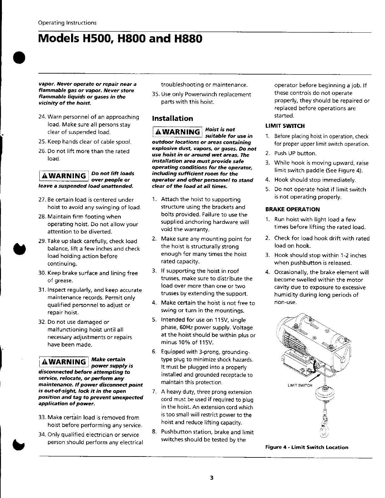
Whilehook ismoving
upward,
raise
limit
switch
paddle(see
Figure4).
4. Hook
shouldstopimmediately.
5. Donot operatehoistif limit
switch
isnotoperating
properly.
BRAKEOPERATION
1. Runhoist
with lightload
afew
times
beforeliftingthe rated
load.
2. Check
for loadhookdrift with rated
load
on hook.
3.
1.
2.
3.
3. Hook
shouldstopwithin l-2 inches
whenpushbutton
isreleased.
Occasionally,
the brakeelementwi
becomeswelled
withinthe motor
cavltydue to exposureto excessive
humidity
duringlongperiods
of
non-u5e.
8.
!
,-&\.
-v:
Figure 4 - Limit Switch Location