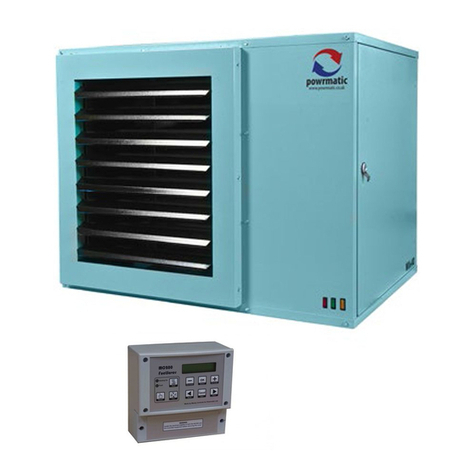
Powrmatic PAG 60 User manual

WARNING: THIS APPLIANCE MUST BE EARTHED
The PAG Range
Users Instructions
£1.00 When supplied separately. PAG Issue 3 December 1997
Every effort is made to ensure accuracy at time of going to press. However as part of our policy of continual product improvement, we reserve the right to alter specifications without prior notice.
CE

1. Checks before lighting the Air Heater
The following preliminary checks should be made before
lighting the heater(s)
a)EnsurethattheELECTRICALsupplytotheheaterisswitched
OFF.
b) Check that all warm air delivery outlets are open.
c) Check that the thermostat is set at MAX.
d) Check that the clock control is set to an ON period.
e) Check that any other controls are calling for heat.
f) Ensure that the Summer/Winter switch is in the Winter
position.
g) Check that the overheat reset button has not operated.
2. Lighting the Air Heater
NOTE:Oninitiallightingoftheheater(s),itmaytakesometime
topurgetheinternalpipeworkofair.Ifitisnotpossibletolight
the heater after several attempts contact the local service
company.
2.1 PAG 60 - 100
NOTES:
- When attempting to light the pilot at any time ensure that the
mains electricity supply is switched off.
1. Remove the middle front panel.
2. Press the knob of the multifunctional
control (Fig.3a - 1) and rotate to Pilot.
3. Light the pilot flame by pressing the piezo unit button,
locatedon theheaterframe attherighthand side,severaltimes,
keeping the multifunctional control knob depressed. The pilot
flame may be viewed through the sight glass on the front of the
unit.
4. Once the pilot has been established continue pressing the
control knob for approximately 30 seconds and then slowly
release. The pilot should remain alight.
WARNING: Should the pilot be extinguished at any time,
either intentionally or unintentionally, slightly depress the
control knob and rotate clockwise to Off.Wait 3 minutes
before attempting to relight the gas, then repeat steps 3-5
above.
6.Slightly depress thecontrolknoband turn
to On.
7. Switch on the electricity supply at the isolator, and the main
burners will light.
8. SHUT OFF
To interrupt all gas flow through the
multifunctional control slightly depress the
control knob and rotate clockwise to Off.
CAUTION
The restart interlock device prevents the heater from
re-igniting until the flame supervision device has interrupted
the gas flow. After waiting 3 minutes the heater may be relit by
following the previous instructions.
2.2 PAG 200
1. Turn on the gas service valve.
2.Switchontheelectricalsupplyattheisolatorand theignition
sequence will commence. After a delay of approximately 30
seconds the ignition spark will be generated and the main gas
valves energized. The burners will then light.
3. If the burners fail to light the control box will go to lockout
and the lockout reset switch at the right hand side of the heater
will be illuminated. To restart the ignition sequence press the
reset switch.
4. SHUT OFF
Switch OFF the electrical supply to the heater or set the clock
control to OFF or set the room thermostat to MIN.
3. To Shut Down the Air Heater
3.1 For Short Periods: Turn the room thermostat to OFF
or the lowest setting.
3.2 For Long Periods: Turn the room thermostat to OFF
orthelowestsetting, slightlydepressthecontrolknoband
rotate clockwise to Off. Wait approximately 4-5 minutes
for the main air fan of the heater to stop running and the
turn off the gas and electric supplies to the heater.
4. Description of Operation
Important:Allheatersmustbecontrolledbythefittedexternal
controls and not by use of the main switch in the electrical
supply to the heater.
4.1 PAG 60 - 100
With the permanent pilot alight the main burners will be
switchedonandoffbythefittedexternalcontrolse.g.Timeclock,
room thermostat etc. Approximately 2 minutes after the main
burnerslight theheaterfanwillbeautomaticallystarted.When
the external controls are satisfied the main burners will be
turned off and approximately 2 - 3 minutes later the heater fan
will be automatically stopped.
4.2 PAG 200
The ignition sequence will commence each time that the
external controls e.g. Timeclock, room thermostat etc. call for
heat. Approximately 2 minutes after the main burners light the
heater fan will be automatically started. When the external
controls are satisfied the main burners will be turned off and
approximately 2 - 3 minutes later the heater fan will be
automatically stopped.
4.3 Summer / Winter Modes
Certain types of external controls will provide for two modes
of operation i.e.
Summer: The heater fan alone will run at the dictate of the
external controls to provide air movement.
Winter: The heater will operate normally.
5. Limit Control
In the event of a fault that causes the temperature of the air
leavingtheairheatertorisesignificantlye.g.Blockedairinlets,
the limit thermostat will operate to shut down the burner.
Remove the cause of the fault, wait 10 minutes and then reset
the thermostat by pushing the green reset button located on the
right hand side of the heater. If the limit thermostat continues
to operate turn off the air heater and call a service engineer.
5. Maintenance
Regularservicingisessential tomaintainefficient,reliableand
safe operation of the heater. Users are strongly recommended
to have the heater serviced by a qualified person at least
annually and preferably at the end of the heating season.
6. IMPORTANT
Free access must be maintained to and around the heater for
servicing purposes and the air supply to the heater must not be

restrictedinanyway.Combustiblematerialsmustnotbestored
adjacent to the heater.
If at any time a gas leak is suspected turn OFF the gas supply
-DO NOT USE A NAKED FLAME- and contact the local gas
undertaking immediately.
Gas Safety (Installation & Use) Regulations 1994
It is law that all gas appliances are installed, adjusted and, if
necessary, converted by qualified persons* in accordance with
the above regulations. Failure to install appliances correctly
can lead to prosecution. It is in your own interests and that of
safety to ensure that the law is complied with.
* e.g. Corgi Registered

HEATING DIVISION
Winterhay Lane
Ilminster, Somerset TA19 9PQ
Tel: 01460 53535 Fax: 01460 52341
Every effort is made to ensure accuracy at time of going to press. However as part of our policy of continual product improvement, we reserve the right to alter specifications without prior notice.
This manual suits for next models
2
Other Powrmatic Range manuals
Popular Range manuals by other brands

Whirlpool
Whirlpool RF3120XP Use & care guide
Whirlpool
Whirlpool WEE750H0H installation instructions

Lotus
Lotus CF4-68ET Installation and operating instructions
GE
GE JDS28DF1WW installation instructions

Maytag
Maytag MGT8720DS00 Use & care guide
GE
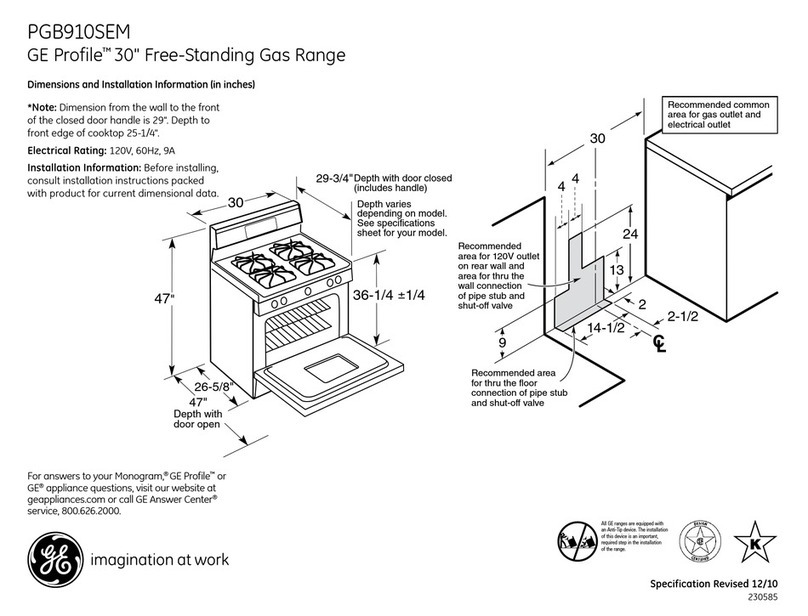
GE Profile PGB910SEMSS Dimensions and installation information
