Powrtran ProTabs User manual

INSTALLATION AND OPERATIONS MANUAL


TameThe Waves 3
Introduction
Thank you for your purchase of the most advanced and user-friendly
electromechanical trim tabs on the market.
The Pro Tabs were developed out of a necessity for a trim tab which
could be deployed at higher speeds without bending or breaking. The
unique angles and bends of our electropolished tabs provide additional
bracing and strength, while directing waterow to reduce drag.
Contained in this manual, you will nd detailed, step-by-step
installation instructions, as well as, an overview of tab operation.
Please read through this manual in its entirety before beginning
installation. It is also highly recommended to keep this manual
accessible at all times.
If you have any questions, please call our Technical Service line at
1-800-466-7697
24253 COUNTY ROAD 7 ST. CLOUD, MN 56301
1-800-466-7697 WWW.POWRTRAN.COM
A DIVISION OF
4
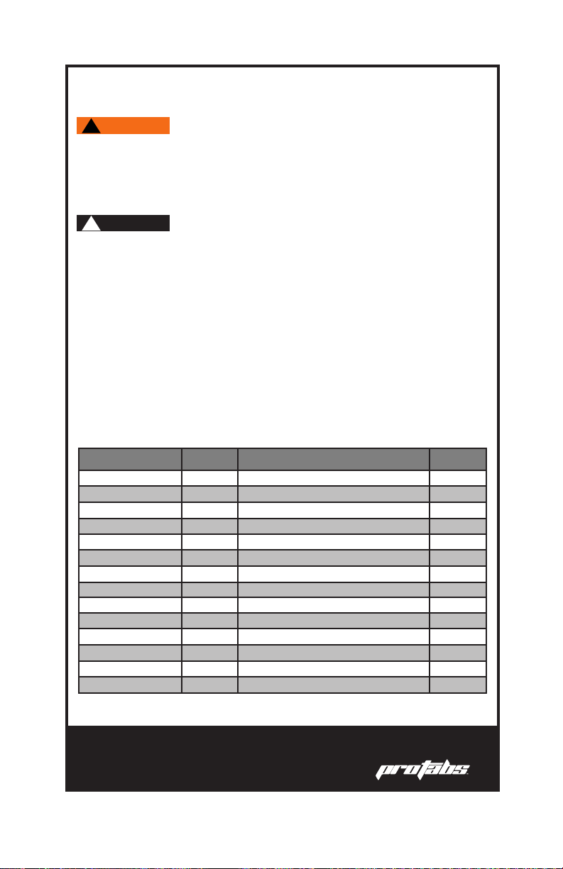
Use of This Manual
This Installation and Operations Manual is an important part of the
product and should be thoroughly read and understood by anyone in
charge of the installation or use of the Pro Tabs.
This manual will use the following symbols to ensure user safety and
guarantee correct installation and operation.
!DANGER
!WARNING
!CAUTION
!NOTICE
Immediate hazards which cause severe injury or death.
A hazard exists which can result in injury or death if
proper precautions are not taken.
A reminder of safety practices or a direction of attention
to unsafe practices which could result in injury.
Important information for the correct installation and
maintenance, that does not cause any damage.
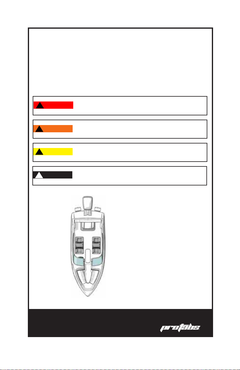
PORTSTARBOARD
STERN
BOW
Nautical terms used in this manual
TameThe Waves 5
Product Description
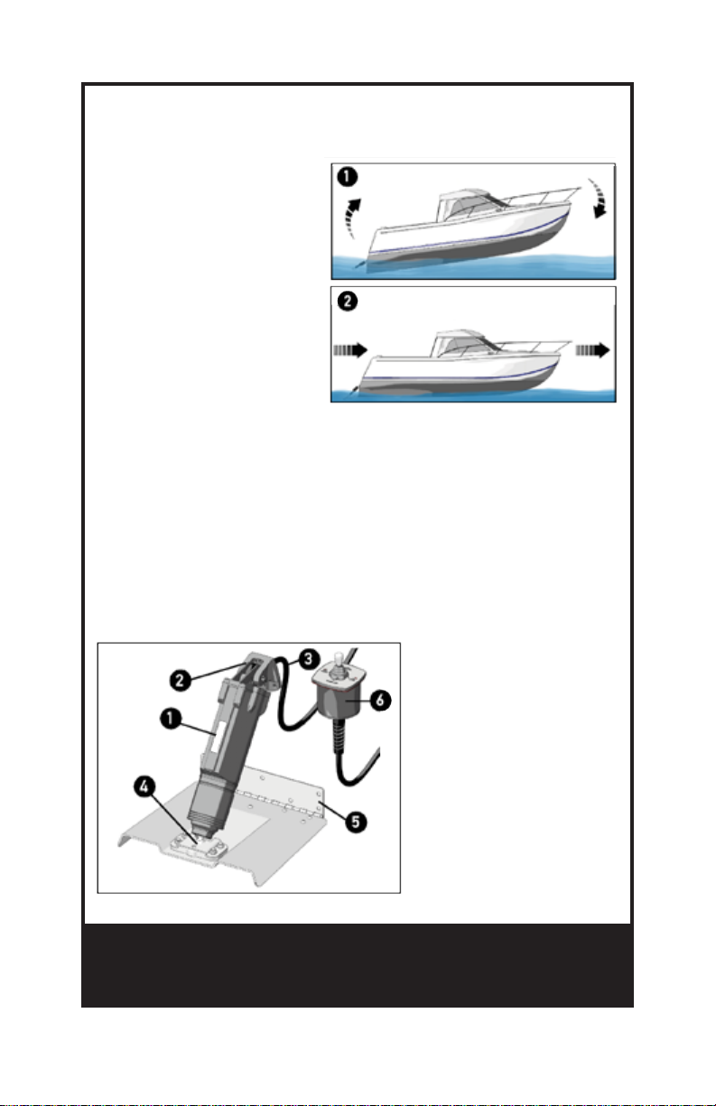
When properly used, the
Pro Tabs allow the boat to
maintain the proper level of
trim according to the dierent
navigation conditions,
optimizing the performance.
Picture 1 denotes a boat’s
porpoising attitude, while
Picture 2 shows the boat’s
proper position achieved
with help from the Pro Tabs.
The working principle behind trim tabs is that the tabs create a lever
with the fulcrum being the on-plane pad of the boat. As the tabs
push down behind the fulcrum, the stern of the boat is raised, thus
lowering the bow.
Peak performance is achieved when the bow and the stern are as level
as possible.
1Actuator
2Connection bracket to
the transom
3Electric cable (6.5’)
4Connection bracket to
the tab
5Tab and hinge
6Joystick
6
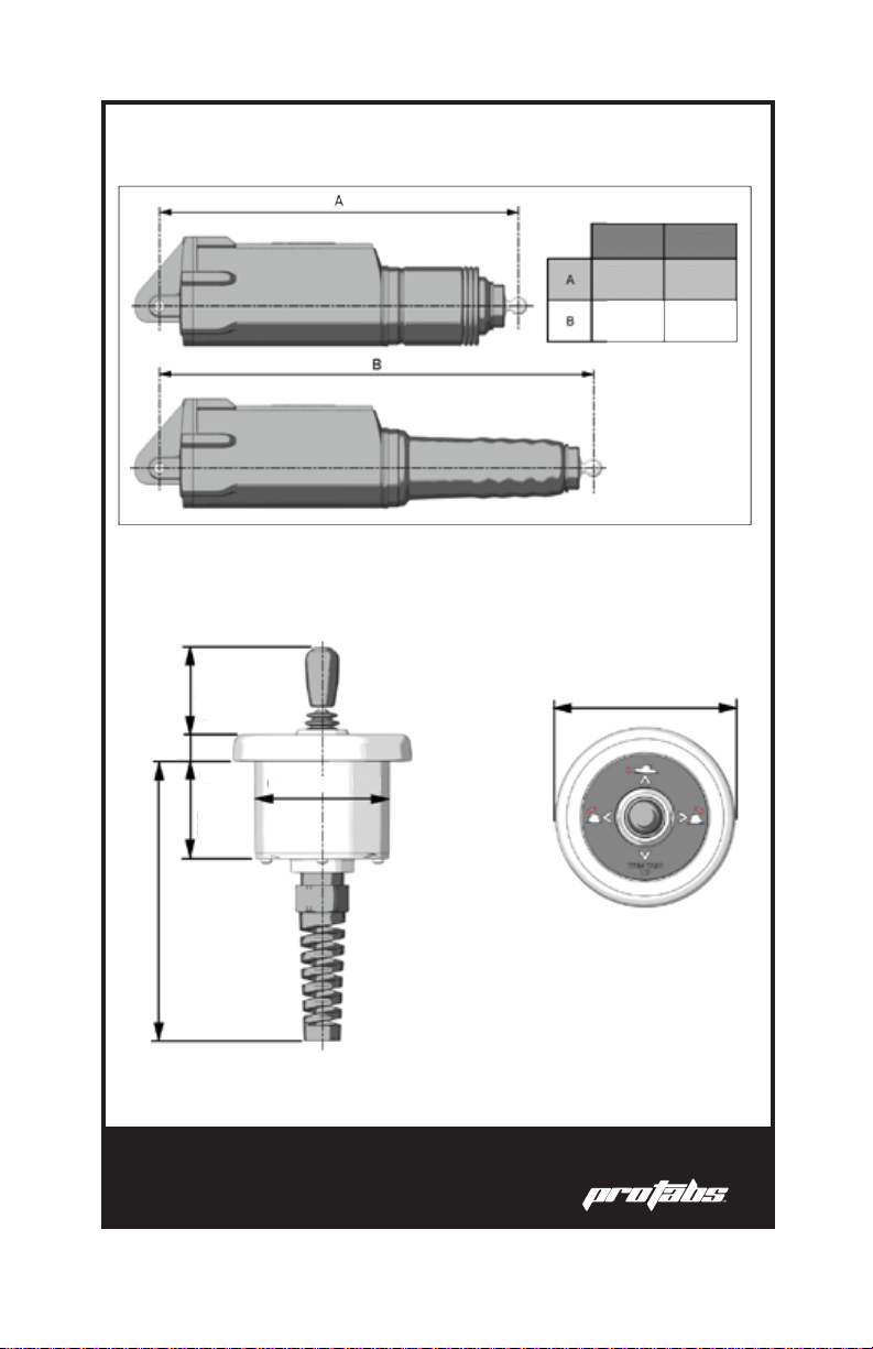
Actuator Dimensions
Joystick Dimensions
COMPACT STANDARD
10.75” 11.75”
14.25”13”
2.75”
3.62”
2”
5.61”
1.82”
0.5”

TameThe Waves 7
TAB Dimensions
Sizing Guidelines
BOAT LENGTH
14’-18’
14’-18’
9” x 9” 12.22”
12.22”
12.22”
12.22”
9” x 9” 10.65” 12”
10.65” 12”
10.65” 12”
10.65” 12”
12” x 9”
12” x 9”
12” x 12”
12” x 12”
12” x 18”
12” x 18”
16’-25’
16’-25’
18’-30’
18’-30’
26’-36’
26’-36’
BOAT LENGTH
TAB SIZE (L X W)
TAB SIZE (L X W)
TRANSOM MIN. HEIGHT
TRANSOM MIN. HEIGHT
TILTED INSTALLATION VERT. INSTALLATION
STANDARD ACTUATOR
COMPACT ACTUATOR
STANDARD DIMENSIONS
A 9” 12” 12” 12”
9” 9” 12” 18”
B
INCHES
1.1”
8
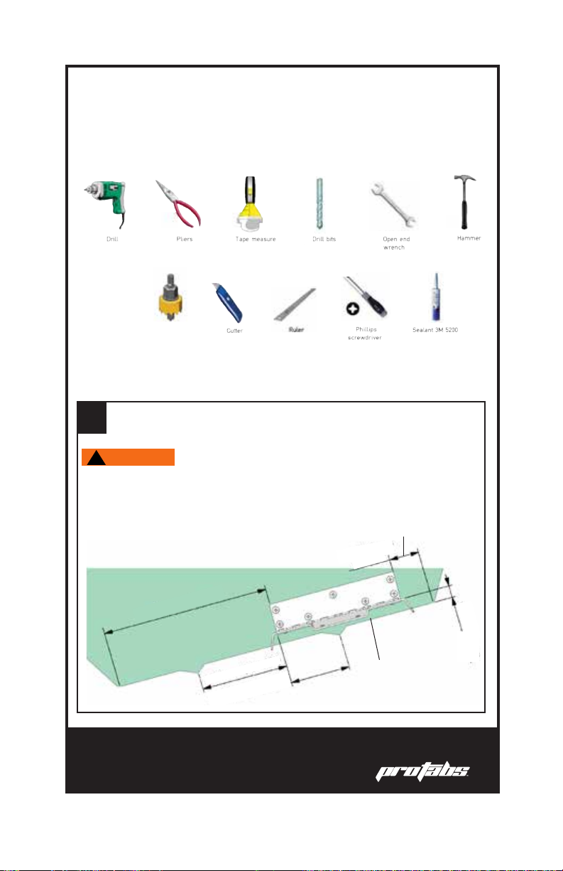
Installation Overview
Installation Steps
1Find the tab installation point as shown in the picture.
Tools Required
7/32”
25/64”
10mm
Hole Saw
2.75”
Please read all instructions carefully BEFORE beginning installation.
Improper installation can lead to failures which can cause injury.
!WARNING
Make sure the Upper Fixing Bracket of the actuator is not near
other devices on the inner part of the transom which may obstruct
the passing of the power cable.
Ensure hinge is paralell to
the bottom of the hull.
The inside edge of the tab must be at least
8” from the centerline of the transom.
The side corner of the hinge must be a
minimum of 2” from the fairing.
2”
2”
The outside edge of the tab
must be at least 1-4” from the
edge of the keel.
1-4”
>
_
>
_
>
_
8”
3/8”
TameThe Waves 9
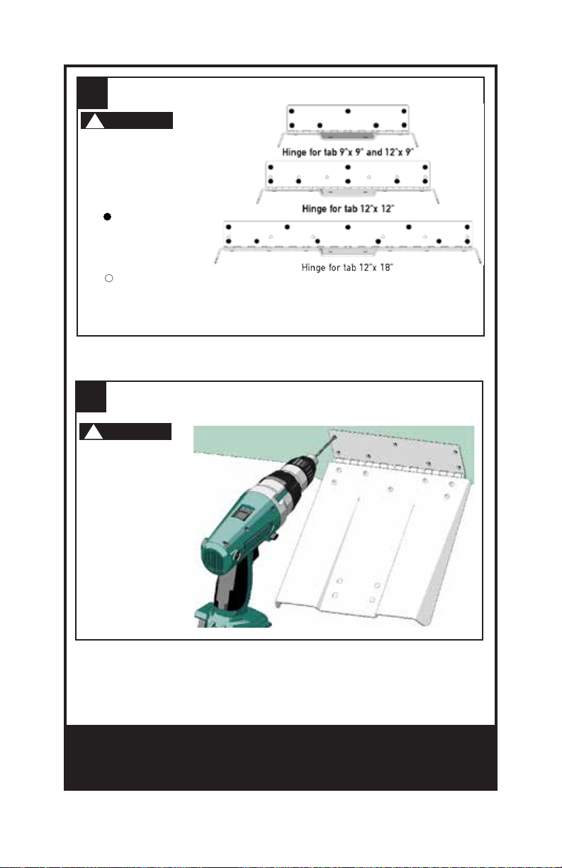
2
3
Locate the hole pattern you will be using.
Mark the hole positions on your transom. Then make
preholes using your 7/32” drill bit.
!NOTICE
!NOTICE
In order to ensure
proper tment and
installation of the
tabs, use the bigger
holes indicated by
the in the picture.
The smaller holes
indicated by
the are used for
installations which
are replacing other
systems.
The holes should
be drilled to a
maximum depth
of 1.25”.
10
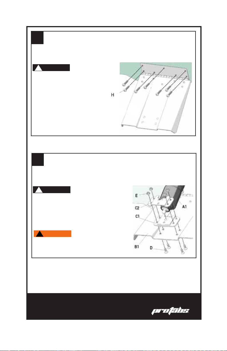
4
5
Put 3M 5200 (or equivalent) sealant into the preholes
and x the hinge to the transom by using the supplied
self-tapping screws (H). Once the hinge has been
xed, apply sealant to the perimeter.
Position the spherical head of the actuator rod (A1)
between the plastic bracket (C1) and the ange (C2).
Fasten the three components to the tab (B1) by means
of the 4 screws (D) and 4 nuts (E).
!NOTICE
!NOTICE
All of the supplied screws are
stainless steel. Never use
any other type of fastener.
The actuator (A1) is provided from the
factory in the fully-retracted posi-
tion. For the installation, it is strictly
necessary not to power it to avoid any
possible position change.
The bracket MUST be installed exactly
as shown in the picture.
!WARNING
TameThe Waves 11
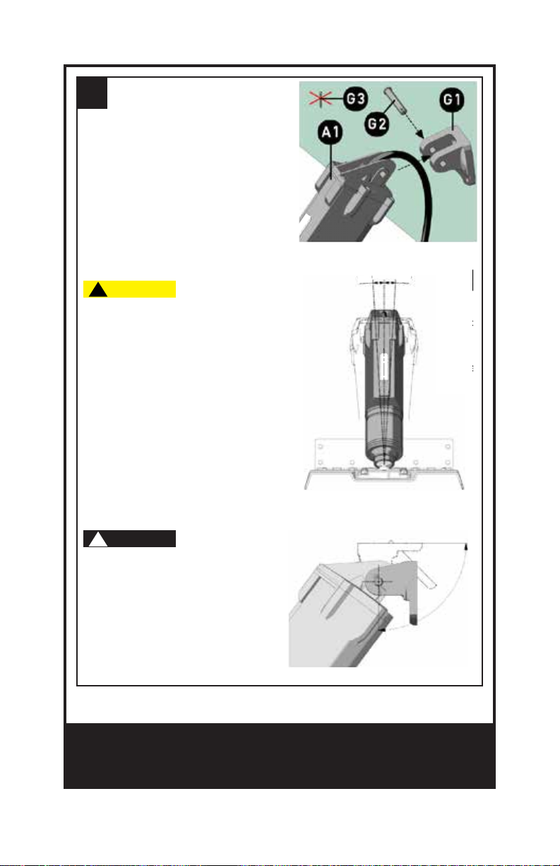
6Insert the upper bracket
(G1) on actuator (A1)
using only the pin (G2)
but NOT the split pin
(G3). DO NOT insert the
cable through the bracket
at this time.
!NOTICE
The upper bracket also allows the
assembly of the actuator in a ver-
tical position. The possible posi-
tions are shown in the picture.
!CAUTION
The bracket on the tab side allows an
articulation of up to 7 degrees of the
actuator (see image). If this angle is
exceeded for the installation, the upper
bracket may break.
3.5° 3.5°

12
7Place the upper
bracket (G1) on the
transom.
Once the tab is properly positioned,
use a permanent marker to trace the
loation of the upper bracket.
!NOTICE
For a correct installation,
lift the outer edge of the tab
according to the measurements
which are shown in the
following table.
INSTALLATION DISTANCE
AB
27/32”
25/32”
9”
12”
8Remove the upper bracket (G1) from the actuator (A1)
and place it on the transom, aligning it with the marks
you made in Step 7. Then mark the hole positions
with a permanent marker.
!NOTICE
Make sure the cable hole
is properly positioned.
1.15”

TameThe Waves 13
9
10
Make three 7/32”
holes at least 1”
deep to x the
bracket (G1) and
one 25/64” hole in
the center to allow
the passage of the
power cable.
Insert the upper bracket (G1) on the actuator (A1) by
using the pin (G2), the washer (G4), and the split pin
(G3) supplied. Make sure you have passed the power
cable (1) through the center hole in the bracket.
Insert the power cable into the transom hole. Place
sealant in each of the three screw holes, around the
power cable hole, and on the back side of the bracket.
14
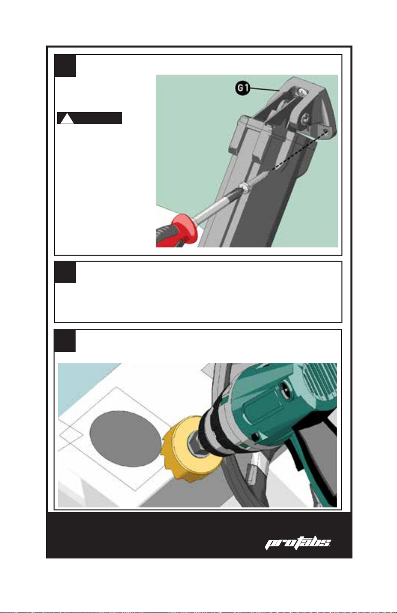
11
13
12
Fix the upper bracket (G1) by means of the supplied
screws.
Mark your hole location and cut it out with a
2.75” hole saw.
Refer to the joystick dimensions on pg. 6
or cut out and use the diagram on pg. 23
to determine where you will mount your
joystick.
!NOTICE
Wait for the sealant
to dry. Proper
dry-time will be
dependant on brand
of sealant used and
should be found on
the packaging.
1.15”

TameThe Waves 15
14
15
Assemble the joystick as shown below. There
is a small hole in the face of the koystick and
a small knob on the back of the faceplate.
Lining these up will allow you to install the
joystick properly.
Position the joystick where you want it and
use the 4 supplied screws to secure it in
place.
!NOTICE
You must install
the plastic bezel
to prevent the
faceplate from
coming loose and
falling o.
16
Wiring Overview
COLOR DESC. USE SIZE
RED +BAT POSITIVE POWER WIRE AWG 14
AWG 14
AWG 16
AWG 16
AWG 16
AWG 16
AWG 18
AWG 18
AWG 18
AWG 18
AWG 18
AWG 18
AWG 18
AWG 18
NEGATIVE POWER WIRE
STARBOARD ACTUATOR POSITIVE
PORT ACTUATOR POSITIVE
STARBOARD ACTUATOR NEGATIVE
PORT ACTUATOR NEGATIVE
ENGINE KEY
NEUTRAL SAFETY NEGATIVE
NEUTRAL SAFETY POSITIVE
SECOND STATION COMMON
SECOND STATION CONTROL
SECOND STATION CONTROL
SECOND STATION CONTROL
SECOND STATION CONTROL
GND
STB+
PORT+
STB-
PORT-
KEY
NSAF-
NSAF+
COM
UP
DOWN
LEFT
RIGHT
BLACK
WHITE/GREEN
WHITE/RED
BLACK/RED
BLACK/GREEN
ORANGE
ORANGE/WHITE
ORANGE/BLACK
BLUE
YELLOW
GRAY
PURPLE
GREEN
!WARNING
All wiring should be performed by skilled technicians. POWRTRAN
INC is not to be held responsible for possible damages or malfunctions
deriving from improper wiring.
The extension cables provided have color-coded zip ties indicating
their particular use:
• GREEN=Starboard Actuator Extension
• RED=Port Actuator Extension
• BLACK=Power Cable Extension
!NOTICE
Cable Identication
The following table provides a quick guide to the wires that come o
of the joystick control.

TameThe Waves 17
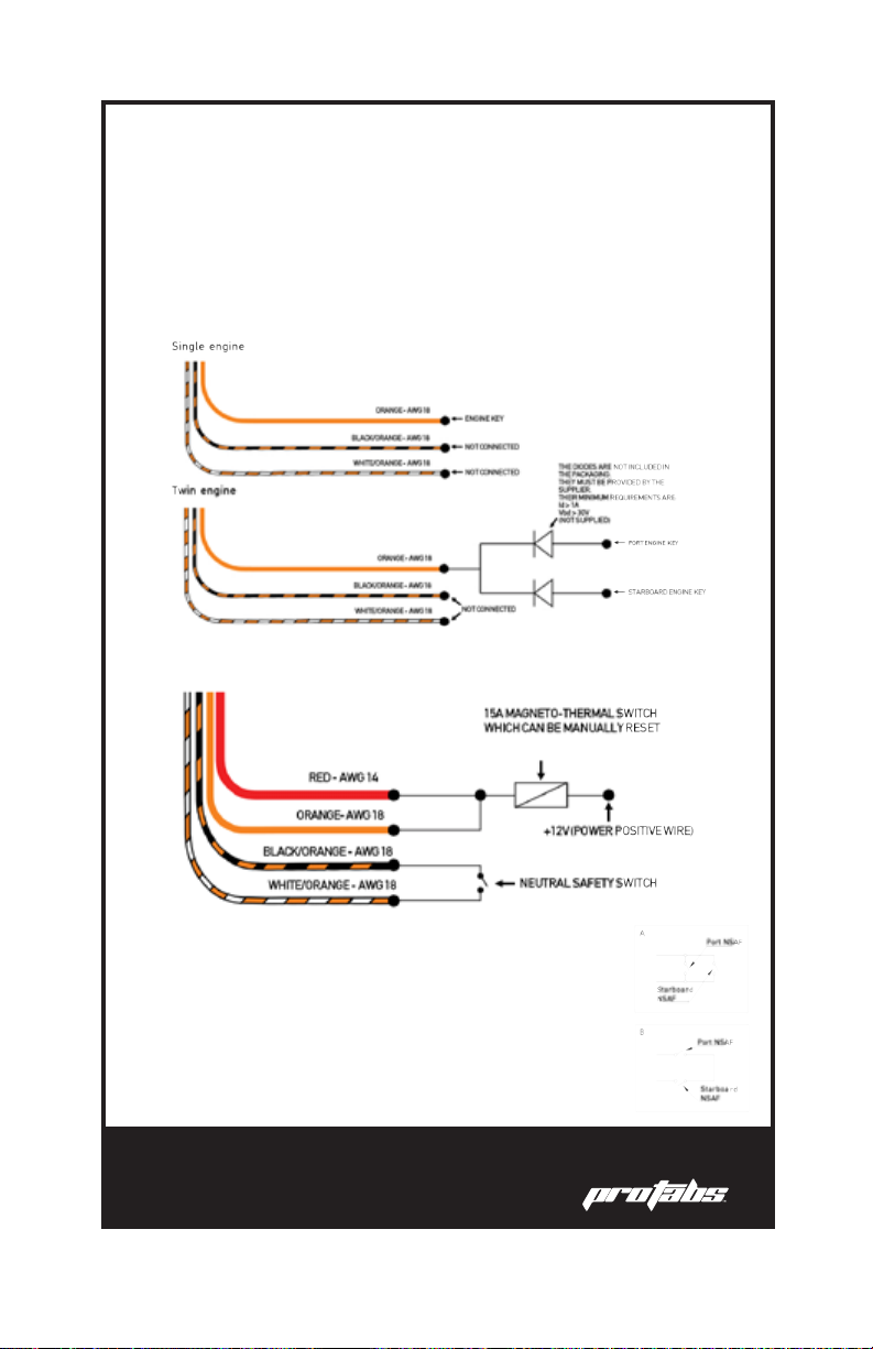
Wiring Diagram
18
Auto Line-Up
When running at idle, or when the engine turns o, the auto line-up
puts the tabs in rest position (all the way up) automatically.
The auto line-up function can be enabled by means of the panel key or
the neutral safety switch of the control unit.
Engine Key
Neutral Safety Switch
Twin Engine
In case of twin engine boats with two dierent neutral safety
switches, the auto line-up can be enabled in two ways:
A. The auto line-up is enabled when at least one of the two
engines has not been put into gear.
B.The auto line-up is enabled when both engines have not
been put into gear.
TameThe Waves 19
Maintenance
Proper maintenance is an important factor for the safety and life of
your Pro Tabs. Only skilled and properly trained sta should carry out
maintenance operations.
The design and materials used to manufacture the Pro Tabs reduce
maintenance operations to a minimum.
Technical Support
For Technical Support, please contact Powrtran Inc. at
!WARNING
!WARNING
The main safety warnings to be observed during maintenance are:
• DO NOT wear rings, watches, etc. during maintenance
operations.
• ALWAYS wear gloves and proper eye protection.
• DO NOT use free ames, sharp edges, or pins for cleaning.
• DO NOT smoke.
Before the beginning of each season, check that:
• Fixing screws are rmly fashioned.
• There is no marine growth on the actuator or any moving parts.
To discourage any marine growth on tab, antifouling paint can be
applied. When applying the paint to the actuator, make sure it is
fully retracted.
!NOTICE

20
Trim Tab Use
The electronic system can automatically enable an important function
named “Auto line-up” which allows aligning of the tabs at rest without
using the joystick.
As explained in the Wiring section, two dierent kinds of installation
are available; Engine Key Control or Neutral Safety Switch Control.
This function is provided with an inhibition device that prevents
it from being enabled again for ve minutes. After this time has
passed, the “Auto line-up” function is available again.
If, for any reason, you wish for the joystick control to behave opposite
of this setup, that can be achieved by reversing the position of the
black and white actuator wires.
The Pro Tabs were designed for a simple, intuitive operation and can
even be used by individuals who are not familiar with other trim tab
systems.
The Pro Tabs are controlled via a joystick which allows for single-
handed operation. Both tabs are controlled by jogging a single
joystick, making it easier than ever before to control the boat.
The joystick can be manipulated into four positions. The four possible
positions are illustrated on the next page. They are:
• By jogging the joystick forward, the bow of the boat is pushed
down, forcing the boat into a planing position.
• By jogging the joystick backward, the bow of the boat is raised,
reversing the planing position.
• If the boat is listing starboard, jogging the joystick to the left will
level the boat.
• If the boat is listing port, jogging the joystick to the right will
level the boat.
Table of contents
Popular Boating Equipment manuals by other brands


Uflex
Uflex UC 69-I Installation and maintenance manual

VariProp
VariProp DF-80 Assembly and operating instructions

GEMLUX
GEMLUX FLY SH ADE instructions

Vetus
Vetus BOW22024C Operation manual and installation instructions

CIPTA PERNIKA NUSANTARA
CIPTA PERNIKA NUSANTARA SMART VMS manual

Lewmar
Lewmar V700 Owners installation, operation & servicing manual