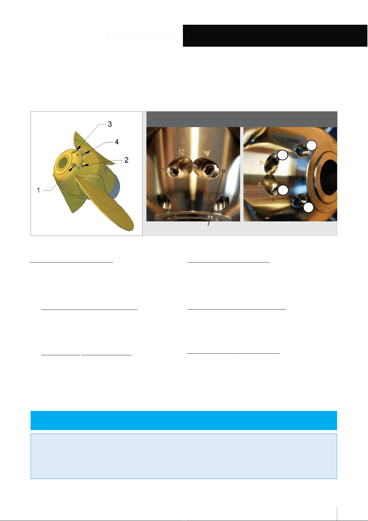
VariProp DF-80 User manual

2-, 3- and 4-blademodel
VARIPROP DF/GP-80 & DF/GP-107
Assemblyand operating instructions for the
F51 DFGP80-107 Installation Instruction_Rev14
Stand: 28.10.2020

2
Notes
14
Tightening torques for the propeller nut
.....................................................................
13
Instructions for recharging .......................................................................................................... 12
Maintenance and Servicing ..........................................................................................................
11
Removal from the shaft after long term use
( after 3rd season)
10
Removal from the shaft after short use
(one or two seasons)
9
Defining and checking the pitch setting
....................................................................
8
Stepless pitch adjustment „RH“...........................................................................................
7
Stepless pitch adjustment „LH“
...........................................................................................
6
Operation ..................................................................................................................................
5
Installation on the Saildrive
........................................................................................................
4
Installation on the shaft
..............................................................................................................
3
"y"
and with yours custom set pitch.
You receive your VARIPROP factory assembled and ready for installation, balanced, greased
Thank you for the trust you have placed in us by purchasing a VARIPROP feathering propeller

3
3
1
2
4
Fig.1
The VARIPROP must not be dismantled, otherwise the warranty claim will expire!
y y
INSTALLATION
Remove the zinc anode (2) and the nut (4) Fit the propeller onto the
that the hub slides completely onto the shaft (see below)
the propeller hub Take care that the key is the proper dimension and
Before fitting the VARIPROP onto the shaft, check key and keyway in
vertically to see it.
must be shining through on the top of the key when looking into the hub from astern.You may have to move your eye
the sides of the key and must be filed or grind slightly down in width or height to avoid problems such as vibrations! Light
the shaft nut very strongly ( torque-setting see page 11 ) the mark must disappear.If not, the key is binding and the top or
MOUNTING: First slide the prop on the shaft without key.Mark the shaft with a grease-pen at the prop end.After tightening
the three tapped holes must be used
of the shaftnut flange A
At least one of
be used, depending on the final position
Only two of the three lockpin holes can
yy
only If over tightened they may strip
nut a little The lockpins should be hand tightened
little further until they do If impossible, back off the
go in easily If not, try first to tighten the propnut a
Carefully align the lockpins (3) straight They must
fitted onto the shaft! The VARIPROP needs water pressure on the blades, otherwise the prop could be damaged!!
Y Please consider that the dry test of the engine MUST NOT be done while the VARIPROP is
M5x16 (DF/GP-80)
stop. The shockabsorber function can be felt ! See servicing page 11.
check that the bladesrotate freely from the forward stop to the reverse
necessary in freshwater.After the VARIPROP has been fitted properly
corrosion by changing the anode (2) latest every year! May not be
Make sure that the propeller is always protected from electrolytic
Lock Pin DF/GP-107 --> M6x16 (DIN914)
Notice: Lock Pin DF/GP-80 --> M5x16 (DIN914)
Fit the anode (2) with 3 off M5x20 (DIN912). Do not use longer length!
the shaft ( torque-setting see page 11 ) and secure it with the lock pins (3).
shaft strongly.Tighten the nut (4) with LOCTITE low (pink) onto
M5x20
DIN 912-A2
M6x16
DIN 914-A2
(DF/GP-107)

4
3
1
2
4
5
Fig.1
TLI:%6-4634QYWXRSXFIHMWQERXPIHSXLIV[MWIXLI[EVVERXyGPEMQ[MPPIxpMVI
y y
I
stop to the reverse stop The shock absorber function can be felt ! See servicing page 11
less often in fresh water After the VARIPROP has been fitted properly check that the blades rotate freely from the forward
lock pins (3) Hand tighten only, and then mount the zinc cone
( 2 ( M8x45 DF80 / M8x60 DF107 / 15Nm / 10ft/lb) and two
Secure the propeller nut (1) with the hexagonal socket cap screw
saildrive to reduce it The spacer discs are delivered with the prop
different spacer disc between the forward end of the prop and the
the prop on the saildrive shaft If it is too high, fit one or more of the
After installation, check that there is only a little end clearance for
used
one ofthe three tapped holes must be
positionof the shaftnut flangeAt least
canbe used, depending on the final
Only two of the three lockpin holes
using the three screws (5)
Finally screw the zinc cap onto the propeller by
tightenedonlyIf over tightened they may strip
back off thenut a littleThe lockpins should be hand
propnut alittle further until they doIf impossible,
mustgo in easilyIf not, try first to tighten the
Carefully align the lockpins (3) straightThey
electrolytic corrosion by changing the zinc anode (4) latest every year,
( see beside ) Make sure that the propeller is always protected from
Washer
Saildrive manufacturer before tighten the prop nut (1).
Observe the recommended torque settings of the
SD 40/50 100Nm / 75ft/lb ) and use loctite low (pink).
the spline. Tighten nut (1) strongly ( 60Nm / 45ft/lb; Yanmar
propeller nut (1) the propeller hub will slide completely unto
the spline. After removal ot the zinc anode (4) and the
required to find the exact position where the hub slides unto
avoid on-axis movement. Some careful “wiggling”may be
with the saildrive spline grooves. Tolerances are very tight to
spline, please check if the propeller hub gears mate precisely
Before mounting the VARIPROP properly onto the saildrive
M5x20
DIN 912-A2
M6x16
DIN 914-A2
Schnorr-
Sicherungsscheibe

5
Y
blades will engage in either forward or reverse
The VARIPROP feathers automatically when the shaft rotation is stopped After engine startup and shifting into gear the
reverse to stop the freewheeling of the shaft
»•Stop the engine and engage the transmission in
»•Power at 3 to 4 knots in forward
with mechanical gear-box:
sailposition
position.
spinning the shaft to feather the blades in the sail
remaining oil pressure of the transmission will stop
»•Stop the engine while still engaged in forward The
»Power at 3 to 4 knots in forward.
with hydraulic transmission:
sailposition
If the propeller does not work in forward or reverse go systematically through the points below:
feather You can actually use this feature to drive a shaft generator
the engine while it turns in reverse In this case the blades will stay in the reverse position and will not
Once the prop is feathered , it is better to shift the transmission to neutral
In that case start the engine again and repeat the steps above
If the propeller is not feathered in the sailposition the shaft will freewheel like with a fixed propeller
amount of lever travel is in no way detrimental.
in the owners manual of your transmission A larger
end positions for forward and reverse can be found in
of the actuating lever, between the neutral position and
amount of lever travel, as measured at the pivot point
Make sure that the shifting travel is not too short.The
»•Check shifting movement of the transmission lever
in idle
»•Check low idle of the engine It should be 800 to 900 rpm
(available by SPW only!)
filled with ours special EP/SAL grease
»Make sure that the VARIPROP is always sufficiently
could be worn out
»•Check the clutch discs of the transmission They
VARIPROP.
blades. This is normal and not a problem or a defect of your
opposite, you can hear the turning-noise of the feathering
propeller gears. When going from ahead to astern or the
binding.This will substantially lengthen the service life of your
between gears to allow smooth reversing of rotation without
necessary to idle down and shift at low rpm's (max.1200rpm)
»When going from ahead to astern or the opposite, it is
and ensure a long service life:
using the VARIPROP in order to avoid unnecessary damage
It is important to observe the following when
of the anode once a year
plus the prop anode We recommend the replacement
corrosion by fitting the usual zinc anodes on the shaft
» The propeller must be protected from electrolytic
approved service centres.
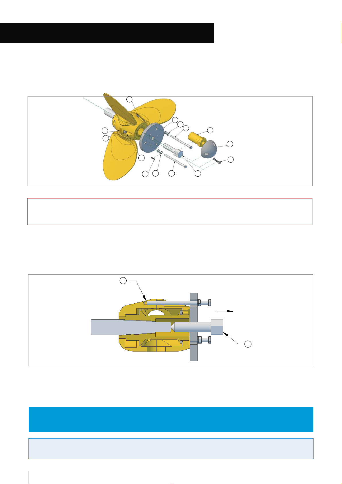
technical know-how only available at the factory or their
Disassembly and reassembly require special tools and
»Never dismantle the VARIPROP yourselves !!
from your VARIPROP distributor.
( offers also protection against electrolyses ), available
recommendation is Velox TF plus including a primer
chemical interaction and decomposition could occur.Our
use only Antifouling which needs a primer first.Otherwise
»If you want to protect your VARIPROP with Antifouling,
servicing page 11 )
TW.2 GEL or mineral multi-purpose grease EP/SAL (see
high viscosity grease We recommend synthetic grease typ
»The propeller body must always be completely filled with a

6
Fig.2
1
2
4
3
pitch adjustment
Markings to check and determine degree of
adjustment markings
The following description refers to the view towards astern for a VARIPROP.
Lock set screw strongly.
»Secure set screw with LOCTITE-Low (pink).
( see “NOTE”and page 8)
»Turn the adjusting screw anti-clockwise.
2b. Reducing of pitch approx. 2“ max.
Lock set screw strongly.
»Secure set screw with LOCTITE-Low (pink).
( see “NOTE”and page 8)
»Turn the adjusting screw clockwise.
2a. Increasing of pitch approx. 3“ max.:
“V” (=ahead) with the 5mm Allen-key as follows:
2. Turn the adjusting screw , which is marked as
Under water: only 3 turns loosen
1. Remove the set screw (1/4mm allen key)
Lock set screw strongly.
»Secure set screw (3) with LOCTITE-Low (pink).
( see “NOTE”and page 8)
»Turn the adjusting screw (4) clockwise.
2b. Reducing of pitch approx. 3“ max.
Lock set screw strongly.
»Secure set screw (3) with LOCTITE-Low (pink)
( see “NOTE”and page 8)
»Turn the adjusting screw (4) anti-clockwise.
2a. Increasing of pitch approx. 2“ max.:
Under water: only 3 turns loosen
1. Remove the set screw (3) (1/4mm allen key)
The pitch adjustment is very simple on the VARIPROP, and can be done in or out of the water in matter of few
(1) &
minutes, if a there is enough space between propeller hub and strut to fit an allen key into the set screws
(3) at Fig2 If not, the propeller must first be pulled (see removing from the shaft page 9 and 10)
R= AS (Astern) / reverse V= AH (Ahead) / forward
Propeller in the drawing below (Fig.2) is for a left hand rotation VARIPROP „LH“.
Required tool for pitch adjustment see page 12 (Tightening torques)
revolution by approx.200.
the adjusting screws (2) and (4) by half a revolution ( 180° ) changes the pitch approx. 1“. This will change the engine
NOTE: It is quite possible to set the pitch continuously variable and independently for forward and reverse. Turning of
set screws (1 & 3)
adjusting screws (2 & 4)
“R” (=astern) with the 5mm Allen-key as follows:
2. Turn the adjusting screw (4), which is marked as

7
Fig.3a
1
2
4
3
Propeller in the drawing below (Fig.3a) is for a right hand rotation VARIPROP
„R
H
“
.
R= AS (Astern) / reverse V= AH (Ahead) / forward
degree of pitch adjustment
Markings to check and determine
adjustment markings
The following description refers to the view towards astern for a r
right hand
VARIPROP
Adjusting the forward pitch :A.
»Secure set screw (
(1)
with LOCTITE-Low (pink).
( see “NOTE”and page 8)
» Turn the adjusting screw (2) anti-clockwise.
2b. Reducing ofpitch approx. 2“ max.
2a. Increasing ofpitch approx. 3“ max.:
“V” (=ahead) with the 5mm Allen-key as follows:
2. Turn the adjusting screw (2) which is marked as
Under water: only3 turns loosen.
1. Remove the set screw (1) (1/4mm allen key).
Under water: only3 turns loosen.
1. Remove the set screw (
(3)
(1/4mm allen key).
B. Adjusting the reverse pitch:
Required tool forpitch adjustment seepage 12 (Tightening torques)
change the engine revolution by approx.200.
Turning of the adjusting screws (2) and (4) by half a revolution ( 180° ) changes the pitch approx.1“.This will
NOTE: It is quite possible to set the pitch continuously variable and independently for forward and reverse.
(1) & (3) atFig 3a. Ifnot,thepropeller must first be pulled. (see removingfrom the shaftpage 9 and 10)
few minutes,if there is enough space betweenpropeller hub and strut to fit an Allen keyinto the set screws
GENERAL: The pitch adjustment is verysimple on the VARIPROP, and can be done in or out of the water inamatter of
set screws (1 & 3)
adjusting screws (2 & 4)
( see “NOTE”and page 8)
» Turn the adjusting screw (2) clockwise.
Lock set screw strongly.
» Secure set screw (1) with LOCTITE-Low (pink)
( see “NOTE”and page 8)
» Turn the adjusting screw (4) anti-clockwise.
Lock set screw strongly.
» Secure set screw (3) with LOCTITE-Low (pink)
( see “NOTE”and page 8)
» Turn the adjusting screw (4) clockwise.
Lock set screw strongly.
»Secure set screw (
(1)
with LOCTITE-Low (pink).
Lock set screw strongly.
2a. Increasing of pitch approx. 2“ max.:
2b. Reducing of pitch approx. 3“ max.
“R” (=astern) with the 5mm Allen-keyas follows:
Turn the adjusting screw (
(4)
which is marked as2.

8
markings on the hub face.
on the hub face under the zinc anode. To return to original factory pitch settings, line up “AH” or “V” resp. “AS” or “R”
quarter turn ( 90° ) changes the pitch by ½” and a one full turn by 2” etc.. For a check of pitch adjustments there are markings
adjusting screws (2) & (4) in Figure 2 & 3a ( see pages 5&6 ) by half a revolution changes the pitch approx. 1“. That means a
It is quite possible to set the pitch continuously variable and independently for forward and reverse. The turning of the
Example for ahead:
The example shows adjustment of +1"
Marked with „ V “ !
Check adjustments ahead!
pitch has been increased ahead
Example for ahead:
markings line up
original factory pitch setting :
Marked with „ R “ !
Check adjustments astern! The example shows adjustment of 1"
markings line up
original factory pitch setting : pitch has been decreased astern
»1” of pitch reduction / increase results in approx 200 engine revolutions increase / reduction
»If the engine exceeds the desired RPM increase the pitch
»If the engine does not reach the desired RPM reduce the pitch
Note:

9
Fig.4
10
5
5
10
9
7
7
8
6
1
Fig.3
9
6
1. In order to remove the VARIPROP you must first remove the zinc anode (2).
2. Remove both lock pins (3) and the prop nut (4)
4
3
2
Take care that plate (6) will fit snugly and evenly to the aft boss.
onto the aft of the rear boss and screw the short hexagonal head screws (7) completely into the zinc screw holes (10).
3) Fit the short hexagonal head screws (7) into the inner bolt circle diameter of the puller (6)Fit the SPW puller (6)
It would dismantle the two separate halves of the VARIPROP hub !!!
DO NOT OPEN THE HEXAGON SOCKET SCREWS (5) !
CAUTION!
Never use a hammer to remove the prop from the taper !!!
excessive force to turn bolt (9).If prop does not come off, proceed to page 10 –> removal after the 3rd season.
4 Now turn the hexagonal head bolt (9) against the end of shaft until the VARIPROP comes off the taper.Do not use
Standard 3-prong pullers can easily slip and damage the rounded VARIPROP housing !
We highly recommend the use of above described special puller, available from your VARIPROP dealer.
assembly requires special knowledge and special tools.
CAUTION: The VARIPROP should NOT be dismantled into its individual parts! The correct

10
9
3
10
5
5
89
11
7
7
8
6
1
2
4
11
Fig.4
2.
1.
VARIPROP removal after 3 years or more.
In order to remove the VARIPROP you must first remove the zinc anode (2).
Remove both lock pins (3) and the prop nut (4)
Standard 3-prong pullers can easily slip and damage the rounded VARIPROP housing !
We highly recommend the use of above described special puller, available from your VARIPROP dealer.
with LOCTITE blue ( medium ).Take care that the hub halves do not come apart when removing the hexagonal head srews (7).
6. At the end remove the puller (6) carefully and secure the boss halves (10) with the socket screws (5).Tighten strongly
hammer to remove the prop from the taper !!!
5. Now turn the hexagon head bolt (9) against the end of shaft until the VARIPROP comes off the taper.Never use a
will fit snugly and evenly to the aft boss.
remove the last hexagonal socket screw (5) as well and fit the third long hexagonal head screw. Take care that plate (6)
and evenly to the aft boss. CAUTION: Do not dismantle the two separate halves of the VARIPROP hub !!! In this mode
screw holes (11) of the front boss halve (10).Tighten the nut (8) on the head screws (7) until the plate (6) is fitted snugly
Now fit the SPW puller (6) onto the aft of the rear boss and screw the long hexagonal head screws (7) completely into the
4.Fit two of the long hexagonal head screws (7) into the outer bolt circle diameter of the puller (6).
that the VARIPROPhub-housing remains together.
other and immediately secure one after the other with the long screw of the puller so
Do not remove all housing screws (5) at the same time, but loosen one after the
3. Then remove at first only two hexagonal socket screws (5).DO NOT OPEN ALL!!
The correctassembly requires special knowledge and special tools.
CAUTION: The VARIPROP should NOT be dismantled into its individual parts!

11
ANY WARRANTY IS VOID!
This concerns in particular the installation of the anodes.Non-original SPW anodes lead to malfunctions!
anodes -screws -locking screws and EP/SAL special grease
We explicitly point out that the following spare parts may only be installed as original SPW parts:
Important note:
anode drill holes on top of the prop.
stop to reverse stop to allow the grease to work through the propeller. Stop to pump when enough grease comes out of the
supplied with the tools. Further remove the zinc anode! With each pump of the grease gun rotate the propeller from forward
with a high viscosity grease of a hydrophobic nature. Remove the cap screw (5) and screw in the lubricating nipple which is
The VARIPROP needs to be greased a minimum of once a year. The VARIPROP body should always be completely filled
out here!
grease squeeze
Stop greasing if
nipple M5
Lubrication
Cap-screw (5)
regular white grease (sterntube-grease ) !
Factory supplied special grease EP/SAL is recommended and available from your VARIPROP distributor.Avoid
“heavy” turning at the absorber area is normal and necessary for the function !
substantially protected against wear.At rotating the blades by hand, you can feel the shock-absorber function.This
The integrated shock-absorber reduces unpleasant operating noises.The pitch stops are
VARIPROP-anode to give the zinc good contact with the propeller
use a zinc anode onto the shaft if possible.Use fine sandpaper to clean the aft of the end boss and the forward face of the
Make sure that you always keep the zinc anode in good condition.The VARIPROP must be protected by a lot of zinc, so also

Stop of recharging
too fast in ahead during this manoeuvre!
To avoid consequential damage to the drive system make sure that you don't drive
-» Go into the wind and reduce the sailing speed to below 4 knots!
-» Make sure that the gearbox is in the "neutral" position while you start the engine.
operating instructions for the VariProp (page 5).
the sailing position. For hydraulic transmission see also chapter "Use" in the installation and
reverse (with mechanical gearbox), to stop the shaft from spinnig. The VariProp feathers into
sailing and stop the engine. When the engine is switched off, the gear can be engaged in
-» The VARIPROP moves from its reverse position to the forward position. Now you can resume
-» Now engage into forward gear at the slowest possible ship speed (below 4kn).
reasonably satisfactory energy yield.
As a rule, the boat speed should be over 12 knots or more in order to achieve a
The VARIPROP can only be used to a limited extend for a successful recharging.
»» Now the regeneration can be started.
spinning.
-»
After the engine is turned off, you go by the wind and pick up speed. Check whether the shaft is
Make sure that the engine (gearbox) is not returned to the forward position before switching off.
-» With 2.5 - 3 kn forward speed go into the "neutral position" and switch off the motor.
-»
Now switch the engine (gearbox) to reverse to stop the boat.
In this way you avoid unwanted damage to the drive system (shaft unit; gear box, etc.)
Please make sure that a maximum speed of 4-5 knots is not exceeded.
-» After the sails are set, walk in the wind and stop the ship.
-»
Go ahead and initiate the setting of sails.
12
NOT suitable for saildrive drives!
INSTRUCTION FOR USING A VARIPROP
FOR RECHARCHING (shaft drive)

M 14 x 2
UNC 1/2 “ -13
40 Nm
M 16 x 2
BSW 5 / 8 “ - 11
UNC 5 / 8 “ - 11
60 Nm
M 16 x 2
Für Yanmar Saildrive SD 20 und SD 31
und für alle Volvo Saildrive
60 Nm -
70 Nm
M 20 x 2,5
BSW 3 / 4 “ - 10
UNC 3 / 4 “ - 10
125 Nm
160 NmUNC 7 / 8 “ - 9
M 24 x 3
BSW 1 “ - 8
UNC 1 “ - 8
210 Nm
M 14 x 1,5
BSF 1/2 “ - 16
40 Nm
M 16 x 1,5
BSF 5 / 8 “ - 14
UNC 5 / 8 “ - 18
70 Nm
M 20 x 1,5
BSF 3 / 4 “ - 12
UNC 3 / 4 “ - 16
135 Nm
M 20 x 2
Für Yanmar Saildrive
SD 40 und SD 50
100 Nm -
120 Nm
M 24 x 2
BSF1 “ - 10
UNF 1 “ - 12
225 Nm
+
+
(see page 3, Fig. 1,part no. 4)
Fine – threadStandard – thread
Tools supplied with each VARIPROP
(pink)
»»1 small plastic bottle with Loctitelow
»»1 allen key4 mm
»»1 allen key3 mm
»»1 grease nipple 5mm
»»1 allen key5 mm
»»1 allen key 5 mm
»»1 allen key 4 mm
»»1 allen key 2 mm
»»1 grease nipple 5mm
(pink)
»» 1 small plastic bottle with Loctitelow
»»1 allen key4 mm
»»1 allen key3 mm
»»1 open-end- / box spanner 36mm
»»1 open-end- / box spanner 8mm
»»1 allen key 4 mm
»»1 allen key 2 mm
»»1 open-end- / box spanner 32mm
»»1 open-end- / box spanner 8mm
for DF/GP-107:
for DF-80:
necessary tools for removing the prop after 3 years (page 10)
»»1 open-end- / box spanner 32mm
for DF-80:
»»1 open-end- / box spanner 13mm
»»1 allen key 2 mm
»»1 allen key 4 mm
»»1 allen key 5 mm
»»1 open-end- / box spanner 36mm
»»1 open-end- / box spanner 13mm
»»1 allen key3 mm
»»1 allen key4 mm
»»1 allen key6 mm
»»1 allen key5 mm
Service tool for
Service tool for
»»1 allen key 4 mm
»»1 allen key6 mm for socket cap screw (2)
extra for Saildrive (Fig.1/p.4)
necessary tools for removing the prop after 1 or 2 seasons (page 9)
Service Tools DF/GP-107
(Fig.1):
Service Tools DF/GP-80
(Fig.1):
for DF/GP-80:
for DF/GP-80:
Service tool for
Service tool for
13
TORQUE SETTINGS FOR PROP-NUT
Pitch Adjustment DF/GP-80
(Fig.2/3a):
Pitch Adjustment DF/GP-107
(Fig.2/3a):
for DF/GP-107:

NOTES
14

Made in Germany
Westkai 58 | 27572 Bremerhaven
Telefon +49 (0) 471 - 7 70 47
Telefax 0471 - 7 74 44
www.spw-gmbh.de | www.VARIPROP.de
OnlineShop
Other manuals for DF-80
1
This manual suits for next models
3
Table of contents
Popular Boating Equipment manuals by other brands

Wichard
Wichard ProFurl NEXE 5.0V12 installation manual

MINN KOTA
MINN KOTA TALON manual

Classic Accessories
Classic Accessories WAVEGEAR instructions

SmartGyro
SmartGyro SG40 Operation manual

Forespar
Forespar Leisure Furl OFFSHORE IN-BOOM FURLING SYSTEM installation manual

MAX PROP
MAX PROP Easy Manual of Instruction

Hobie
Hobie Getaway Hatch instructions

NovaSail
NovaSail NS100 operating manual

Torqeedo
Torqeedo 1918-00 operating manual

DockCraft
DockCraft The DockSider 400 Series Assembly, installation and operating instructions

Vetus
Vetus BOW35 Series Installation Recommendations

C-Nav
C-Nav C-Nav3050 quick start guide