PPM ViaLite MINI User manual

OUTDOOR ENCLOSURE TYPE MINI HANDBOOK
2
Instrument Care and Safety Information
Please read the whole of this section before using your ViaLiteHD product. It contains important safety
information and will enable you to get the most from your Fibre Optic link.
Electrical Safety
The ViaLiteHD enclosure is a Safety Class 1 product (having metal chassis directly
connected to earth via the power cable).
When operating the equipment note the following precautions:
Hazardous voltages exist within the equipment.
There are no user serviceable modules inside.
There are replaceable fuses inside the casing. Replacement should only be carried out
by a PPM technician.
The chassis earth stud SHOULD be connected to the safety earth.
When using a 2 pin power supply cable the chassis earth stud MUST be connected to
the safety earth.
The ViaLiteHD Power Supply Modules do not have an isolating switch on the mains
voltage inlet. For this reason, the ViaLiteHD chassis MUST be installed within easy
reach of a clearly labelled dual pole mains isolation switch, which supplies the
equipment.
PSU modules are fused on the mains live feed only. A second fuse should be used for
the neutral connection where the polarity of the connectors can be reversed; rating
should match those given in section 2.13.
ESD Precautions Precautions for handling electro-static sensitive devices should be observed when
handling all ViaLite modules. Technicians should ensure that they use effective personal
grounding (i.e. ESD wrist strap etc.) when servicing the equipment. Any equipment or
tools used should be grounded to prevent static charge build-up. Good practice should be
observed at all times. For reference see relevant standards.
EN 61340-5-1, “Protection of Electronic Devices from Electrostatic Phenomena – General
Requirements”
Optical Safety The ViaLite RF Transmitter and Transceiver modules contain laser diode sources
operating at nominal wavelengths of 1270nm to 1610nm.
These devices are rated as EN60825-1 CLASS 1 radiation emitting devices. A class 1
laser is safe under all conditions of normal use.
When operating the equipment note the following precautions:
Never look into the end of an optical fibre directly or by reflection either with the naked
eye or through an optical instrument.
Never leave equipment with radiating bare fibres –always cap the connectors.
Do not remove equipment external covers when operating.
Hot surface The ViaLite systems may have hot surfaces when operating under full load. The hot
surfaces are not accessible when fitted in an approved chassis installation. Hot surfaces
will be appropriately marked
Suitable precaution should be taken when handling this device.
Allow to cool for 10 minutes
Do not touch metallic surfaces or printed circuit board when hot.

OUTDOOR ENCLOSURE TYPE MINI HANDBOOK
3
When handling, hold front panel and handle only.
TABLE OF CONTENTS
1INTRODUCTION ......................................................................................................................................... 4
1.1 Typical deployment.................................................................................................................................4
1.2 ViaLiteHD compatibility..........................................................................................................................4
1.3 Care of fibre optic connectors.................................................................................................................4
1.4 Fibre optic cable & connectors ...............................................................................................................5
Connector and cable types...........................................................................................................5
Connecting and disconnecting.....................................................................................................5
Cleaning optical connectors, cleaning before every use..............................................................5
Cleaning optical connectors, high levels of contamination ..........................................................5
SC/APC Connectors.....................................................................................................................6
Minimum bend radius...................................................................................................................6
2SETTING UP THE ODE-MINI...................................................................................................................... 7
2.1 ODE-MINI external features ...................................................................................................................7
Humidity control/ventilator gland..................................................................................................7
2.2 Weatherproof interface connections.......................................................................................................8
2.3 Mounting the ODE-MINI .........................................................................................................................9
Using the 70004-2 wall mounting bracket kit ...............................................................................9
Using the 70004-(60MINI) (90MINI) (110MINI) pole mounting kit ...............................................9
2.4 Lightning Suppressor............................................................................................................................10
2.5 Antennas...............................................................................................................................................11
2.6 Termination of RF Connections............................................................................................................11
2.7 Termination of power............................................................................................................................13
2.8 Termination of Optical fibre ..................................................................................................................14
2.9 LNB Voltage selection ..........................................................................................................................15
LNB Customer variable voltage source......................................................................................16
LNB Voltage tolerance ...............................................................................................................17
2.10 High voltage or High power LNB/BUC supply options .........................................................................17
2.11 ODE-MINI power supplies....................................................................................................................17
2.12 Replacement of Power Supply Modules ..............................................................................................17
2.13 ODE-MINI replaceable fuse..................................................................................................................18
3PRODUCT WARRANTY............................................................................................................................ 19
4FCC APPROVAL ....................................................................................................................................... 20

OUTDOOR ENCLOSURE TYPE MINI HANDBOOK
4
1 Introduction
The Outdoor Enclosure type MINI (ODE-MINI), is a cost-effective weatherproof enclosure for ViaLiteHD
systems and associated hardware. It is intended to service the requirements of most GPS timing and satellite
communication systems though can be configured to suit a wide range of other applications.
The ODE-MINI system is comprised of the following key parts:
IP-65 rated external enclosure fitted with:
Dual power supplies (redundancy or power sharing)
Capacity for up to two ViaLiteHD OEM modules with front panel connections
Termination of input power cable (inside the supplied quick release latching connector)
Patch box for termination of optical cable (various quad fibre cable lengths available)
Connectorised RF inputs / outputs.
It has a wide range of optional accessories including:
Lightning suppressor(s)
Optical cable
Wall or pole mount fixings.
ViaLiteHD RF Fibre Optic Links (FOLs) are a family of fibre optically coupled link systems designed for the
transmission of RF analogue signals over long distances for the communications market.
ViaLite is a product brand manufactured by Pulse Power and Measurement Ltd (PPM).
ViaLite Communications is a division of Pulse Power and Measurement Ltd (PPM).
1.1 Typical deployment
A typical system operates as follows.
The ODE-MINI would house a set of FOL TX modules, in a remote outdoor location connected to antenna
equipment. Antenna electrical signals are input to the transmitter modules, which contain RF signal
conditioning and laser control circuitry. The modules modulate the intensity of a beam of light with the RF
signal for optical transport over a fibre optic cable.
The light travels through the optical fibres to corresponding receiver modules. The distance between
transmitter and receiver can range from 1 m to 100 km; distance in excess of 100 km can be achieved with
more complex optical transport systems, depending on the system specified.
The receiver module converts the modulated light back into an electrical signal, which is available at its
output.
1.2 ViaLiteHD compatibility
The RF and optical interfaces are compatible with all ViaLiteHD Blue modules.
Contact ViaLite Communications or your local ViaLite agent for more details.
1.3 Care of fibre optic connectors
When the fibre optic cables are not connected, it is essential that the cable and equipment connectors are
protected by the dust caps provided with the system. Failure to do so may result in damage to the fibre ends,
which are critical to the system performance. Please refer to section 1.4 for fibre optic cable handling details.

OUTDOOR ENCLOSURE TYPE MINI HANDBOOK
5
1.4 Fibre optic cable & connectors
Connector and cable types
All ViaLiteHD RF modules use singlemode (9µm/125µm) cable terminated in a range of optical connectors
detailed below. Cross-site fibre optic cables are available from ViaLite Communications as either standard
patch leads or heavy-duty multicore cables.
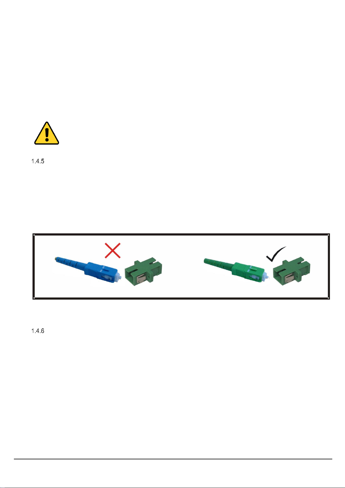
Warning!
Angle polished (APC) and standard (PC) connector must not be confused. The two
connector types are not interchangeable and mating one with the other will damage both the
cable and the module connectors.
The specification of optical connector is critical to the performance of the complete fibre optic
link. System performance can only be guaranteed with fibre optic cables and connectors
supplied by ViaLite Communications. When FC/APC connectors are specified they must
be “narrow key width”.
Connecting and disconnecting
Before connecting optical fibres to the module or to each other, ensure that the mating connectors are clean
(see below).
Cleaning optical connectors, cleaning before every use
Optical connectors MUST be cleaned before use, even where they have been protected with dust caps.
A large percentage of performance issues can be attributed to dirty fibres.
For more details please read the cleaning instruction which accompanies the connector cleaning kit.
Cleaning optical connectors, high levels of contamination
If there are performance issues that are not resolved by basic cleaning in section 1.4.3, then the following
procedure should be used. If the level of contamination is high it will be necessary to repeat this procedure.
Cleaning items required
Lint free fibre cleaning tissues and/or cleaning sticks (normal cosmetic tissues produce dust and are not
acceptable).
Reagent grade Iso Propyl Alcohol (IPA).
Air duster or filtered compressed air line.
Cable Connector Cleaning
Dampen a patch of cleaning tissue with IPA and clean all surfaces of the plug ferrule.
Using a dry cleaning tissue, dry the ferrule and clean the end face.
Using the air duster, blow away any residue from the end of the connector.
Peel the plastic cover from an unused “N”
cleaning pad.
Hold the connector between your thumb
and forefinger
Clean the connector using firm pressure by
swiping in a pendulum motion through each
segment of the “N” shape, following the
diagram
Do not swipe over the same space twice.
OUTDOOR ENCLOSURE TYPE MINI HANDBOOK
6
Module Female Receptacle Cleaning (only recommended if problems are being experienced)
Either use an optical cleaning stick or twist a cleaning tissue to form a stiff probe, moisten either with IPA.
Gently push the probe into the receptacle and twist around several times to dislodge any dirt.
Repeat the above process with a dry tissue.
Using the air duster, blow away any residue from the receptacle.
Important Notes
IPA is flammable. Follow appropriate precautions / local guidelines when handling and storing.
IPA can be harmful if spilt on skin. Use appropriate protection when handling.
It should only be necessary to clean the female receptacles on the modules if problems are being
experienced.
Never inspect an optical fibre or connector with the naked eye or an instrument unless you
are convinced that there is no optical radiation being emitted by the fibre. Remove all
power sources to all modules, and completely disconnect the optical fibres.
SC/APC Connectors
To connect SC/APC optical connectors follow these steps:
Remove the plug protective cover.
Align the connector keyway slot in the adaptor to the key of the plug.
Gently push the plug-into the adapter until a click is heard and the connector locks.
To disconnect follow these steps:
Grip the body of the plug and gently pull the plug from the adaptor, replace the protective cover.
Only connect SC/APC cable to SC/APC.
Minimum bend radius
Because optical fibre is made of glass, it is important not to subject it to excessive stress. For this reason,
each type of cable has a minimum bend radius (MBR) specification, beyond which the cable cannot be bent
without permanent damage occurring.
The minimum bend radius (MBR) of fibre optic cable fitted to ViaLite modules is 50mm. MBR specifications
for ViaLite Communications supplied fibre optic cables are given in the ViaLiteHD RF Link Handbook.

OUTDOOR ENCLOSURE TYPE MINI HANDBOOK
7
2 Setting up the ODE-MINI
This section describes the connections between your ODE-MINI and external systems and steps that must be
taken to set it up. Your ODE-MINI should be delivered preconfigured and ready, but will require connections
to external services. This will generally require that you take the following steps:
Mount the ODE-MINI and the patch box in the required locations
Terminate the fibre connections within the patch box
Terminate the RF connections at the ODE-MINI base plate
Terminate the input power at the ODE-MINI base plate.
2.1 ODE-MINI external features
The ODE-MINI is closed via four M4 screws; this can be torqued with a 4mm AF hexagonal key. The rear
provides fixing points for mounting the unit to either a wall mount plate or a pole mounting kit. The unit may
also be fitted with a solar shield; this is advisable for any application where there may be significant solar gain.
70002-MINI
Wall mount plate for 75010 Outdoor Enclosure, Kit & Fixings
70004-XXXMINI
Pole mounting kit, pole diameter XXX (diameters range from 15 –168 mm)
27520
Lightning Suppressor Kit for Outdoor Enclosure, 1 required per RF Channel
Humidity control/ventilator gland
The enclosure incorporates a side mounted vent that allows the air pressure inside the enclosure to equalise
with the external environment. Furthermore, it allows excess humidity to leave the enclosure whilst preventing
moisture from entering.
Upon installation and sealing of the enclosure, this vent facilitates a stable low pressure differential to ease
stress on the seals and a natural continual drying of the internal humidity for improved reliability of the
electronics.
1. Lid securing screws
2. Serial/Part Number
3. Hinges
4. Securing points for
mounting hardware
5. RF Connections
6. Power connection
7. Duo/Quad Fibre
connection
8. Gore Vent
9. RJ45 Management
Connection
Front view
1
2
1
3
3
5
6
7
Rear view
9
4
4
4
4
6
7
5
8
1
1
8
9

OUTDOOR ENCLOSURE TYPE MINI HANDBOOK
8
It is important to not obstruct / remove or repurpose the vent gland.
2.2 Weatherproof interface connections
To maintain the enclosure’s IP rating, you should observe the following:
The front door should be closed and screws tightened.
All glands should be compressed on to either a cable or blanking rod.
All connectors should be mated to either a matching half or suitable sealing dust cap.

OUTDOOR ENCLOSURE TYPE MINI HANDBOOK
9
2.3 Mounting the ODE-MINI
Using the 70004-2 wall mounting bracket kit
To wall mount your enclosure follow these steps:
Drill holes in wall/ panel as per dimensions in drawing.
Mount screws/ fixing hardware into wall.
Slide Outdoor Enclosure/ Wall Bracket onto position using the keyhole slots.
Once on wall, tighten fixing hardware to ensure assembly is firmly held in situ.
Using the 70004-(60MINI) (90MINI) (110MINI) pole mounting kit
The pole mounting kit comes with installation instructions, see section 2.1, that shows the range of pole
mounting kits available and the pole sizes onto which they fit.
To pole mount your enclosure follow these steps:
Mount the long length of unistrut centrally to the top of the ODE-MINI using the supplied washers and
screws (small).
Mount the short length of unistrut centrally to the bottom of the ODE-MINI using the supplied washers
and screws (small).
Slide one unistrut nut into the top and one into the bottom.
Wrap the pole with the pipe grommet, in the top position.
Slide one end of the clamp into the top unistrut channel.
Torque the screw (large) and supplied washers to the unistrut nut in the top channel.
Wrap the pole with the pipe grommet, in the bottom position.
Slide one end of the clamp into the bottom unistrut channel.
Torque the screw (large) and supplied washers to the unistrut nut in the bottom channel.
Ensure all screws are tight and the mounting is secure.
1. Fixing hole for mounting ODE-MINI
2. Fixing hole for wall mounts
1
1
2
2
OUTDOOR ENCLOSURE TYPE MINI HANDBOOK
10
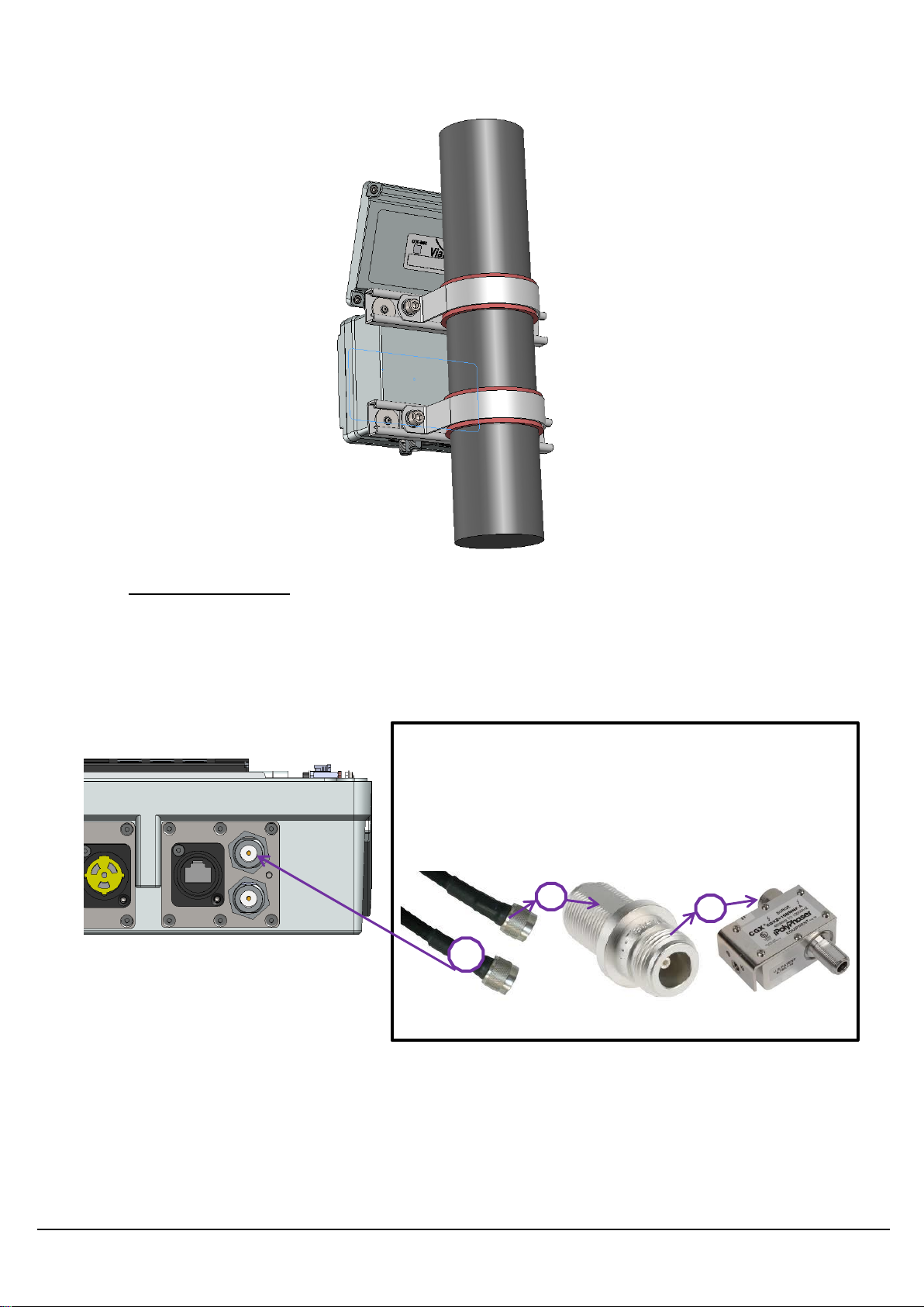
2.4 Lightning Suppressor
There are a number of options available to protect your enclosure and equipment from electromagnetic
pulses. Each suppressor will protect a single RF channel. The larger 70006 suppressor has a grounding
fixing (M8) on the suppressor, this should be used to achieve maximum protection. The standard options are:
27520
Lightning Suppressor Kit for Outdoor Enclosure, 1 required per RF Channel
When fitting a lightning suppressor, first fit the 0.5 m cable
to the N-Type on the ODE-MINI.
Fit the N-Type adaptor to the cable. Then fit the lightning
suppressor to the adaptor on the cable.
Lightning Suppressors
2
3
73951
50035
51645
1
2
3

OUTDOOR ENCLOSURE TYPE MINI HANDBOOK
11
2.5 Antennas
A range of GPS antennas are available that are compatible with the ODE-MINI. A selection are shown below.
70005 GPS marine active antenna, 5 dBi plus 28 dB amplifier.
70040 GPS active antenna, 3.5 dBi plus 50 dB amplifier.
2.6 Termination of RF Connections
The main enclosure terminates the RF input/output via N-Type female connections located on its baseplate.
N-Type connectors are available in both 50 and 75 ohm variants. 50 ohm N-Types are used in the majority of
applications, though if 75 ohm connectors are fitted, you MUST ensure that both halves are the same
impedance; mating dissimilar connectors will cause permanent physical damage.
RF inputs and outputs should not be exposed to DC voltage levels in excess of ±36 V.
Absolute maximum no damage RF input level is nominally +13 dBm
(some units may tolerate more power, please see module handbook).
Some transmitter modules are pre-configured to have a DC voltage present on the RF input connector to
power low noise amplifiers and similar equipment. All receiver modules will create up to 2 V peak DC
transient from the RF output at start up into a 50Ω load (approximately 5 V into a 1 MΩ load). This may cause
failure in some very sensitive equipment.
70005, 33 dBi
Gain antenna
70040, 53.5 dBi
Gain antenna

OUTDOOR ENCLOSURE TYPE MINI HANDBOOK
12
All modules that have AC coupled inputs and/or outputs will be sensitive to large transients (>5V) applied to
either input or output. This may result in permanent damage to the units, particularly to low frequency units.
Some receiver modules are equipped with DC loads on their outputs; please see the module handbook.
Contact ViaLite Communications for more details.
OUTDOOR ENCLOSURE TYPE MINI HANDBOOK
13
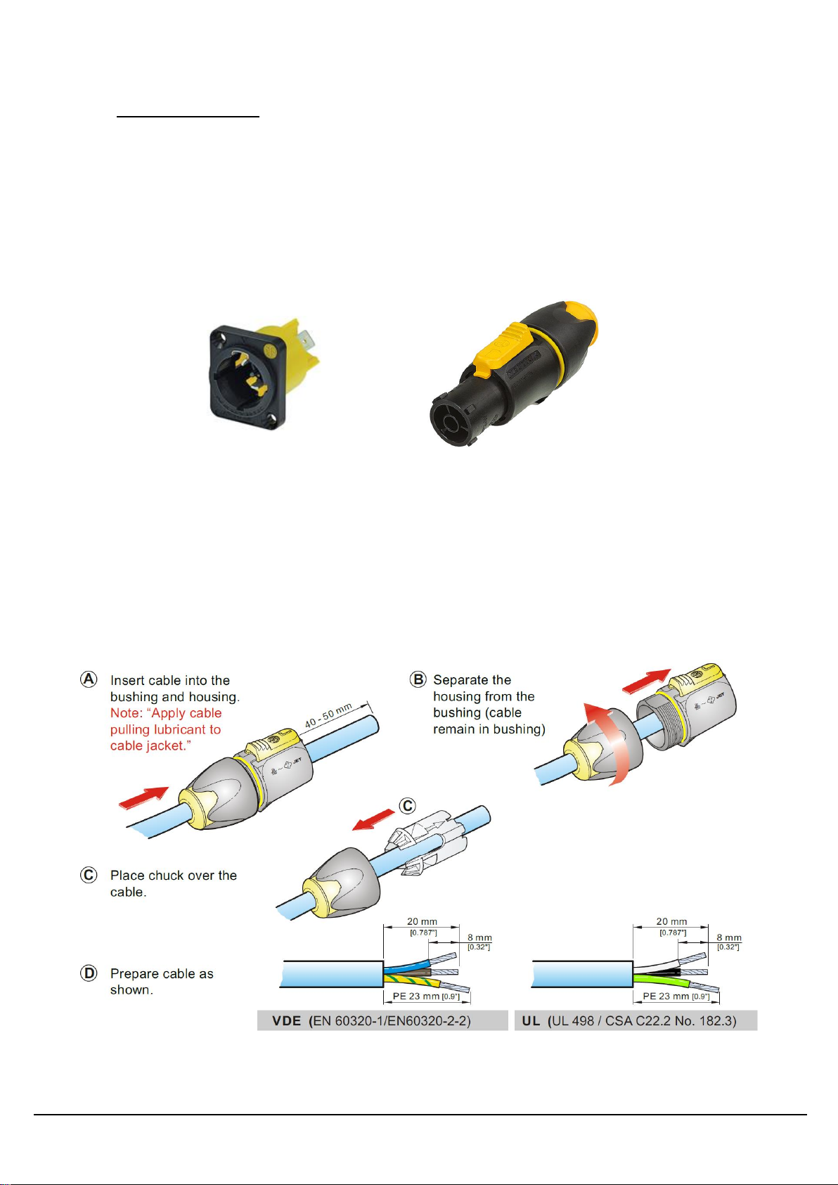
2.7 Termination of power
The ODE-MINI enclosure receives power via a NEUTRIK NAC3 power connector. The male connector is
fitted to the left hand gland plate and the cable mounting free female is supplied for on-site termination.
These are used for both AC and DC power. For AC connection connect LIVE/NEUTRAL/EARTH as labelled.
When used for DC power the POSITIVE should be connected to the LIVE and the NEGATIVE should be
connected to the NEUTRAL. The supplied mating half is:
NAC3FX-W
Female Black, Yellow 2P+E Power Connector Mains 20A Socket Cable Mount, 250 V ac
Polyamide.
This equipment must be earthed in accordance with the local codes. Incomplete or incorrect earthing will
cause a safety hazard. The incoming power cable must have a diameter between 6 and 12 mm to be correctly
retained by the connector. The electrical conductor cross sectional area should be within the range of 1 - 2.5
mm2to ensure sufficient current handling of up to 2 Amps. This equipment is not intended for direct
connection to building installation wiring; ensure connection is via an overcurrent protection breaker and/or
residual current device.
Ensure that the power cable is isolated and no power is present during installation.
Follow the steps below to fit the power connector

OUTDOOR ENCLOSURE TYPE MINI HANDBOOK
14
2.8 Termination of Optical fibre
The optical fibre can be terminated in the following optional patch box (5488X). As standard, the patch cable
presents SC/APC connections to the end user within the patch box as shown in the picture below. Options to
terminate in LC/APC or FC/APC are available.
A kit of additional parts and adapters is supplied with the patch box to allow the customer to tailor their
installation on site.
A
B
1 (a)
2 (b)
QUAD IDENTS
A –Module 2
B –Module 1
a –SFP 1
b –SFP 2
Feed from ODE-MINI
Feed from external site
OUTDOOR ENCLOSURE TYPE MINI HANDBOOK
15
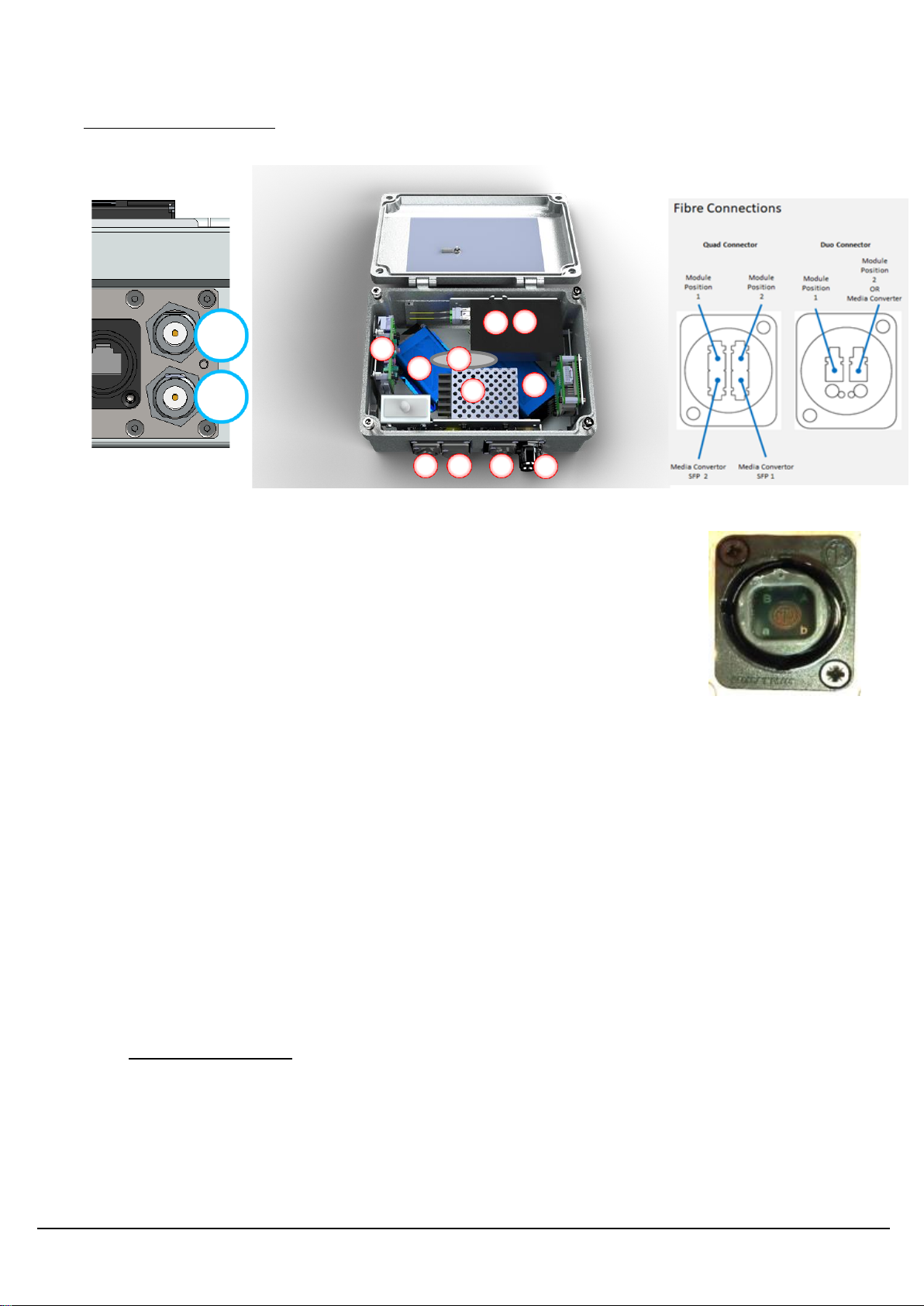
ODE-MINI, internal features
The internals of the ODE-MINI are presented as follows:
The top section houses the dual power supplies which sit directly above the power distribution bar. Within this
bar are the power sharing electronics to support the redundant power supply feature and the LNB voltage
generator. LEDs indicating the presence and state of each PSU module are presented to aid both installation
and diagnostic processes. A replaceable fuse is present also.
The main module bay, supports up to 2 ViaLiteHD blue or yellow modules or a single purple module.
Standard layout is TX in slot 1 and RX in slot 2. Item 5 in the list above - Module 1 - is usually TX, and item 6
- Module 2 –is usually RX.
Connect RJ45 and interrogate the site controller to confirm part numbers, serial numbers and settings (gain
etc.).
If using a standard ODE-MINI at both ends of the link, you must ensure your Neutrik cable is a crossover, with
the module ports 1 and 2 crossed over and the SFP ports 1 and 2 crossed over.
2.9 LNB Voltage selection
ViaLiteHD Blue modules have the option to pass a voltage via the internal bias T to any connected RF
equipment (e.g. LNBs).
There are options for (NONE), (Fixed 12V), (Fixed 48V) and customer variable (13V, 15V, 18V or 24V) as
illustrated below.
1
2
3
4
5
6
7
8
9
1) Primary PSU
2) Media Converter
3) Secondary PSU Position
4) LNB Voltage Selector
5) Module 1
6) Module 2
7) RF Connection(s)
8) Optical connector
9) Power Connector
10) Fuse
11) Management RJ45 port
10
11
P1
P2
INTERNAL CONNECTION VIEW
FIBRE TYPE: LC/APC ONLY
REAR VIEW SHOWN BELOW
FIBRE CONNECTOR FRONT
VIEW SHOWN BELOW

OUTDOOR ENCLOSURE TYPE MINI HANDBOOK
16
An option for 13V output is also available. This can be partnered with the customer selectable voltage (usually
18 V) to power LNBs with voltage defining polarisation switching. The user can then operate two optical links,
one serving each polarisation from a dual LNB.
LNB Customer variable voltage source
The ODE-MINI incorporates an optional, selectable voltage power supply to facilitate antenna LNB powering if
required.
The user must ensure that the power requirements of their LNB(s) do not exceed the ODE-MINI power
capacity which is labelled internally. To drive external equipment with very high power requirements (e.g. a
BUC) the option for dual redundant power supplies can be substituted for a dedicated supply to provide this
function which bypasses this selector. See next section (ODE-MINI power supplies) for details.
The ODE-MINI LNB voltage setting is factory set to match the customer requirement prior to shipping, but
should it need changing, the following procedure should be performed:
Power down the enclosure by switching both power supplies off.
Using a 2.5 mm flat blade screwdriver or small crosshead, adjust the 4 position switch such that its arrow
head is pointing toward the desired voltage.
Re-establish power by switching on the power supply switches.
13V
V
15V
V
24V
V
18V
V

OUTDOOR ENCLOSURE TYPE MINI HANDBOOK
17
LNB Voltage tolerance
The LNB voltage presented at the RF ports is nominally per the setting, but manufacturing variances have the
potential for the following.
LNB Voltage
setting
Minimum
Maximum
13
12.6
13.5
15
14.6
15.6
18
17.5
18.8
24
23.3
25.0
WARNING: When connecting any equipment to the RF ports that isn’t capable of handling the
LNB voltage, ensure a DC block is used to protect it.
2.10 High voltage or high power LNB/BUC supply options
When the on-board variable supply is not suitable for an application, the option for using a dedicated PSU can
be considered.
Power supply redundancy for the ODE-MINI is then no longer possible, but the option for 12V or 48V at up to
15 W is possible or even 25 W for temperature environments < 45 Degrees Centigrade.
Please consult with the factory for this arrangement as it will be built to order and there are no customer re-
configurable options.
2.11 ODE-MINI power supplies
The ODE-MINI is equipped with internal power supply modules. They are generally used in a dual redundant
configuration with identical modules in the left hand (LH) and right hand (RH) positions. It can optionally be
equipped with either just a single main PSU module (LH) or with a main PSU (LH) and LNA/BUC PSU (RH).
The voltage inputs for the various power supplies’options have the following requirements.
AC input wide range 88 –264 VAC 47-63 Hz Power supply: LPS-MINI
DC input 18-75 VDC Power supply: LPS-MINI-DC
2.12 Replacement of Power Supply Modules
The outdoor housing can be fitted with either one or two power supply modules, the latter provides dual
redundant power supply protection for the housing. The power supplies come pre-installed in the outdoor
housing. Should it be necessary to replace a power supply module, the procedure is as follows:
First isolate the unit from the mains power inlet by switching the power isolation switch adjacent to the
unit OFF.
Disconnect the electrical connections between the power supply module and the switch bar.
Undo the two nuts holding the power supply unit in place. Retain the nuts to refit the new power supply.
Locate the new module on the studs on the rear plate. Replace the nuts to hold the power supply
module in place.
Reconnect the electrical connector between the power supply module and the switch bar.
Apply power by switching the power isolation switch ON.

OUTDOOR ENCLOSURE TYPE MINI HANDBOOK
18
2.13 ODE-MINI replaceable fuse
The incoming power to the ODE-MINI is protected by a common replaceable fuse. This is fitted in-line on the
live cable inside the ODE-MINI. Details of this fuse - if different to the standard fuse - are given in your
custom handbook. The standard fuse is used in all AC, 48 Vdc and 24 Vdc powered units, unless otherwise
advised.
To replace the fuse, the procedure is as follows:
First isolate the unit from the mains power inlet by unplugging the mains power lead.
Unscrew the fuse holder by hand.
Remove the failed fuse from the fuse holder and replace with your new fuse.
Screw the fuse holder back together.
Apply power by switching the power isolation switches ON.
Standard replaceable fuse
1 A, 250 V, anti-surge, 20 x 5mm, PPM part number 57117, please check
before replacing.

OUTDOOR ENCLOSURE TYPE MINI HANDBOOK
19
3 Product warranty
The guarantee / warranty period, unless otherwise agreed in writing, shall be as stated in document F292 -
PPM Manufactured Product –Warranty, which is available at: https://ppm.co.uk/warranty-periods/. Extended
warranty options are available at the time of purchase.
Prior to returning any goods for warranty or non-warranty repairs please contact PPM / ViaLite
Communications for a returns reference.

OUTDOOR ENCLOSURE TYPE MINI HANDBOOK
20
4 FCC Approval
Information to the user of ViaLite products:
For a Class A digital device or peripheral, the following instructions are furnished to the user. This equipment
has been tested and found to comply with the limits for a Class A digital device, pursuant to part 15 of the
FCC Rules. These limits are designed to provide reasonable protection against harmful interference when the
equipment is operated in a commercial environment. This equipment generates, uses, and can radiate radio
frequency energy and, if not installed and used in accordance with the instruction manual, may cause harmful
interference to radio communications. Operation of this equipment in a residential area is likely to cause
harmful interference in which case the user will be required to correct the interference at his own expense.
PULSE POWER &MEASUREMENT LTD 2020.
NO PART OF THIS DOCUMENT MAY BE REPRODUCED OR TRANSMITTED IN ANY FORM WITHOUT PRIOR WRITTEN PERMISSION.
PULSE POWER &MEASUREMENT LTD (PPM), 65 SHRIVENHAM HUNDRED BUSINESS PARK,SWINDON,SN6 8TY, UK.
TEL:+44 1793 784389 FAX:+44 1793 784391
EMAIL :SALES@VIALITE.COM WEBSITE :WWW.VIALITE.COM
This manual suits for next models
1
Table of contents
Other PPM Enclosure manuals


