PPM ViaLiteHD HEA-xx-HB-4 series User manual

HEA-XX-HB-4 VIALITEHD SATCOM6 HANDBOOK
ViaLiteHD
SATCOM6
Outdoor enclosure
User Manual
HEA-xx-HB-4
CR3974 21/12/18
Pulse Power & Measurement Ltd, 65 Shrivenham Hundred Business Park, Watchfield, Swindon, Wiltshire SN68TY, UK
Tel +44 (0)1793 784389 Fax +44 (0)1793 784391 Email sales@vialite.com Web www.vialite.com
HEA-XX-HB-4 VIALITEHD SATCOM6 HANDBOOK
2
Instrument Care and Safety Information
Please read the whole of this section before using your ViaLiteHD product. It contains important safety
information and will enable you to get the most from your Fibre Optic link.
Electrical Safety The ViaLiteHD SATCOM6 enclosure provides the termination for power inputs and can be fitted with power
supplies.
The ViaLiteHD SATCOM6 enclosure is a Safety Class 1 product (having metal chassis directly connected to
earth via the power supply cable).
When operating the equipment note the following precautions:
Hazardous voltages exist within the equipment.
The enclosure earth stud SHOULD be connected to the safety earth.
When using a 2 pin power supply cable the enclosure earth stud MUST be connected to the safety earth.
PSU modules are fused on the mains live feed only. A second fuse should be used for the neutral
connection where the polarity of the connectors can be reversed.
ESD Precautions
Precautions for handling electro-static sensitive devices should be observed when handling all ViaLiteHD
modules. Technicians should ensure that they use effective personal grounding (i.e. ESD wrist strap etc.) when
servicing the equipment. Any equipment or tools used should be grounded to prevent static charge build-up.
Good practice should be observed at all times. For reference see relevant standards.
EN 61340-5-1, “Protection of Electronic Devices from Electrostatic Phenomena – General Requirements”
Optical Safety The ViaLiteHD SATCOM6 enclosure may be fitted with optical units
The ViaLiteHD RF Transmitter and Transceiver modules contain laser diode sources operating at nominal
wavelengths of 1270nm to 1610nm.
These devices are rated as EN60825-1:2007 CLASS 1 radiation emitting devices. A class 1 laser is safe
under all conditions of normal use.
When operating the equipment note the following precautions:
Never look into the end of an optical fibre directly or by reflection either with the naked eye or through an
optical instrument.
Never leave equipment with radiating bare fibres –always cap the connectors.
Do not remove equipment external covers when operating.
Hot surface When operated under full load and elevated temperature the SATCOM6 enclosure can become hot.
Suitable precaution should be taken when handling this device.
Allow to cool for 10 minutes
Do not touch metallic surfaces or printed circuit board when hot.

HEA-XX-HB-4 VIALITEHD SATCOM6 HANDBOOK
3
TABLE OF CONTENTS
1INITIAL INSPECTION........................................................................................................................................................4
2INTRODUCTION TO THE VIALITEHD RANGE .................................................................................................................4
3SATCOM6 SYSTEM DESCRIPTION.................................................................................................................................5
3.1 Backplane connections..........................................................................................................................................7
3.2 Glandplate connections .........................................................................................................................................9
3.3 External interface connectors and fuses...............................................................................................................10
3.4 Power system......................................................................................................................................................10
3.4.1 Power supplies........................................................................................................................................10
3.4.2 Power Requirements...............................................................................................................................10
3.4.3 Power supply specification ......................................................................................................................11
3.4.4 Thermal load...........................................................................................................................................11
4ENCLOSURE INSTALLATION.........................................................................................................................................12
4.1 Cold weather option.............................................................................................................................................12
4.2 Cabinet climate option .........................................................................................................................................12
5SYSTEM CONFIGURATION............................................................................................................................................13
5.1 Slots configuration...............................................................................................................................................13
5.2 Summary alarm configuration ..............................................................................................................................14
5.3 SNMP card configuration.....................................................................................................................................14
5.4 Fan operation.......................................................................................................................................................14
5.5 External D25 connector .......................................................................................................................................15
5.6 Using LNBs..........................................................................................................................................................15
5.6.1 Internal LNBs (up to two LNB power cards may be fitted to the SATCOM6) ............................................15
5.6.2 External LNB, power routed via mother board.........................................................................................15
5.6.3 External LNB/BUC, using bias tee modules.............................................................................................15
5.7 Module Interface ratings.......................................................................................................................................15
5.7.1 Logic interface, TTL 5V ...........................................................................................................................15
5.7.2 Logic interface, RS232............................................................................................................................16
5.7.3 Logic interface, RS422/485 .....................................................................................................................16
5.7.4 Logic interface, I2C..................................................................................................................................16
5.7.5 Logic interface, Open Drain, output .........................................................................................................16
5.7.6 Power interface, +12V, input....................................................................................................................16
5.7.7 Relay contacts.........................................................................................................................................16
5.7.8 Cabinet power input, AC..........................................................................................................................16
5.7.9 Cabinet power input, 12VDC...................................................................................................................16
5.7.10 Cabinet power input, 24VDC...................................................................................................................17
5.7.11 Cabinet power input, 48VDC...................................................................................................................17
6ADDITIONAL AUXILIARY MODULES..............................................................................................................................18
6.1 70029 High current Bias Tee, 50 ohms................................................................................................................18
6.2 70030 High current Bias T DC, 75 ohms..............................................................................................................19
6.3 70042 Low current Bias T DC Injector, 50 ohms..................................................................................................19
6.4 70021 Low current Bias T DC Injector, 50 ohms..................................................................................................20
6.5 56097 RF splitter/combiner, 2 way, 10-2500MHz, 50 ohms .................................................................................20
6.6 56098 RF splitter/combiner, 2 way, 10-2500Mhz, 75 ohms..................................................................................21
6.7 56100 RF splitter/combiner 3 way, 700-2400MHz, 50 ohms ................................................................................21
6.8 56140 RF splitter/combiner 4 way, 400-2400MHz, 50 ohms ................................................................................22
6.9 56088 Diplexer and Bias Tee, 4 port, 10MHz + L-Band + DC, 50 ohms...............................................................22
6.10 56089 Diplexer and Bias Tee, 3 port, 10MHz + L-Band + DC, 50 ohms...............................................................23
6.11 53236 CWDM 4 channel module, wave length 1550nm, 1570nm, 1590nm, 1610nm ...........................................23
6.12 53237 CWDM 8 channel high isolation module, wave length 1470 - 1610nm.......................................................24
6.13 53238 CWDM 8 channel standard isolation module, wave length 1470 - 1610nm................................................24
6.14 54150 Ancillary Ethernet module .........................................................................................................................25
6.15 56213 RF splitter/combiner 6 way, 10-200MHz, 50 ohms ....................................................................................25
6.16 56214 RF splitter/combiner 3 way, 5-500MHz, 50 ohms ......................................................................................26
6.17 92223 Tray fusion splice holder ...........................................................................................................................26
7SATCOM6 SPECIFICATION............................................................................................................................................27
8SATCOM6 PART NUMBER MATRIX...............................................................................................................................28

HEA-XX-HB-4 VIALITEHD SATCOM6 HANDBOOK
4
1 Initial Inspection
Unpack and inspect the equipment as soon as possible. If there is any sign of damage or any parts missing, do not install the
equipment before seeking advice from PPM or your local agent.
The equipment received should match the delivery note that is shipped with the equipment. Contact ViaLite Communications or
your local agent in case of any discrepancies.
2 Introduction to the ViaLiteHD Range
The ViaLiteHD range has been developed to provide a modular solution to the transmission of a wide range of analogue and digital
data where traditional ‘copper wire’ systems cannot be used, for example, in electrically noisy environments or over long distances.
The range is ideal for permanent and semi-permanent installation in Satellite communications, GPS, antenna remoting and other
related applications.
The variety of links available includes low frequency timing (2kHz) to wideband RF (4.2GHz), RF splitters, Oscillators, Amplifiers and
Protection switches; they also include a full suite of supporting functions including RS232/422/485, Ethernet (to 1000 BT) and control
systems to monitor and control the system with both Web and SNMP interfaces.
All ViaLiteHD equipment operates over high quality glass fibre optic cable, which can be supplied in low-cost 3mm jacket, riser and
outdoor specifications. The links can also be used with existing cable systems at customer premises.
A ViaLiteHD system can be added to at any time, enabling the system to evolve with the needs of the user.
ViaLiteHD is a product brand manufactured by Pulse Power and Measurement Ltd (PPM). ViaLite Communications is a division of
Pulse Power and Measurement Ltd (PPM).
HEA-XX-HB-4 VIALITEHD SATCOM6 HANDBOOK
5
3 SATCOM6 System Description
The SATCOM6 is a stainless steel, weatherproof enclosure designed specifically to be mounted near or by the antenna at teleports
and ground stations. The enclosure accepts up to six ViaLiteHD modules including all RF, digital and ancillary modules. The
enclosure can be fitted with dual power supplies, switch and splitter modules to enable full redundancy. The electrical and optical
interfaces are highly configurable. There is also space in the cabinet for ancillary components such as a multi-way splitter, duplexer,
high power bias-tees, fibre dressing and a fibre splice tray. The motherboard offers optional LNA/LNB power routing as well as
13/18/22V and 22kHz tone.
Key features:
Wall or pole mount
Dual power supplies
Integrated SNMP for remote monitor and control
LNB powering
Built in Ethernet switch (option with SNMP card)
The mainboard accepts up to six ViaLiteHD modules. Additionally two LNB units can be populated to the rear side of the
motherboard. Standard RX/TX ViaLiteHD modules units can be placed in any of the six slots, some ancillary ViaLiteHD modules
offer full functionality only if placed in particular slots.
Slot number
1
2
3
4
5
6
7
8
9
10
11
Connector reference
J12
J13
J14
J15
J16
J17
J18
J19
J25
J7
J8
Module Type
RF standard
x
x
x
x
x
x
RF + digital
x
x
RF - High power
x
x
x
x
x
x
Amplifier
x
x
x
x
x
x
Splitter
x
x
Switch
x
x
Serial Digital
x
x
Ethernet
x
x
x
x
x
x
PSU - LNB (13/18V)
x
x
SNMP
x
Summary Alarm
x
PSU main (12V)
x
PSU reserve (12V)
x
PSU LNA (3.3-48V)
x
Table 1 Motherboard slots population matrix

HEA-XX-HB-4 VIALITEHD SATCOM6 HANDBOOK
6
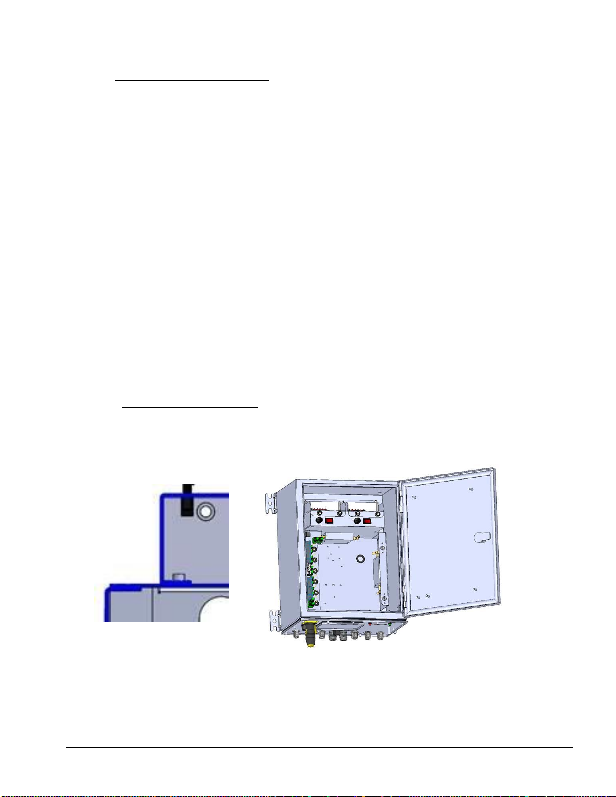
Figure 1 SATCOM6 enclosure, illustrated are several EDGE modules mounted to the Backplane PCB
Optional sunshield
Optical adapters
Fans
SNMP card
craft port
Backplane
LNBs
PSUs
Mounting hinges
Power switches
SNMP Management
& Control PCB
HEA-XX-HB-4 VIALITEHD SATCOM6 HANDBOOK
7
3.1 Backplane connections
Your cabinet should be delivered fully configured as per your order, and ready to operate. The details of the default backplane
configuration will be contained in your order specific handbook that your SATCOM6 is delivered with.
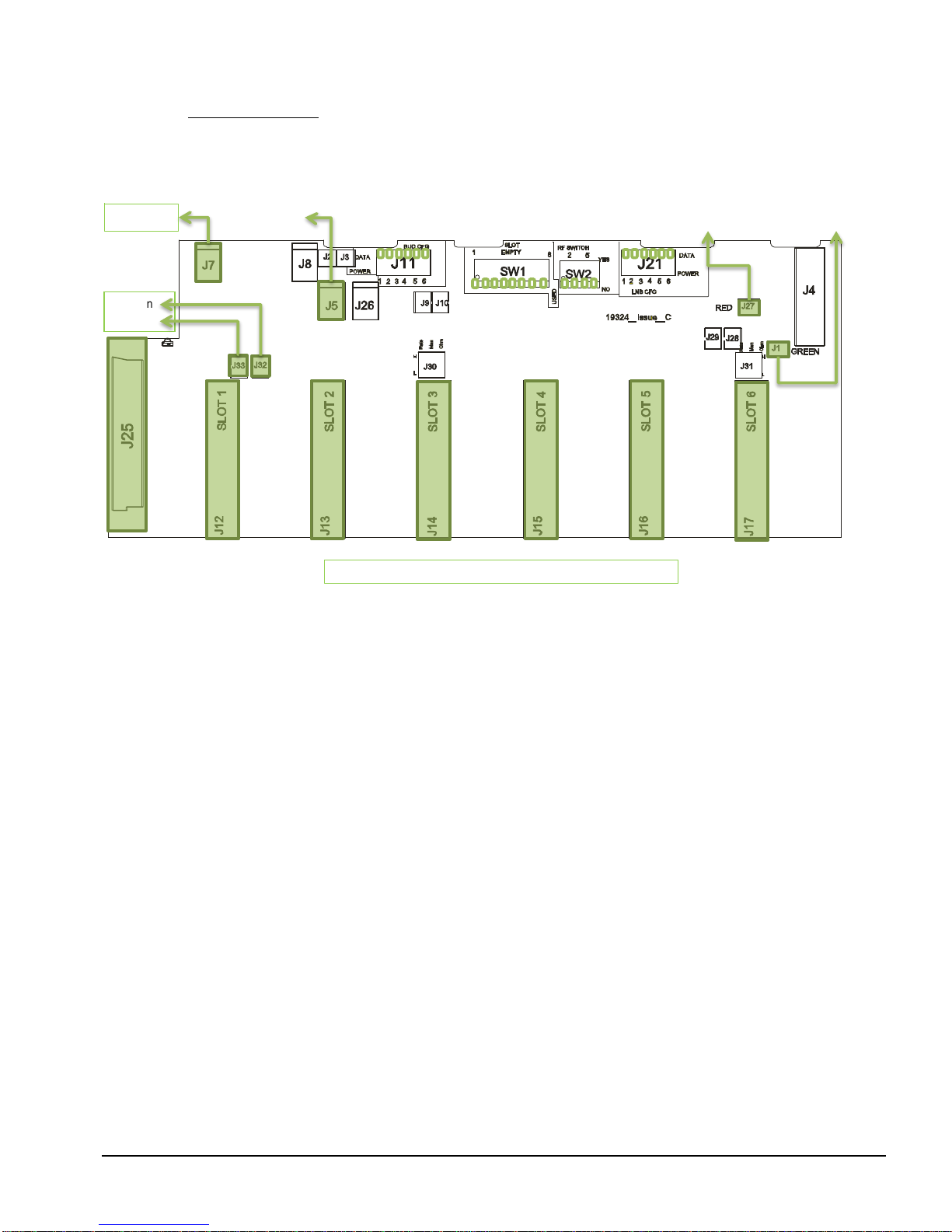
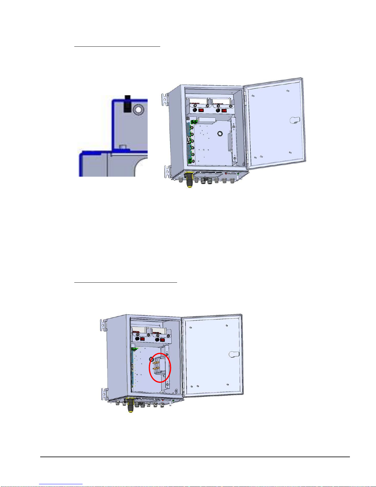
Figure 2 Location of switch and jumpers on the backplane
D6–fan
status
PSU Main
Note that J18 and J19 are located on the other side of the board
HEA-XX-HB-4 VIALITEHD SATCOM6 HANDBOOK
8
Switch/
jumper
Function description
Configuration example
Configuration example description
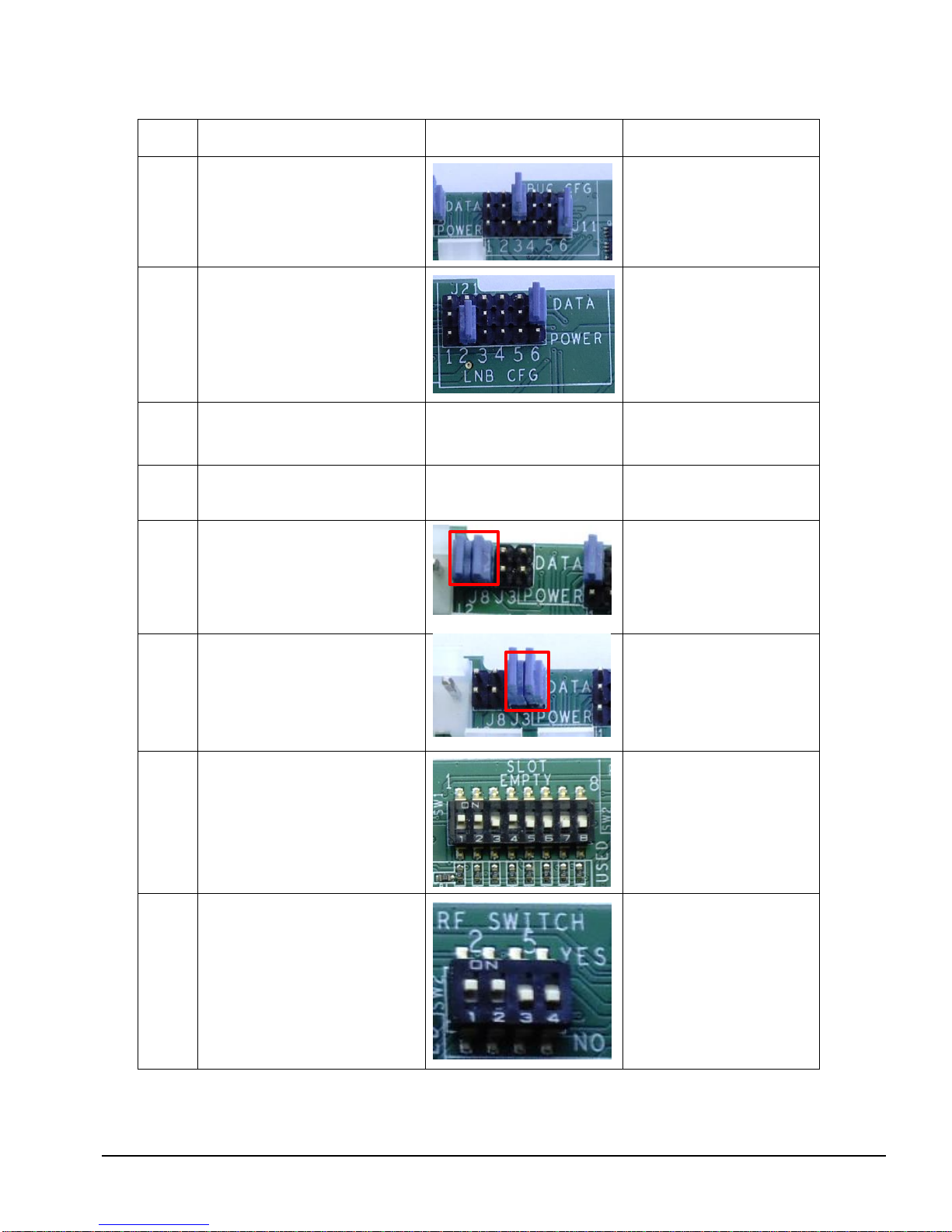
J11
‘POWER’ (jumper down) connects the
output of the LNB to the BUC FEED pin
of the fibre optic receiver; ‘DATA’
(jumper up) allows using serial interface.
Serial digital card used in
SLOT3
LNB2 supplied to pin 1 (BUC
feed) of SLOT6
J21
‘POWER’ (jumper down) connects the
output of the LNB to the LNB FEED pin
of the fibre optic transmitter; ‘DATA’
(jumper up) allows using serial interface.
Serial digital card used in
SLOT6
LNB1 supplied to pin 1 (LNB
feed) of SLOT2
J30
Used to specially configure the serial
digital module in SLOT 3 (refer to HRS-
HB-6 SUPPORT MODULE HANDBOOK
Section 3.4).
If used this would normally be
connected to special interface
cable.
J31
Used to specially configure the serial
digital module in SLOT 6 (refer to HRS-
HB-6 SUPPORT MODULE HANDBOOK
Section 3.4).
If used this would normally be
connected to special interface
cable.
J2
Connects the output of LNB1 (SLOT7) to
the external voltage feed (J5 & J26). J2
is highlighted in red.
J2 is the 4 pin connector next to J8
LNB1 connected to J5 & J26
These jumpers are electrically in
parallel, both should be fitted.
J3
Connects the output of LNB2 (SLOT8) to
the external voltage feed (J5 & J26). J3
is highlighted in red.
LNB2 connected to J5 & J26
These jumpers are electrically in
parallel, both should be fitted.
SW1
‘EMPTY ’position masks the alarms from
unused modules. ‘USED’ should be set if
the slot is occupied.
Slots 1, 2 and 4 set as empty
Slots 3, 5, 6, 7 and 8 set as
used
Alarm lines from slots 1, 2 and 4
will be ignored.
SW2
Connects the alarm lines from adjacent
slots to the RF switch. ‘ON’ if RF switch
is populated in the slot, ‘OFF’ otherwise.
DIP switch 1 + 2
SLOT2 used for the switch
module, ON
SLOT2 used for general
purpose, OFF
DIP switch 3 + 4
SLOT5 used for the switch
module, ON
SLOT5 used for general
purpose, OFF
Table 2 List of jumpers and switches on the backplane
HEA-XX-HB-4 VIALITEHD SATCOM6 HANDBOOK
9
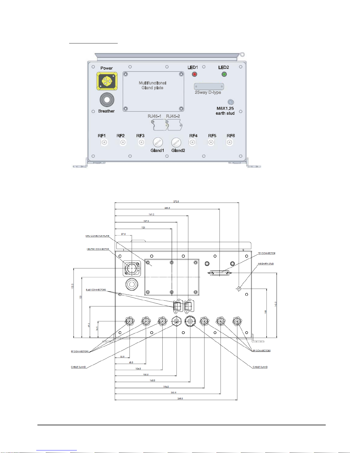
3.2 Glandplate connections
Figure 3 SATCOM6 enclosure - bottom view
Any unused connections will be environmentally sealed.
Figure 4 SATCOM6 glandplate with dimensions

HEA-XX-HB-4 VIALITEHD SATCOM6 HANDBOOK
10
3.3 External interface connectors and fuses
RF connector: N-Type female, impedance to match your RF modules
Power connector:* Circular plug [Neutrik Powercon True1]
Gland: M16 Gland accommodate wire diameters 2 to 7mm [Lapp Kabel 53112110]
* If no power cable is supplied a mating half will be supplied unwired, with assembly instructions
A range of preterminated power cables are available contact ViaLite Communications for more details.
55036 Connector, Neutrik Powercon, Mains, 16A, Female, Cable mounting, spare
73922 Mains Lead, Neutrik extension cable, 1.5m, Neutrik Powercon, male to female
93426 Mains Lead, UK 3 pin plug to Neutrik Powercon, 2m long,
93427 Mains Lead, UK 3 pin plug to Neutrik Powercon, 3m long,
93428 Mains Lead, Neutrik Powercon to 16A Commando plug, 3m long
Figure 5 Neutrik Powercon True1, power connector
3.4 Power system
The SATCOM6 can be fitted with up to two power supplies, this consists of either one or two main power supplies and up to one LNA
power supply; dependent on the required configuration, see section 3, Table 1. If two main power supplies are fitted they will run as
main and redundant. The main and redundant power supplies are OR’d by high efficiency MOSFET switches, only one actively
supplies current, changeover between power supplies is automatic. The configuration of your system will be detailed in the order
specific handbook that your SATCOM6 is delivered with.
3.4.1 Power supplies
Power supplies can be fitted as either main power supplies or LNA power supplies. The main power supplies available are:
HPS-6 Mains Power Supply, 90-264VAC i/p, 50W, +12V output
HPS-7 DC Power Supply, 9.2-18VDC i/p, 25W, +12V output
HPS-8 DC Power Supply, 19-36VDC i/p, 25W, +12V output
HPS-9 DC Power Supply, 36-72VDC i/p, 25W, +12V output
The LNA power supply can be used to provide power directly to a connected LNA or BUC, either via the fitted EDGE transmitter
modules or via bias tee modules fitted within the enclosure. LNA power supply modules available are:
HPS-6 Mains Power Supply, 90-264VAC i/p, 50W, +12V output
HPS-6-15 Mains Power Supply, 90-264VAC i/p, 50W, +15V output
HPS-6-24 Mains Power Supply, 90-264VAC i/p, 50W, +24V output
HPS-6-48 Mains Power Supply, 90-264VAC i/p, 50W, +48V output
HPS-7 DC Power Supply, 9.2-18VDC i/p, 25W, +12V output
HPS-7-24 DC Power Supply, 9.2-18VDC i/p, 25W, +24V output
HPS-8 DC Power Supply, 19-36VDC i/p, 25W, +12V output
HPS-8-24 DC Power Supply, 19-36VDC i/p, 25W, +24V output
HPS-9 DC Power Supply, 36-72VDC i/p, 25W, +12V output
HPS-9-24 DC Power Supply, 36-72VDC i/p, 25W, +24V output
Note: Power supply output voltage can be trimmed to match specific applications, other options are also available. Contact ViaLite
Communications for more details.
3.4.2 Power Requirements
Ensure that the power supplies fitted in your system are sufficient to power the complete system. The power supplies are designed to
operate in dual redundancy, without current sharing. Hence power capability of one supply must be sufficient to power the complete
chassis.
The details below maybe used to approximate the power output requirements from the main power supplies.
EDGE Transmitter 2.0 W typical per slot, excluding LNA/LNB power
EDGE DWDM Transmitter 3.2 W / 4.0W / 6.0 typical per slot at 25/50/60°C
EDGE Receiver 1.5 W typical
EDGE Amplifier 2.4W typical
EDGE Serial Digital 0.7W typical
Fix wires to appropriate
screw terminals

HEA-XX-HB-4 VIALITEHD SATCOM6 HANDBOOK
11
EDGE Switch 0.4W typical
EDGE Splitter 0.4W typical
EDGE Ethernet 1.9W typical
SNMP controller 4.0 W typical
EDGE LNB PSU 7.1W typical (@ output 18V, 350mA)
EDGE LNB PSU efficiency 88% typical, for HRP-1-00-0N-00
AC to DC efficiency 84.5% typical, for HPS-6, more details see section 3.4.3
DC to DC efficiency 75% typical, for HPS-7/8/9, more details see section 3.4.3
The input power requirements can be calculated by using the power supply efficiency below.
3.4.3 Power supply specification
HPS-6
HPS-7/8/9
Description
Wide input range AC power supply
Wide input range DC power supply
Dimensions, external (W x H x D)
153 x 101 x 53 mm
Weight
0.5kg
Input Supply Power
110VAC or 230VAC nominal at 50/60Hz
88 - 264VAC absolute range at 47/63Hz
HPS-7 9.2-18VDC
HPS-8 19-36VDC
HPS-9 36-72VDC
Efficiency, typical
HPS-6 84.5%
HPS-6-15 86%
HPS-6-24 88%
HPS-6-48 89%
HPS-7 72%
HPS-7-24 75%
HPS-8 75%
HPS-8-24 78%
HPS-9 78%
HPS-9-24 81%
Switch on current
<33A @ 230Vac
<10A
Output voltage
HPS-6 12V +/- 0.5V
HPS-6-15 15V +/- 0.5V
HPS-6-24 24V +/- 1.0V
HPS-6-48 24V +/- 1.0V
HPS-7 12V +/- 0.5V
HPS-7-24 24V +/- 1.0V
HPS-8 12V +/- 0.5V
HPS-8-24 24V +/- 1.0V
HPS-9 12V +/- 0.5V
HPS-9-24 24V +/- 1.0V
Output ripple
120mV for output voltages 12V and 15V, 200mV for output voltages of 24V and 48V
Maximum input current
1.3A at 115VAC
0.8A at 230VAC
HPS-7 3.2A at 12VDC
HPS-8 1.6A at 24VDC
HPS-9 0.8A at 48VDC
Maximum output power at +50C
50 W
25 W
Minimum load power
No minimum load current
Derating >+50C
2.0% / C, absolute maximum 70C
2% / C, absolute maximum 60C
Hot-swapping
Yes, using cabinet hardware
Dual Redundant
Yes, with appropriate cabinet configuration
Output current overload
Switches output OFF and automatically restarts at 125% nominal current
Output over voltage
Switches output OFF and automatically restarts at 125% nominal voltage
Status Indicators
GREEN power LED
MTBF @25C
228 000 hours
365 000 hours
3.4.4 Thermal load
The SATCOM6 is design to work with a “full configuration thermal load”across the full specified operating temperature range.
A full thermal load consist of
6 EDGE Transmitters
2 EDGE LNB power supplies (250mA @13V each)
1 SNMP and web controller
2 Main power supplies (HPS-6)
The “full configuration thermal load”is 21 watts typically, this includes and allows for module power dissipation (EDGE TX + SNMP
and web controller), LNB efficiency and main power supply efficiency. Thermal loads in excess of this will affect the maximum
operating temperature. Thermal loads in excess of the “full configuration thermal load” will typically linearly reduce the maximum
operating temperature.
ViaLite Communications will advise the maximum configuration for cabinets fitted with EDGE DWDM transmitters as these have
significantly different thermal characteristics and different thermal interaction with other modules due to their active cooling.
ViaLite Communications will evaluate if your requested build configuration exceeds the “full configuration thermal load”and advise
you of any impact. Any issues will be noted in the order specific handbook that your SATCOM6 is delivered with, contact ViaLite
Communications for more details.
HEA-XX-HB-4 VIALITEHD SATCOM6 HANDBOOK
12
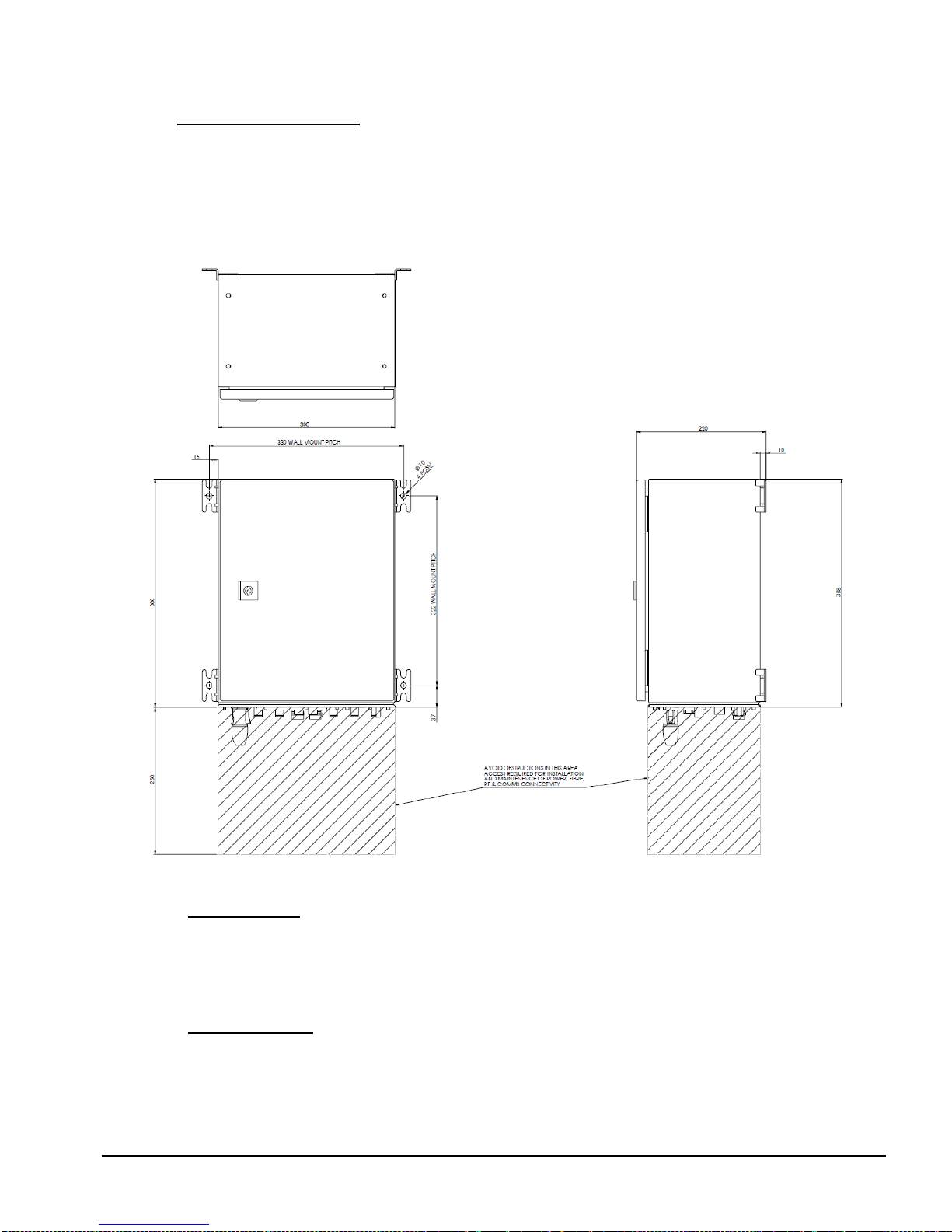
4 Enclosure installation
The SATCOM6 enclosure has been designed to work in harsh environments. The maximum ambient temperature for the enclosure is
+55oC. When installing the enclosure pay attention to the following:
1. Leave open space around the enclosure to allow air circulation (minimum gap of 15cm is recommended).
2. Avoid installation in places with direct exposure to the sun. Consider using the optional sunshield if the unit will be in direct
sunlight. Please contact ViaLite Communications for assistance to identify the correct part if you want to use a sunshield.
3. In the event that both internal cooling fans fail, the maximum ambient temperature that the SATCOM6 can operate in will be
reduced by 10oC, to +45oC.
Figure 6 SATCOM6 wall mounting, including dimensions of fixing centres
4.1 Cold weather option
The SATCOM6 can operate down to -10oC without a heater. If lower temperature operation is required contact ViaLite
Communications, there are several heater options available for the SATCOM6.
Heater mats 76194 and 76197 are fitted with a built in thermal switch which enable thermal output at a temperatures below 10
degrees centigrade. Heater mats 76194 and 76197 are powered by the internal +12V supply.
4.2 Cabinet climate option
70052 SATCOM6 Solar Shield
76194 SATCOM6 enclosure, Heater mat, +12V, 15 Watt, for cold climate
76197 SATCOM6 enclosure, Heater mat, +12V, 6 Watt, for cold climate

HEA-XX-HB-4 VIALITEHD SATCOM6 HANDBOOK
13
5 System configuration
5.1 Slots configuration
Your SATCOM6 should be delivered preconfigured to your order instructions. To check the configuration, please follow the procedure
below.
1. Check if the module is suitable to be used in the slot according to the pin outs it has (see table 1 in section 3).
2. Using jumpers J11 and J21 configure pins 1 and 9 of the slot. Setting the jumper to ‘POWER’ connects the relevant pin to
the output of the LNB card. Setting to ‘DATA’ activates serial data interface (for serial digital modules in slots 3 or 6). If
using LNB power generated from SATCOM6 LNB power cards then slots 1, 2 and 3 are powered by LNB 1 (slot 7), and
slots 4, 5 and 6 are powered by LNB 2 (slot 8).
3. If an RF switch card is fitted to a slot check SW2 is in ‘YES’ position, otherwise place it in the ‘NO’ position.
4. Serial digital cards can only be used in slots 3 and 6. They can be configured via SNMP or manually. To set parameters
manually use jumpers J30/J31. Refer to the ViaLiteHD RF Support Module handbook for more information about
configurable parameters.
5. Check the position of jumpers J2/J3. If jumpers are closed the external LNB is connected.
6. For all populated slots set SW1 switch to ‘USED’ position. If a slot is left empty set the SW1 switch to the ‘EMPTY’ position.
Refer to section 3.1 for detailed description of all jumpers and switches on the motherboard.
The pin-out of the slots can be found in the tables below.
Pin number
Pin description
1
BUC FEED (configurable via J11)
2
NC
3
NC
4
GND
5
VCC
6
NC
7
NC
8
NC
9
LNB FEED (configurable via J21)
10
NC
11
NC
12
ALARM
13
NC
14
SCL
15
SDA
Table 3 Slots 1 and 4 pin-outs
Pin number
Pin description
1
BUC FEED (configurable via J11)
2
NC
3
NC
4
GND
5
VCC
6
NC
7
NC
8
NC
9
LNB FEED (configurable via J21)
10
ALARM LEFT (switchable via SW2)
11
NC
12
ALARM
13
ALARM RIGHT (switchable via SW2)
14
SCL
15
SDA
Table 4 Slots 2 and 5 pin-outs
HEA-XX-HB-4 VIALITEHD SATCOM6 HANDBOOK
14
Pin number
Pin description
1
BUC FEED or TX422 IN+ (configurable via J11)
2
TX422 IN-
3
TX232 IN
4
GND
5
VCC
6
RX422 OUT+
7
RX422 OUT-
8
RX232 OUT
9
LNB FEED or RTS (configurable via J21)
10
Serial CFG1
11
Serial CFG2
12
ALARM
13
Serial CFG3
14
SCL
15
SDA
Table 5 Slots 3 and 6 pin-outs
Pin number
Pin description
1
NC
2
NC
3
NC
4
NC
5
NC
6
NC
7
NC
8
NC
9
LNB FEED output
10
NC
11
NC
12
ALARM
13
NC
14
SCL
15
SDA
Table 6 Slots 7 and 8 pin-outs
5.2 Summary alarm configuration
The SATCOM6 enclosure is equipped with the summary alarm indication by mean of two external LEDs. Green indicates normal
operation, and red indicates an alarm condition in one or more of the slots. No light indicates a power failure. Alarm circuitry is open
drain type, requiring each unit to actively pull down to indicate normal mode of operation. In such circuit topology an empty slot would
raise an alarm. To prevent such a situation DIP switch SW1 should be set according to the configuration, switch to ‘USED’ position if
the slot is occupied ‘EMPTY’ if the slot is unoccupied. The switch allows masking of alarms from any of the 6 main slots or the 2
additional LNB slots.
5.3 SNMP card configuration
SATCOM6 can be monitored and controlled via a web browser or SNMP management system. Before first use the system has to be
configured. Refer to HRC-1 handbook to find more details about the set-up process.
5.4 Fan operation
To allow reliable operation under harsh environmental conditions the SATCOM6 is equipped with two fans enabling internal air
circulation. The speed of the fans is dependent on internal temperature. D6 LED indicates the status of the fans.
D6 LED state
Fan status
Off
Internal temperature below the limit, fans off
Blinking GREEN
Fans working between 40% and 100%
Solid GREEN
Fans working at 100%
RED
Fans’ failure
Table 7 Fan diode status
HEA-XX-HB-4 VIALITEHD SATCOM6 HANDBOOK
15
5.5 External D25 connector
The external D25 connector provides access to serial interface if serial digital cards are installed in slot 3 or 6. Refer to the serial
digital cards handbook for more information. Dry relay contacts to indicate alarms are also available.
Pin
Pin description
Description
Pin
Pin description
Description
1
GND
14
RX 422 OUT- 6
RS422 interface –SLOT6
2
RX 422 OUT+ 3
RS422 interface –SLOT3
15
TX 232 IN 6
RS232 interface –SLOT6
3
TX 422 IN+ 3
RS422 interface –SLOT3
16
RX232 OUT 6
RS232 interface –SLOT6
4
RX 422 OUT- 3
RS422 interface –SLOT3
17
GND
5
TX 422 IN- 3
RS422 interface –SLOT3
18
RTS 6
RTS –SLOT6
6
RX232 OUT 3
RS232 interface –SLOT3
19
RELAY 1
Dry relay contact (NO –normally open)
7
TX 232 IN 3
RS232 interface –SLOT3
20
GND
8
RTS 3
RTS –SLOT3
21
RELAY 2
Dry relay (COM –common)
9
GND
22
VCC
10
GND
23
RELAY 3
Dry relay contact (NC –normally closed)
11
TX 422 IN+ 6
RS422 interface –SLOT6
24
EXT V+
External power +
12
RX 422 OUT+ 6
RS422 interface –SLOT6
25
EXT V-
External power -
13
TX 422 IN- 6
RS422 interface –SLOT6
Table 8 Normal Pin-out of the D25 connector, may differ for some special applications, see cabinet specific handbook
NOTE: Relay contacts are available only if SNMP or SUMMARY ALARM card are fitted.
NOTE: Check jumpers J11 and J21 before connecting D25.
5.6 Using LNBs
5.6.1 Internal LNBs (up to two LNB power cards may be fitted to the SATCOM6)
1. Make sure that J2 and J3 jumpers are not populated.
2. Place the LNB unit in slot 7 or slot 8. Configure the LNB, for details refer to the LNB manual. The LNB card in slot 7
supplies voltage to slots 1-3, and the LNB card in slot 8 supplies voltage to slot 4-6.
3. Using jumpers J11 and J21 connect the LNB to the modules. Use J11 if an optical receiver is used or J21 for a transmitter.
J11 in ‘POWER’ position connects the power from the LNB to the BUC FEED pin of the receiver. J21 connects the power
from LNB to the LNB FEED pin of the transmitter.
5.6.2 External LNB, power routed via mother board
If an external power supply is used instead of LNB units follow this procedure:
1. Connect power to the J5 connector
2. By closing J2 jumper the power is routed to the output of the LNB1 internal module (slot 7). Closing J3 jumper routes the
power to the output of the LNB2 module (slot 8). Before closing one of the jumpers make sure that relevant slots are not
populated.
3. Using jumpers J11 or J21 route the power to the appropriate slots –refer to ‘Internal LNBs’ section above for more details.
NOTE: Do not exceed voltage or current rating of modules, higher voltage can cause permanent damage. The voltage range of
LNA/LNB feeds is 0 to +28V and for BUC feeds it is -36 to +36V. Please check the handbook specific to the module you are using.
5.6.3 External LNB/BUC, using bias tee modules
It is possible to provide a LNB/BUC power using separate bias Tee module fixed in the base of the SATCOM6. Wiring and other
details of these bias Tees will be shown in the cabinet specific handbook.
5.7 Module Interface ratings
Where relevant please consult module handbooks for the individual modules you are using in each slot.
5.7.1 Logic interface, TTL 5V
Absolute maximum voltage rating -0.5 to +5.5V No damage
Input, Logic Low (max) <0.8V
Input, Logic High (min) >2.0V
Output, Logic Low (max) <0.4V no load
Output, Logic High (min) >4.8V no load
Drive capability 1k ohms
Short circuit protection No

HEA-XX-HB-4 VIALITEHD SATCOM6 HANDBOOK
16
5.7.2 Logic interface, RS232
Absolute maximum voltage rating -15 to +15V No damage
Input, Logic Low (max) <0.8V
Input, Logic High (min) >2.6V
Output, Logic Low (max) <-3.2V no load
Output, Logic High (min) >+3.2V no load
Drive capability 3k ohms
Short circuit protection Yes
5.7.3 Logic interface, RS422/485
Absolute maximum voltage rating -12 to +12V No damage
Input, Logic Low (max) <0.8V Common mode referenced to GND
Input, Logic High (min) >2.0V Common mode referenced to GND
Output, Logic Low (max) <0.8V at 27 ohms Common mode referenced to GND
Output, Logic High (min) >2.0V at 27 ohms Common mode referenced to GND
Output Differential >1.5V at 27 ohms
Output Differential >2.0V at 50 ohms
Drive capability 27 ohms
Short circuit protection Yes
5.7.4 Logic interface, I2C
Absolute maximum voltage rating -0.3 to +5.3V No damage
Input, Logic Low (max) <1.5V
Input, Logic High (min) >3.5V
Output, Logic Low (max) <0.6V no load
Output, Logic High (min) >4.3V no load
Drive capability 1k ohms
Short circuit protection No
5.7.5 Logic interface, Open Drain, output
Operational pull up voltage 0 to 15V No damage
Maximum load current 50mA
Short circuit protection No
Negative voltage on the output will be clamped by the FET body diode, you must ensure that these do not exceed current rating.
5.7.6 Power interface, +12V, input
Nominal input voltage 12V
Typical input voltage range 11 to 13V
Maximum operational voltage range 9 to 16V
5.7.7 Relay contacts
Contacts type Form C break before make, dry contact, volt free
Maximum voltage & current 50V @1A, all voltages are relative to ground
Initial contact resistance 75 mΩ
5.7.8 Cabinet power input, AC
Nominal input voltage 110V AC and 230VAC
Maximum operational voltage range 88 - 264VAC
See section 3.4.3 for more details
5.7.9 Cabinet power input, 12VDC
Nominal input voltage 12VDC
Maximum operational voltage range 9.2-18VDC
See section 3.4.3 for more details

HEA-XX-HB-4 VIALITEHD SATCOM6 HANDBOOK
17
5.7.10 Cabinet power input, 24VDC
Nominal input voltage 24VDC
Maximum operational voltage range 19-36VDC
See section 3.4.3 for more details
5.7.11 Cabinet power input, 48VDC
Nominal input voltage 48VDC
Maximum operational voltage range 36-72VDC
See section 3.4.3 for more details
HEA-XX-HB-4 VIALITEHD SATCOM6 HANDBOOK
18
6 Additional auxiliary modules
The space for auxiliary modules is provided under the metal work holding the motherboard. The wide range of passive units includes
diplexers, RF splitters, bias Tees. Fibre components including fibre splice trays, CWDM filters and optical splitters can also be
installed in this area.
Contact ViaLite Communications or your local representative for more information.
70029 High current Bias Tee, 50 ohms
70030 High current Bias T DC, 75 ohms
70042 Low current Bias T DC Injector, 50 ohms
70021 Low current Bias T DC Injector, 75 ohms
56097 RF splitter/combiner, 2 way, 10-2500MHz, 50 ohms
56098 RF splitter/combiner, 2 way, 10-2500Mhz, 75 ohms
85035 RF splitter/combiner 3 way, 700-2400MHz, 50 ohms
56140 RF splitter/combiner 4 way, 400-2400MHz, 50 ohms
56088 Diplexer and Bias Tee, 4 port, 10MHz + L-Band + DC, 50 ohms
56089 Diplexer and Bias Tee, 3 port, 10MHz + L-Band + DC, 50 ohms
53236 CWDM 4 channel module, wave length 1550nm, 1570nm, 1590nm, 1610nm
53237 CWDM 8 channel high isolation module, wave length 1470 - 1610nm
53238 CWDM 8 channel standard isolation module, wave length 1470 - 1610nm
54150 Ancillary Ethernet module
56213 RF splitter/combiner 6 way, 10-200MHz, 50 ohms
56214 RF splitter/combiner 3 way, 5-500MHz, 50 ohms
92223 Tray fusion splice holder
Contact ViaLite Communications or your local representative for more information.
6.1 70029 High current Bias Tee, 50 ohms
Uses part number 56086 in upto 3 positions
Figure 7 SATCOM6 position of 70029
Sectioned Front view
HEA-XX-HB-4 VIALITEHD SATCOM6 HANDBOOK
19
6.2 70030 High current Bias T DC, 75 ohms
Uses part number 56087 in upto 3 positions
Figure 8 SATCOM6 position of 70030
6.3 70042 Low current Bias T DC Injector, 50 ohms
Uses part number 56094, upto 3 can be mounted on a single internal bracket
Figure 9 SATCOM6 position of 70042
Sectioned Front view

HEA-XX-HB-4 VIALITEHD SATCOM6 HANDBOOK
20
6.4 70021 Low current Bias T DC Injector, 50 ohms
Uses part number 56099 in upto 3 positions
Figure 10 SATCOM6 position of 70021
6.5 56097 RF splitter/combiner, 2 way, 10-2500MHz, 50 ohms
Uses part number 56097 in upto 3 positions
Figure 11 SATCOM6 position of 56097
This manual suits for next models
1
Table of contents
Other PPM Enclosure manuals


