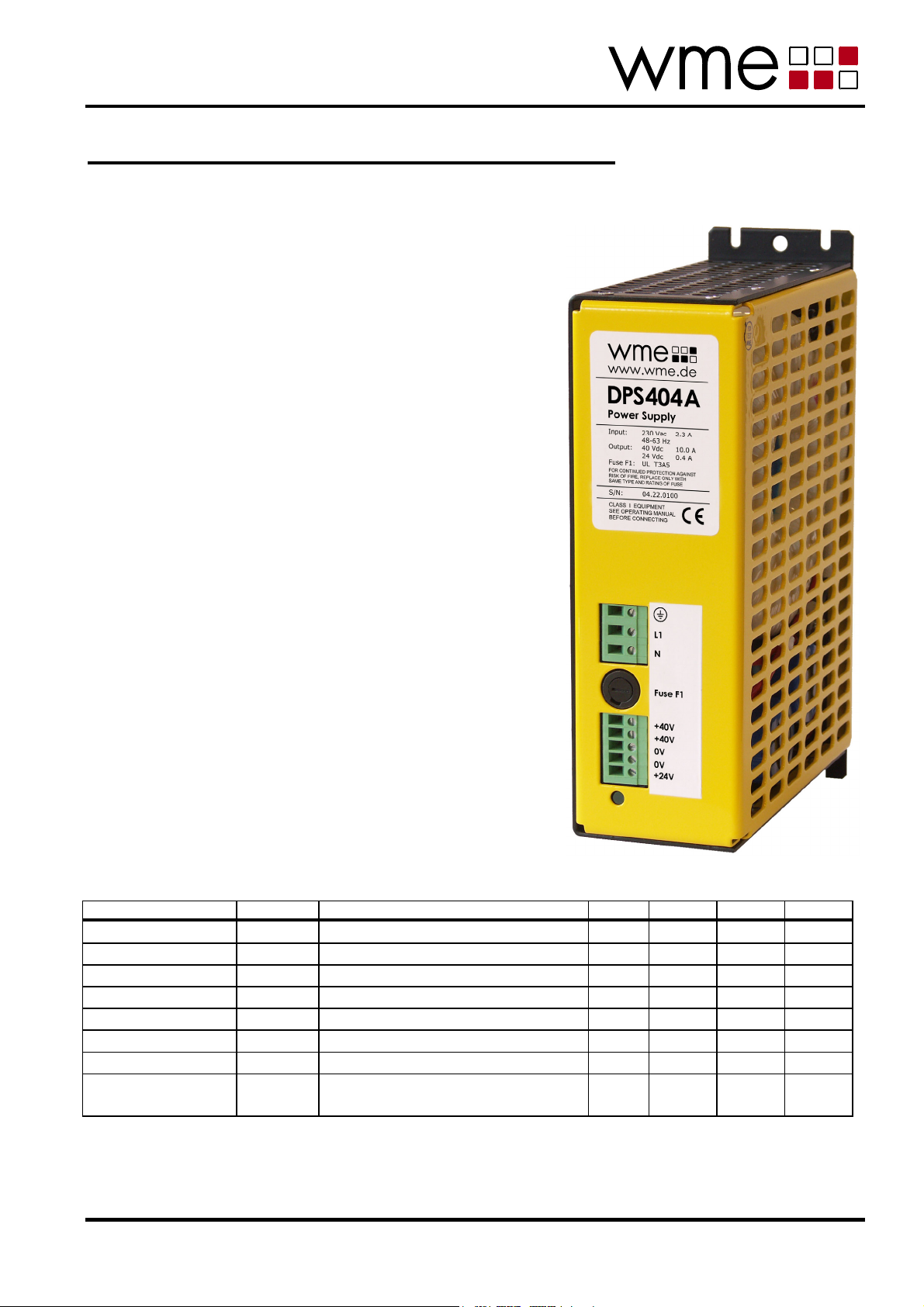
WME DPS404A User manual

DPS404A_MANUAL 06/2014 Seite 1 von 16
WME Power Systems GmbH
Ohleckerring 40 yD-22419 Hamburg yGermany y+49 40 527 4091 y+49 40 527 4093 y[email protected] ywww.wme.de
Datenblatt / Betriebsanleitung DPS404A
English version on page 7
•Stromversorgung für die
Antriebstechnik
•Ausgangsleistung 400W
•Ausgangsspannung 38V gesiebt
•Ausgangsstrom 10A
•Spitzenausgangsstrom bis zum
6-fachen Nennstrom
•integrierte Hilfsversorgung
24V / 0,4A geregelt
•stabiles Metallgehäuse zur
Wandmontage
•EN 60950; EN 50178; EN 60204
•CE
Elektrische Daten
Eingang
Parameter Symbol Bedingungen Min. Nom. Max. Einheit
Netzspannung UE195 230 253 VAC
Netzfrequenz fE48 50/60 65 Hz
Eingangsstrom IENennlast (IA= IAn) 2,9 Aeff
Einschaltstrom t < 30ms, Gerät kalt 40 AS
Ableitstrom 0,5 mA
Scheinleistung Nennlast (IA= IAn) 564 VA
Netzsicherung F1 UL248-14, träge, 250V 3,5 3,5 A
externe
Absicherung
16 16 A

DPS404A
DPS404A_MANUAL 06/2014 Seite 2 von 16
WME Power Systems GmbH
Ohleckerring 40 yD-22419 Hamburg yGermany y+49 40 527 4091 y+49 40 527 4093 y[email protected] ywww.wme.de
Ausgang Leistungsversorgung
Parameter Symbol Bedingungen Nom. Max. Einheit
IA= 0; UE= 230 VAC 44,5 VDC
IA= IAn; UE= 230 VAC 38,0 VDC
Ausgangsspannung UA
IA= 60,0 A; UE= 230 VAC 23,5 VDC
Ripple IA= IAn 3,5 VSS
= Nennstrom IAn 10,0 10,0 AAusgangsstrom IA
t < 0,5 s 160,0 A
Interne Ausgangskapazität CA20.000 µF
dauerhaft 63 VZulässige Ausgangsspan-
nung bei Rückspeisung 2
UARmax
t < 30 s, ED < 5% 70 V
Ausgang Hilfsversorgung
geregelter 24V Ausgang, z.B. zur Versorgung von Steuerbaugruppen
Parameter Symbol Bedingungen Nom. Max. Einheit
Ausgangsspannung UA24 I
A= 0,4 A; UE= 230 VAC 24,0 VDC
Ausgangsstrom IA24 0,4 A
Kurzschlussstrom IA24 1 A
Die Massen der Leistungs- und der Hilfsversorgung sind miteinander verbunden (0V).
Anschlüsse
Schraubklemmen PHOENIX FRONT
Anschlussdaten: primär 1,5 mm2, fein- / eindrähtig;
sekundär 2,5 mm2, fein- / eindrähtig.
Klemmleiste Position Verbindung
1 PE
2 L1
X1
3 N
1 +40V
2 +40V
3 0V
4 0V
X2
5 +24V
1s. Betriebshinweise
2Maximal zulässige Ausgangsspannung bei gleichzeitigem Kurzschluss auf dem
Ausgang der 24V-Hilfsversorgung: 60V

DPS404A
DPS404A_MANUAL 06/2014 Seite 3 von 16
WME Power Systems GmbH
Ohleckerring 40 yD-22419 Hamburg yGermany y+49 40 527 4091 y+49 40 527 4093 y[email protected] ywww.wme.de
Umgebungsdaten
Parameter Bedingungen Min. Max. Einheit
Umgebungstemperatur
- Betrieb Derating: -2%/ °C ab 35°C -25 +85 °C
- Transport und Lagerung -40 +85 °C
Luftfeuchtigkeit
- Betrieb nicht kondensierend 5 80 %
- Transport und Lagerung 5 95 %
Verschmutzungsgrad VDE 0110 T1 II
Sicherheitsdaten
Parameter Bemerkung Nom. Max. Einheit
Primär/ PE EN 60950 2 kV
Primär/ Sekundär 4 kV
Prüfspannung
Sekundär/ PE 500 V
Überspannungskategorie VDE 0110 T1 2
Ableitstrom EN 60950 0,5 mA
Schutzart EN 60529:1991 IP20
Schutzklasse VDE 0160 T1 I
Mechanische Daten
Parameter Typ. Einheit
Gesamthöhe 240 mm
Höhe ohne
Montagelaschen
213 mm
Breite 70 mm
Tiefe 164 mm
Gewicht ca. 6,5 kg
Technische Änderungen vorbehalten.

DPS404A
DPS404A_MANUAL 06/2014 Seite 4 von 16
WME Power Systems GmbH
Ohleckerring 40 yD-22419 Hamburg yGermany y+49 40 527 4091 y+49 40 527 4093 y[email protected] ywww.wme.de
Sicherheits- und Installationshinweise
Betriebsanleitung lesen! Bevor Sie mit dem Gerät arbeiten: Lesen Sie diese Anleitung komplett durch.
Stellen Sie sicher, dass Sie alles verstanden haben (Kollegen fragen)!
Hinweise am Gerät beachten!
Verpackung Bitte untersuchen Sie das Gerät vor Inbetriebnahme auf Transportschäden wie
Deformation und lose Teile. Beschädigungen sind unverzüglich beim
Transportunternehmen zu reklamieren; auch dann, wenn die Verpackung äußerlich
nicht beschädigt ist.
Zulässiger
Einsatzbereich
Dieses Gerät ist zum Einbau in Schaltschränke oder andere mechanische
Umhüllungen vorgesehen, die die Anforderungen für den Berührungsschutz gegen
gefährliche Spannungen und/oder Energien und den Brandschutz erfüllen müssen.
Es ist zur Verwendung in elektrische Anlagen oder Maschinen bestimmt ist und
erfüllt die Anforderungen der Niederspannungsrichtlinie (73/23/EWG). Bei Einbau in
Maschinen ist die Aufnahme des bestimmungsgemäßen Betriebes solange
untersagt, bis festgestellt wurde, daß die Maschine den Bestimmungen der
Maschinenrichtlinie (89/392/EWG) entspricht; EN 60204 ist zu beachten.
Anlage freischalten! Vor Installations-, Wartungs- oder Änderungsarbeiten: Schalten Sie Ihre Anlage
spannungsfrei. Stellen Sie sicher, dass sie nicht versehentlich wieder eingeschaltet
werden kann!
Fachgerechte
Installation!
Achtung! Unsachgemäße Installation/Betrieb kann die Sicherheit beeinträchtigen
und zu Betriebsstörungen bis hin zur Zerstörung des Gerätes führen.
Die Installation und Inbetriebnahme darf nur durch entsprechend qualifiziertes
Fachpersonal erfolgen. Hierbei sind die einschlägigen Vorschriften (DIN, VDE bzw.
landesspezifische Vorschriften) zu beachten.
Insbesondere ist vor der Inbetriebnahme sicherzustellen, dass:
• der Netzanschluß gemäß VDE0100 und VDE0160 erfolgt
• bei flexiblen Kabeln alle Feindrähte in den Anschlussklemmen befestigt sind
(Gefahr von Kurzschluß)
• Gerät und Zuleitungen ausreichend abgesichert werden. Eine Trenneinrichtung ist
für das Endgerät vorzusehen, so dass Gerät und Zuleitungen im Bedarfsfall
unterbrochen sind.
• der Schutzleiter an die Klemme angeschlossen wird
• alle Ausgangsleitungen für den Ausgangsstrom des Netzteils ausgelegt sind und
polrichtig angeschlossen werden.
• eine ausreichende Kühlung gewährleistet ist
Keine Änderungen im
Betrieb!
Solange sich das Gerät in Betrieb befindet dürfen keine Änderungen an der
Installation vorgenommen werden! Dies gilt auch für die Sekundärseite. Gefahr von
Lichtbögen und elektrischem Schlag (Lebensgefahr)!
Verbrennungsgefahr! Das Gerät wird im Betrieb heiß. Die linke Seitenfläche und die Rückseite können
Temperaturen > 60°C annehmen. Im Betrieb und kurz danach nicht berühren!
Restladung! Auch nach dem Ausschalten kann in den Ausgangskondensatoren noch mehrere
Minuten lang Energie gespeichert sein. Vor Arbeiten an der Verdrahtung abwarten,
bis die Betriebsanzeige erloschen ist.
Nicht öffnen! Das Gehäuse darf nicht geöffnet werden.
Montage Zulässige Einbaulage: senkrecht auf eine senkrecht stehende Montageplatte
geschraubt.
Ausreichend Freiraum zur Kühlung lassen!
Abstände zu benachbarten Geräten müssen rechts und links mindestens 30mm,
oben und unten mindestens 60mm betragen.
Bei unzureichender Luftzufuhr oder unsachgemäßem Einbau kann das Gerät im
Betrieb überhitzen. Um gefährliche Zustände zu vermeiden, ist der Trafo mit einer
Temperatursicherung ausgerüstet. Diese Temperatursicherung spricht dann an und
unterbricht den primärseitigen Stromfluss. Das Gerät ist danach nicht mehr
betriebsfähig.

DPS404A
DPS404A_MANUAL 06/2014 Seite 5 von 16
WME Power Systems GmbH
Ohleckerring 40 yD-22419 Hamburg yGermany y+49 40 527 4091 y+49 40 527 4093 y[email protected] ywww.wme.de
Anschluss • Nur handelsübliche, für die gegebenen Spannungen und Ströme ausgelegte
Kabel verwenden!
• Bei flexiblen Kabeln: Sicherstellen, daß alle Feindrähte des Kabels in der Klemme
befestigt sind.
• Verwendung von geeigneten Aderendhülsen ist zulässig.
• Polung der Ausgangsklemmen beachten!
Erdung • Nicht ohne angeschlossenen Schutzleiter betreiben!
Mit dem Netz verbundene Geräte der Schutzklasse I dürfen nicht ohne
ausreichende Erdung betrieben werden!
• Das Gehäuse ist mit der Erdungsklemme verbunden.
• Sekundärseite ist nicht geerdet. Bei Bedarf kann die „0V“-Klemme geerdet
werden.
Absicherung Das Gerät ist gegen Kurzschluss und Überlast mit einer primärseitigen
Schmelzsicherung (F1) geschützt. Bei Sicherungswechsel darf diese nur durch
Sicherungen des gleichen Typs und des gleichen Bemessungsstroms ersetzt
werden!
Rückspeisung Bei Rückspeisung durch ein angeschlossenes Antriebssystem (Bremsbetrieb)
dürfen die in den technischen Daten angegebenen Ausgangsspannungen
(dauerhaft/kurzzeitig) nicht überschritten werden.
Wartung Das Gerät benötigt keine regelmäßige Wartung. Bei erkennbaren
Staubablagerungen Gerät mit Pressluft niedrigen Drucks ausblasen.
Recycling Das Gerät enthält Bauteile, die wiederverwertet werden können, sowie Bauteile, die
speziell entsorgt werden müssen. Sorgen Sie deshalb dafür, dass das Gerät nach
seiner Verwendung der Wiederverwertung (Recycling) zugeführt wird.
Betriebshinweise
Ausgangsstrom Der Ausgang darf dauerhaft bis zum Nennstrom IAn belastet werden.
Die Angaben für kurzzeitig (t = 0,5 s) höhere Ausgangsströme sind für Überlast-
situationen gedacht, die selten auftreten (ED < 1%). Bei niedrigeren
Überlastströmen dürfen diese auch für längere Zeiten fließen. Zur Orientierung
können die folgenden Werte dienen, wobei eine Grundlast von 50% des
Nennstromes angenommen wird:
Ausgangsstrom Überlastdauer
200% Nennstrom 30 s
300% Nennstrom 2 s
400% Nennstrom 1 s
600% Nennstrom 0,5 s
Bei häufig oder periodisch auftretenden Überlastströmen darf der DC-Effektivwert
des Ausgangsstroms nicht größer sein, als der spezifizierte Nennstrom IAn.
Werden die angegebenen Grenzwerte überschritten, kann die Netzsicherung
durchbrennen.

DPS404A
DPS404A_MANUAL 06/2014 Seite 6 von 16
WME Power Systems GmbH
Ohleckerring 40 yD-22419 Hamburg yGermany y+49 40 527 4091 y+49 40 527 4093 y[email protected] ywww.wme.de

DPS404A
DPS404A_MANUAL 06/2014 Seite 7 von 16
WME Power Systems GmbH
Ohleckerring 40 yD-22419 Hamburg yGermany y+49 40 527 4091 y+49 40 527 4093 y[email protected] ywww.wme.de
Data Sheet / User Manual DPS404A
•Power Supply for drive technology
•Power output 400W
•Output voltage 38V filtered
•Output current 10A
•Peak output current up to six times
rated current
•Integrated Auxiliary Supply
24V / 0.4A regulated
•Robust metal case for wall
attachment
•EN 60950; EN 50178; EN 60204
•CE
Electrical data
Input
Parameter Symbol Conditions Min. Nom. Max. Unit
Supply voltage VIN 195 230 253 VAC
Frequency fIN 48 50/60 65 Hz
Input current IIN Rated load (IOUT = IOUTn) 2.9 Aeff
Inrush current t < 30ms, device cool 40 AS
Leakage current 0.5 mA
Apparent power Rated load (IOUT = IOUTn) 564 VA
Internal fuse F1 UL248-14, slow, 250V 3.5 3.5 A
External fuse 16 16 A

DPS404A
DPS404A_MANUAL 06/2014 Seite 8 von 16
WME Power Systems GmbH
Ohleckerring 40 yD-22419 Hamburg yGermany y+49 40 527 4091 y+49 40 527 4093 y[email protected] ywww.wme.de
Power Output
Parameter Symbol Conditions Nom. Max. Unit
IOUT = 0; VIN = 230 VAC 44.5 VDC
IOUT = IOUTn; VIN = 230 VAC 38.0 VDC
Output voltage VOUT
IOUT = 60.0 A; VIN = 230 VAC 23.5 VDC
Ripple IOUT = IOUTn 3.5 VSS
= Nominal current IOUTn 10.0 10.0 AOutput current IOUT
t < 0,5 s 360.0 A
Internal output capacity CO20.000 µF
continuous 63 VAllowable output voltage
during reverse feeding 4
VORmax
t < 30 s, Duty < 5% 70 V
Auxiliary Output
24V output, regulated, e.g. to supply control boards
Parameter Symbol Conditions Nom. Max. Unit
Output voltage VO24 I
OUT = 0.4 A; VIN = 230 VAC 24.0 VDC
Output current IO24 0.4 A
Short circuit current IO24 1 A
Grounds of power output and auxiliary output are connected (0V)
Connections
Screw connector PHOENIX FRONT
for both solid and stranded wire; X1: 1.5 mm2; X2: 2.5 mm2.
Terminal strip Position Pin assignment
1 PE
2 L1
X1
3 N
1 +40V
2 +40V
3 0V
4 0V
X2
5 +24V
3see Operational notes
4Maximum allowable output voltage during short circuit applied
to the auxiliary output is 60V.

DPS404A
DPS404A_MANUAL 06/2014 Seite 9 von 16
WME Power Systems GmbH
Ohleckerring 40 yD-22419 Hamburg yGermany y+49 40 527 4091 y+49 40 527 4093 y[email protected] ywww.wme.de
Ambient Area
Parameter Conditions Min. Max. Unit
Ambient temperature
- Operation Derating: -2%/ °C starting at 35°C -25 +85 °C
- Transport and storage -40 +85 °C
Humidity
- Operation No condensation 5 80 %
- Transport and storage 5 95 %
Impurity concentration VDE 0110 T1 II
Safety
Parameter Comment Nom. Max. Unit
Primary / PE EN 60950 2 kV
Primary / secondary 4 kV
Test voltage
Secondary / PE 500 V
Overvoltage class VDE 0110 T1 2
Leakage current EN 60950 0.5 mA
Mechanical protective class EN 60529:1991 IP20
Electrical protective class VDE 0160 T1 I
Dimensions
Parameter Typ. Unit
Entire height 240 mm
Height without attach
flanges
213 mm
Width 70 mm
Depth 164 mm
Weight appr. 6.5 kg
Specifications are subject to change without notice.

DPS404A
DPS404A_MANUAL 06/2014 Seite 10 von 16
WME Power Systems GmbH
Ohleckerring 40 yD-22419 Hamburg yGermany y+49 40 527 4091 y+49 40 527 4093 y[email protected] ywww.wme.de
Safety notes and Installation
Read instructions! Before working with this unit, read these instructions carefully and completely. Make
sure that you have understood all the information (ask colleagues)! Comply with
notes on the unit!
Packaging Carefully check the equipment immediately after receipt for transport damage,
deformation and loose parts. Any damage should be reported without delay to the
transport carrier, even then when no apparent damage to external packaging is
visible.
Admissible area of
application
This unit is designed for use in panelboard installations or other building-in
applications where a suitable mechanical enclosure shall be provided to fulfill the
requirements for shockhazard protection and/or protection from hazardous energy
levels as well as for fire protection.
It is assigned for application in electrical installations or machines and it fulfills the
requirements of the low voltage directive (73/23/EWG). When installed into
machinery the normal operation is forbidden until it is ascertained that the machine
complies the requirements of the machinery directive (89/392/EWG); attention must
be paid to EN60204
Disconnect system
from supply network!
Before any installation, maintenance or modification work: Disconnect your system
from the supply network. Ensure that it cannot be re-connected inadvertently!
Before start of
operation:
Ensure appropriate
installation!
Warning! Improper installation/operation may impair safety and result in operational
difficulties or complete failure of the unit. The unit must be installed and put into
service by appropriately qualified personnel. Compliance with the relevant
regulations (DIN, VDE or specific national regulations) must be ensured. Before
operation is begun the following conditions must be ensured in particular:
• Connection to mains supply in compliance with VDE0100 and VDE0160
• With stranded wires: all strands must be secured in the terminal blocks (potential
danger of short circuit)
• Unit and power supply cables must be properly fused. A disconnecting device has
to be provided for the end product to disengage unit and supply cables from
supply mains if required
• The earth conductor must be non-fused and connected to the terminal
• All output lines must be rated for the power supply output current and must be
connected with the correct polarity
• Sufficient air-cooling must be ensured
In operation:
No modifications!
As long as the unit is in operation: do not modify the installation! The same applies
also to the secondary side (high current!). Risk of electric arcs and electric shock
(fatal)!
Risk of burns!
The unit becomes hot (particularly the rear side and the left side surfaces could
adopt temperatures > 60°C). Do not touch the unit in operation and shortly after
operation!
Stored energy! Even after switching off the device the output capacitors could remain charged for
several minutes. Do not manipulate the output connections while the operation
indicator is lit.
Do not open! The housing must not be opened.
Mounting Allowable installation position: screwed in vertical position on a vertical mounting
plate.
Leave sufficient space around the unit for cooling!
Leave a distance of at least 30mm on the right and left side and not less than 60mm
above and under the unit to neighbouring units.
Unsufficient air supply or inappropriate mounting could lead to overheating of the
unit during operation. To avoid hazardous states the transformer is equipped with a
temperature fuse. When the temperature fuse triggers it cuts off the current in the
primary side. Thereafter the unit is not operative any more.

DPS404A
DPS404A_MANUAL 06/2014 Seite 11 von 16
WME Power Systems GmbH
Ohleckerring 40 yD-22419 Hamburg yGermany y+49 40 527 4091 y+49 40 527 4093 y[email protected] ywww.wme.de
Connection • Use only commercial cables designed for the indicated voltage and current
values!
• With flexible cables: make sure that all cable strands are secured in the terminal.
• Suitable conductor terminal sleeves (ferrules) may be used.
• Ensure proper polarity at output terminals!
Grounding • Do not operate the unit without PE connection!
Units of protection class I that are connected to the mains must not be operated
without adequate earthing of the housing.
• The housing is connected to the earth terminal PE .
• The secondary side is not earthed; if necessary, the „0V“- terminal can be
earthed
Internal fuse The unit is protected against short circuit and overload with a fuse (F1) on the
primary side. The fuse must only be replaced by a fuse of the same type and the
same current rating!
Reverse feeding The specified output voltages (continuous / short-time) must not be exceeded by
reverse feeding through a connected drive system (braking operation)
Maintenance The unit does not need regular maintenance. If there are visible dust deposits clean
the unit with low pressure compressed air.
Recycling The unit contains elements which are suitable for recycling, and components which
need special disposal. You are therefore requested to make sure that the unit will
be recycled by the end of its service life.
Operational notes
Output current Continuous load must not exceed the nominal output current IOUTn.
The maximum permissible short time output current (t = 0.5 s) applies to seldom
occuring overload situations (duty rating < 1%). The lower the overload current the
longer the allowable time, as listed below. These approximate values hold true for a
basic load of 50% IOUTn.
Output current Overload duration
200% IOUTn 30 s
300% IOUTn 2 s
400% IOUTn 1 s
600% IOUTn 0.5 s
When overload appears often or periodically, the effective value of the output current
must not exceed the nominal output current IOUTn.
Exceeding the specified limit values may cause the mains fuse to blow.

DPS404A
DPS404A_MANUAL 06/2014 Seite 12 von 16
WME Power Systems GmbH
Ohleckerring 40 yD-22419 Hamburg yGermany y+49 40 527 4091 y+49 40 527 4093 y[email protected] ywww.wme.de

DPS404A
DPS404A_MANUAL 06/2014 Seite 13 von 16
WME Power Systems GmbH
Ohleckerring 40 yD-22419 Hamburg yGermany y+49 40 527 4091 y+49 40 527 4093 y[email protected] ywww.wme.de
EG-Konformitätserklärung
Hiermit erklären wir, dass die Bauart der nachfolgend bezeichneten Gerätefamilie in der von uns
in den Verkehr gebrachten Ausführung den wesentlichen Anforderungen der unten genannten
EG-Richtlinien entspricht.
Bezeichnung: DPS400 - Familie, Stromversorgung 400W
Typen: DPS402, DPS404, DPS404A, DPS405,
DPS406, DPS410
Einschlägige EG-Richtlinien:
Niederspannungsrichtlinie 73/23/EWG und deren Änderungsrichtlinien
EMV-Richtlinie 89/336/EWG und deren Änderungsrichtlinien
Folgende Normen wurden zur Beurteilung der Geräte hinsichtlich der oben genannten Richtlinien
herangezogen:
EN60950 A1-A4+A11: 97 Sicherheit von Einrichtungen der Informationstechnik
EN50178: 1998 Ausrüstung von Starkstromanlagen mit elektronischen
Betriebsmitteln
EN60204-1: 1998 Elektrische Ausrüstung von Maschinen
EN61000-6-2: 2002 Elektromagnetische Verträglichkeit – Störfestigkeit für
Industriebereich
EN55022 A1: 2000 Grenzwerte und Messverfahren für Funkstörungen von
Einrichtungen der Informationstechnik
EN61000-3-2: 2000 Elektromagnetische Verträglichkeit - Grenzwerte für
Oberschwingungsströme (Geräte-Eingangsstrom ≤16A je Leiter)
Hamburg, 2006-04-19
Wulf Müller
Geschäftsführer

DPS404A
DPS404A_MANUAL 06/2014 Seite 14 von 16
WME Power Systems GmbH
Ohleckerring 40 yD-22419 Hamburg yGermany y+49 40 527 4091 y+49 40 527 4093 y[email protected] ywww.wme.de

DPS404A
DPS404A_MANUAL 06/2014 Seite 15 von 16
WME Power Systems GmbH
Ohleckerring 40 yD-22419 Hamburg yGermany y+49 40 527 4091 y+49 40 527 4093 y[email protected] ywww.wme.de

DPS404A
DPS404A_MANUAL 06/2014 Seite 16 von 16
WME Power Systems GmbH
Ohleckerring 40 yD-22419 Hamburg yGermany y+49 40 527 4091 y+49 40 527 4093 y[email protected] ywww.wme.de
WME Power Systems GmbH
Oehleckerring 40
D-22419 Hamburg
Tel: 040-527 40 91
Fax: 040-527 40 93
www.wme.de
Table of contents
Languages:
Popular Power Supply manuals by other brands

StarTech.com
StarTech.com ATX2POWER430 instruction manual

EGS
EGS Appleton JBR Series Instruction for installation and maintenance

ASL INTERCOM
ASL INTERCOM PS 289 user manual

Simaudio
Simaudio MOON 320S owner's manual

Tequipment
Tequipment PSP-603 user manual

Spellman
Spellman MXR20PN24 Installation and user guide