PR PRetrans 5106 User manual

Programmable displays with a wide
selection of inputs and outputs for display of temperature,
volume and weight, etc. Feature linearisation, scaling,
and difference measurement functions for programming
via PReset software.
Displays
A wide selection of transmitters for DIN
form B mounting and DIN rail modules with analogue
and digital bus communication ranging from application-
specic to universal transmitters.
Temperature
Galvanic isolators for analogue and digital
signals as well as HART®signals. A wide product range
with both loop-powered and universal isolators featuring
linearisation, inversion, and scaling of output signals.
Isolation
Interfaces for analogue and digital signals
as well as HART®signals between sensors / I/P converters /
frequency signals and control systems in Ex zone 0, 1 & 2
and for some modules in zone 20, 21 & 22.
Ex interfaces
PC or front programmable modules with
universal options for input, output and supply. This range
offers a number of advanced features such as process
calibration, linearisation and auto-diagnosis.
Universal
DK
UK
FR
DE
Side 1
Page 15
Page 29
Seite 43
SIGNALS THE BEST
5106
HART®transparent
Repeater
No. 5106V103-IN
From ser. no. 030459198

1
HART®-TRANSPARENT REPEATER
PRetrans 5106
Indholdsfortegnelse
Advarsler ............................................................................ 2
Sikkerhedsregler................................................................. 3
EF-overensstemmelseserklæring....................................... 5
Adskillelse af SYSTEM 5000.............................................. 6
Anvendelse......................................................................... 7
Teknisk karakteristik ........................................................... 7
Montage / installation......................................................... 7
Applikationer ...................................................................... 8
Bestillingsskema................................................................. 9
Elektriske specifikationer.................................................... 9
Tilslutninger ........................................................................ 12
Blokdiagram ....................................................................... 13
Appendix:
UL Control Drawing No. 5106QU01................................... 57

2 3
SIGNATURFORKLARING
Trekant med udråbstegn: Advarsel / krav. Hændelser der kan føre til
livstruende situationer.
CE-mærket er det synlige tegn på modulets overensstemmelse med EU
-direktivernes krav.
Dobbelt isolation er symbolet for, at modulet overholder ekstra krav til
isolation.
Ex - Modulet er godkendt efter ATEX-direktivet til brug i forbindelse med
installationer i eksplosionsfarlige områder.
SIKKERHEDSREGLER
DEFINITIONER:
Farlige spændinger er defineret som områderne: 75...1500 Volt DC og
50...1000 Volt AC.
Teknikere er kvalificerede personer, som er uddannet eller oplært til at kunne
udføre installation, betjening eller evt. fejlfinding både teknisk og sikkerheds-
mæssigt forsvarligt.
Operatører er personer, som under normal drift med produktet skal indstille og
betjene produktets trykknapper eller potentiometre, og som er gjort bekendt
med indholdet af denne manual.
MODTAGELSE OG UDPAKNING:
Udpak modulet uden at beskadige det. Kontrollér ved modtagelsen, at modul-
typen svarer til den bestilte. Indpakningen bør følge modulet, indtil dette er
monteret på blivende plads.
MILJØFORHOLD:
Undgå direkte sollys, kraftigt støv eller varme, mekaniske rystelser og stød, og
udsæt ikke modulet for regn eller kraftig fugt. Om nødvendigt skal opvarmning,
udover de opgivne grænser for omgivelsestemperatur, forhindres ved hjælp af
ventilation.
Alle moduler hører til Installationskategori II, Forureningsgrad 1 og Isolations-
klasse II.
ADVARSEL
Dette modul er beregnet for tilslutning til livsfarlige elektriske
spændinger. Hvis denne advarsel ignoreres, kan det føre til
alvorlig legemsbeskadigelse eller mekanisk ødelæggelse.
For at undgå faren for elektriske stød og brand skal manualens
sikkerhedsregler overholdes, og vejledningerne skal følges.
Specifikationerne må ikke overskrides, og modulet må kun
benyttes som beskrevet i det følgende.
Manualen skal studeres omhyggeligt, før modulet tages i brug.
Kun kvalificeret personale (teknikere) må installere dette modul.
Hvis modulet ikke benyttes som beskrevet i denne manual, så
forringes modulets beskyttelsesforanstaltninger.
ADVARSEL
Der må ikke tilsluttes farlig spænding til modulet, før dette
er fastmonteret, og følgende operationer bør kun udføres på
modulet i spændingsløs tilstand og under ESD-sikre forhold:
Adskillelse af modulet for indstilling af omskiftere og jumpere.
Installation, ledningsmontage og -demontage.
Fejlfinding på modulet.
Reparation af modulet og udskiftning af sikringer må kun
foretages af PR electronics A/S.
ADVARSEL
SYSTEM 5000 skal monteres på DIN-skinne efter DIN 46277.
Kommunikationsstikket i SYSTEM 5000 har forbindelse til ind-
gangsklemmer, hvor der kan forekomme farlige spændinger, og
det må kun tilsluttes programmeringsenheden Loop Link via det
medfølgende kabel.
GENERELT
FARLIG
SPÆNDING
INSTAL-
LATION

4 5
EF-OVERENSSTEMMELSESERKLÆRING
Som producent erklærer
PR electronics A/S
Lerbakken 10
DK-8410 Rønde
hermed at følgende produkt:
Type: 5106
Navn: HART®-transparent repeater
er i overensstemmelse med følgende direktiver og standarder:
EMC-direktivet 2004/108/EF og senere tilføjelser
EN 61326-1 : 2006
For specifikation af det acceptable EMC-niveau henvises til modulets
elektriske specifikationer.
Lavspændingsdirektivet 2006/95/EF og senere tilføjelser
EN 61010-1 : 2001
ATEX-direktivet 94/9/EF og senere tilføjelser
EN 50014 : 1997 E inkl. A1+A2, EN 50020 : 2002 E
og EN 50281-1-1 : 1998 inkl. A1
ATEX-certifikat: DEMKO 00ATEX127483 (5106B)
Der kræves ingen ændringer i produktet for at opnå overensstemmelse med de
nye standarder:
EN 60079-0 : 2009 og EN 60079-11 : 2012
EN 61241-0 : 2006 og EN 61241-11 : 2006
Bemyndiget organ:
UL International Demko A/S
Lyskaer 8
P.O. Box 514
2730 Herlev
Danmark
Rønde, 14. september 2012 Kim Rasmussen
Producentens underskrift
INSTALLATION:
Modulet må kun tilsluttes af teknikere, som er bekendte med de tekniske
udtryk, advarsler og instruktioner i manualen, og som vil følge disse.
Hvis der er tvivl om modulets rette håndtering, skal der rettes henvendelse til
den lokale forhandler eller alternativt direkte til:
PR electronics A/S, Lerbakken 10, 8410 Rønde, Danmark tlf: +45 86 37 26 77.
Installation og tilslutning af modulet skal følge landets gældende regler for
installation af elektrisk materiel bl.a. med hensyn til ledningstværsnit, for-sikring
og placering.
Beskrivelse af indgang / udgang og forsyningsforbindelser findes på blokdia-
grammet og sideskiltet.
For moduler, som er permanent tilsluttet farlig spænding, gælder:
For-sikringens maksimale størrelse er 10 A og skal sammen med en afbryder
placeres let tilgængeligt og tæt ved modulet. Afbryderen skal mærkes
således, at der ikke er tvivl om, at den afbryder spændingen til modulet.
Produktionsår fremgår af de to første cifre i serienummeret.
KALIBRERING OG JUSTERING:
Under kalibrering og justering skal måling og tilslutning af eksterne spændinger
udføres i henhold til denne manual, og teknikeren skal benytte sikkerhedsmæs-
sigt korrekte værktøjer og instrumenter.
BETJENING UNDER NORMAL DRIFT:
Operatører må kun indstille eller betjene modulerne, når disse er fast installeret
på forsvarlig måde i tavler el. lignende, så betjeningen ikke medfører fare for liv
eller materiel. Dvs., at der ikke er berøringsfare, og at modulet er placeret, så
det er let at betjene.
RENGØRING:
Modulet må, i spændingsløs tilstand, rengøres med en klud let fugtet med
destilleret vand.
ANSVAR:
I det omfang instruktionerne i denne manual ikke er nøje overholdt, vil kunden
ikke kunne rette noget krav, som ellers måtte eksistere i henhold til den indgå-
ede salgsaftale, mod PR electronics A/S.

6 7
HART®-TRANSPARENT REPEATER
PRetrans 5106
• 3- / 5-port 3,75 kVAC galvanisk isolation
• Lav reaktionstid
• 2-trådsforsyning > 17 V
• 1- eller 2-kanals version
• Universel forsyning med AC eller DC
Anvendelse:
• SpændingsforsyningogsignalisolatormedtovejsHART®-kommunikation for
2-trådstransmittere.
• SignalisolatormedtovejsHART®-kommunikation for forsynede strømtrans-
mittere.
• Signalisolatormedlavreaktionstidpåanalogestrømsignaler.
Teknisk karakteristik:
• PR5106behandlerprimærtstrømsignalerpå4...20mA.
• PR5106benyttermikroprocessorteknologitilforstærkningognulpunktsfor-
skydning. Det analoge signal overføres med en reaktionstid på under 25 ms.
• Indgange,udgangeogforsyningerindbyrdesgalvaniskadskilteogikkestel-
bundne.
• Udgangenkankoblessomaktivstrømtransmitterellersomen2-trådstrans-
mitter.
Montage / installation:
• MonterespåDIN-skinne,vertikaltellerhorisontalt.Modulernekanmonteres
uden indbyrdes afstand, hvilket svarer til 84 kanaler pr. meter.
• PR5106BanbefalessomEx-barrierefor5335Dog6335D.
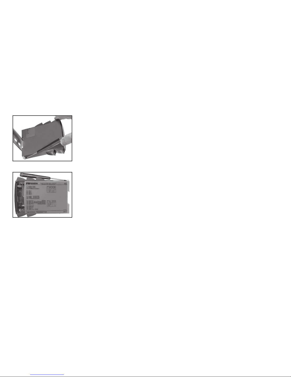
ADSKILLELSE AF SYSTEM 5000
Husk først at demontere tilslutningsklemmerne med farlig spænding.
Billede 1:
Modulet frigøres fra DIN-skinnen ved
at løfte i den nederste lås.
Billede 2:
Printet udtages ved at løfte i den
øverste lås og samtidig trække ud i
frontpladen.
Nu kan switche og jumpere ændres.

8 9
Elektriske specifikationer:
Specifikationsområde:
-20 til +60°C
Fælles specifikationer:
Forsyningsspænding, universel................... 21,6...253 VAC, 50...60 Hz eller
19,2...300 VDC
Egetforbrug.................................................. ≤2 W (2 kanaler)
Max. forbrug................................................ ≤3 W (2 kanaler)
Sikring ......................................................... 400 mA T / 250 VAC
Isolationsspænding, test / drift ................... 3,75 kVAC / 250 VAC
Signal- / støjforhold..................................... Min. 60 dB (0...100 kHz)
Reaktionstid (0...90%, 100...10%) .............. < 25 ms
Kalibreringstemperatur................................ 20...28°C
Virkning af forsyningsspændings-
ændring (24...250 V).................................... < ±10 µA
Nøjagtighed, størst af generelle og basisværdier:
5106 Standard : A
[EEx ia] II C : B
4…20 mA : B Enkelt : A
Dobbelt : B
Type Version Indgang Udgang Kanaler
Bestillingsskema: 5106
4…20 mA : 2
20...4 mA : 9
Forsyning
Forsyning
Strøm, mA
2-trådstransmitter
Udgang
Udgang
Basisværdier
Temperatur-
koefficient
Basis
nøjagtighed
Indgangstype
mA ≤±16 µA ≤±1,6 µA/°C
Generelle værdier
Temperatur-
koefficient
Absolut
nøjagtighed
Indgangstype
mA ≤±0,1% af span ≤±0,01% af span / °C

10 11
Ex- / I.S.-data:
Klemme 31...33
Um............................................................... : 250 V
Klemme 44 til 42, 41 (54 til 52, 51)
Uo................................................................ : 28 VDC
Io.................................................................. : 91 mADC
Po................................................................ : 0,65 W
Lo................................................................. : 3 mH
Co................................................................ : 80 nF
Klemme 41 til 42 (51 til 52)
Uo................................................................ : 10 VDC
Io.................................................................. : 2 mADC
Po................................................................ : 5 mW
Lo................................................................. : 1 H
Co................................................................ : 3 µF
GOST R godkendelse:
VNIIM & VNIIFTRI, Cert. no......................... Se www.prelectronics.dk
Overholdte myndighedskrav: Standard:
EMC 2004/108/EF....................................... EN 61326-1
LVD 2006/95/EF .......................................... EN 61010-1
PELV/SELV................................................... IEC 364-4-41 og EN 60742
ATEX 94/9/EF .............................................. EN 50014, EN 50020 og
EN 50281-1-1
UL................................................................ UL 913, UL 508
Af span = af det aktuelt valgte område
Hjælpespænding:
2-trådsforsyning
(klemme 44...42 & 54...52) .......................... 25...17 VDC / 0...20 mA
Ledningskvadrat (max.)............................... 1 x 2,5 mm2flerkoret ledning
Klemskruetilspændingsmoment.................. 0,5 Nm
Relativ luftfugtighed .................................... < 95% RH (ikke kond.)
Mål (HxBxD) ................................................ 109 x 23,5 x 130 mm
DIN-skinne type........................................... DIN 46277
Kapslingsklasse........................................... IP20
Vægt ............................................................ 246 g
Strømindgang:
Måleområde ................................................ 4...20 mA
Min. måleområde (span).............................. 16 mA
Indgangsmodstand:
Forsynet enhed ........................................... Nom. 10 Ω
Ikke-forsynet enhed .................................... Rshunt = ∞, Vdrop < 4 V
Strømudgang og 2-tråds 4...20 mA udgang:
Signalområde (span) ................................... 4...20 mA
Min. signalområde (span)............................ 16 mA
Belastning (max.)......................................... 20 mA / 600 Ω/ 12 VDC
Belastningsstabilitet .................................... ≤0,01% af span / 100 Ω
Strømbegrænsning...................................... ≤28 mA
Ripple på HART®-kommunikation............... < 3 mVRMS
Max. ekstern 2-trådsforsyning .................... 29 VDC
Virkning af ekstern 2-trådsforsynings-
spændingsændring ..................................... < 0,005% af span / V
EEx- / I.S.-godkendelse - 5106B:
DEMKO 00ATEX127483 .............................. II (1) GD
[EEx ia] IIC
Anvendes for ............................................... Zone 0, 1, 2, 20, 21 eller 22
UL................................................................ IS, Cl. I, Div. 1, Group A, B, C, D
IS, Cl. I, zone 0 and 1, Group IIC
IS, Cl. II, Div. 1, Group E, F, G
UL control drawing no. ........................ 5106QU01
EMC-immunitetspåvirkning................................. < ±0,5% af span
Udvidet EMC-immunitet:
NAMUR NE 21, A kriterium, gniststøj ................. < ±1% af span

12 13
BLOKDIAGRAM:
mA
5106
5106
0...20
mA
CH 1
CH 2
Tx
+
-
+
-
33
44
42
41
54
52
51
31
14
13
11
24
23
21
Vreg.
PTC
1 V
12
250 Ω
22
mA
+
Ex-barriere, kun 5106B
Kanal 1
Kanal 2
2-tråds-
installation
Forsyning
Forsyning
I+, Udgang
24...230 VAC &
24...250 VDC
2-trådsforsyning
Indgang gnd.
Indgang +,I
Gnd.
33
31
COMMUNICATION FOUNDATION
41 / 51
42 / 52
43 / 53
44 / 54
COMMUNICATION FOUNDATION
41 / 51
42 / 52
43 / 53
44 / 54
COMMUNICATION FOUNDATION
14 / 24
13 / 23
12 / 22
11 / 21
Z
250 Ω
COMMUNICATION FOUNDATION
14 / 24
13 / 23
12 / 22
11 / 21
Z
250 Ω
COMMUNICATION FOUNDATION
14 / 24
13 / 23
12 / 22
11 / 21
Z
250 Ω
Z
COMMUNICATION FOUNDATION
14 / 24
13 / 23
12 / 22
11 / 21
250 Ω
Tilslutninger:
Forsyning:
Udgange:
Indgange:
Indgang
Indgang
DCS / PLC
Hvis indgangsimpedansen Z er 250 Ωeller højere
Passiv
udgang DCS / PLC
DCS / PLC
Strøm
DCS / PLC
Hvis indgangsimpedansen Z er < 250 Ω
Aktiv
udgang
Ind-
gang
Udgang
Aktiv
udgang
Passiv
udgang
Ind-
gangUdgang
Hvis indgangsimpedansen Z er < 250 ΩHvis indgangsimpedansen Z er 250 Ωeller højere
Indgang
Udgang
Indgang
Udgang
2-trådstransmitter
24...230 VAC &
24...250 VDC
Tilslutning er identisk
for kanal 1 og kanal 2.

14 15
HART®TRANSPARENT REPEATER
PRetrans 5106
Table of contents
Warnings ............................................................................ 16
Safety instructions.............................................................. 17
EC Declaration of Conformity ............................................ 19
How to demount SYSTEM 5000........................................ 20
Application ......................................................................... 21
Technical characteristics .................................................... 21
Mounting / installation........................................................ 21
Applications........................................................................ 22
Order .................................................................................. 23
Electrical specifications...................................................... 23
Connections ....................................................................... 26
Block diagram .................................................................... 27
Appendix:
UL Control Drawing No. 5106QU01................................... 57

16 17
SYMBOL IDENTIFICATION
Triangle with an exclamation mark: Warning / demand. Potentially
lethal situations.
The CE mark proves the compliance of the module with the essential
requirements of the directives.
The double insulation symbol shows that the module is protected by
double or reinforced insulation.
Ex modules have been approved for use in connection with installations
in explosive areas.
SAFETY INSTRUCTIONS
DEFINITIONS:
Hazardous voltages have been defined as the ranges: 75 to 1500 Volt DC, and
50 to 1000 Volt AC.
Technicians are qualified persons educated or trained to mount, operate, and
also troubleshoot technically correct and in accordance with safety regulations.
Operators, being familiar with the contents of this manual, adjust and operate
the knobs or potentiometers during normal operation.
RECEIPT AND UNPACKING:
Unpack the module without damaging it. The packing should always follow the
module until this has been permanently mounted. Check at the receipt of the
module whether the type corresponds to the one ordered.
ENVIRONMENT:
Avoid direct sunlight, dust, high temperatures, mechanical vibrations and shock,
as well as rain and heavy moisture. If necessary, heating in excess of the stated
limits for ambient temperatures should be avoided by way of ventilation.
All modules fall under Installation Category II, Pollution Degree 1, and Insulation
Class II.
MOUNTING:
Only technicians who are familiar with the technical terms, warnings, and
instructions in the manual and who are able to follow these should connect the
module.
WARNING!
This module is designed for connection to hazardous electric
voltages.
Ignoring this warning can result in severe personal injury or
mechanical damage.
To avoid the risk of electric shock and fire, the safety
instructions of this manual must be observed and the guidelines
followed. The specifications must not be exceeded, and the
module must only be applied as described in the following.
Prior to the commissioning of the module, this manual must be
examined carefully.
Only qualified personnel (technicians) should install this module.
If the equipment is used in a manner not specified by the
manufacturer, the protection provided by the equipment may be
impaired.
WARNING!
Until the module is fixed, do not connect hazardous voltages to
the module.
The following operations should only be carried out on a
disconnected module and under ESD safe conditions:
Dismantlement of the module for setting of DIP-switches
and jumpers.
General mounting, connection and disconnection of wires.
Troubleshooting the module.
Repair of the module and replacement of circuit breakers
must be done by PR electronics A/S only.
WARNING!
SYSTEM 5000 must be mounted on DIN rail according to DIN
46277.
The communication connector of SYSTEM 5000 is connected
to the input terminals on which dangerous voltages can occur,
and it must only be connected to the programming unit Loop
Link by way of the enclosed cable.
GENERAL
HAZARD-
OUS
VOLTAGE
INSTAL-
LATION

18 19
EC DECLARATION OF CONFORMITY
As manufacturer
PR electronics A/S
Lerbakken 10
DK-8410 Rønde
hereby declares that the following product:
Type: 5106
Name: HART®transparent repeater
is in conformity with the following directives and standards:
The EMC Directive 2004/108/EC and later amendments
EN 61326-1 : 2006
For specification of the acceptable EMC performance level, refer to the
electrical specifications for the module.
The Low Voltage Directive 2006/95/EC and later amendments
EN 61010-1 : 2001
The ATEX Directive 94/9/EC and later amendments
EN 50014 : 1997 E incl. A1+A2, EN 50020 : 2002 E
and EN 50281-1-1 : 1998 incl. A1
ATEX certificate: DEMKO 00ATEX127483 (5106B)
No changes are required to enable compliance with the replacement standards:
EN 60079-0 : 2009 and EN 60079-11 : 2012
EN 61241-0 : 2006 and EN 61241-11 : 2006
Notified body
UL International Demko A/S
Lyskær 8
P.O. Box 514
2730 Herlev
Denmark
Rønde, 14 September 2012 Kim Rasmussen
Manufacturer’s signature
Should there be any doubt as to the correct handling of the module, please
contact your local distributor or, alternatively,
PR electronics A/S, Lerbakken 10, DK-8410 Rønde, Denmark,
tel: +45 86 37 26 77.
Mounting and connection of the module should comply with national legislation
for mounting of electric materials, i.e. wire cross section, protective fuse, and
location. Descriptions of input / output and supply connections are shown in
the block diagram and side label.
The following apply to fixed hazardous voltages-connected modules:
The max. size of the protective fuse is 10 A and, together with a power
switch, it should be easily accessible and close to the module. The
power switch should be marked with a label telling it will switch off the
voltage to the module.
Year of manufacture can be taken from the first two digits in the serial number.
CALIBRATION AND ADJUSTMENT:
During calibration and adjustment, the measuring and connection of external
voltages must be carried out according to the specifications of this manual. The
technician must use tools and instruments that are safe to use.
NORMAL OPERATION:
Operators are only allowed to adjust and operate modules that are safely fixed
in panels, etc., thus avoiding the danger of personal injury and damage. This
means there is no electrical shock hazard, and the module is easily accessible.
CLEANING:
When disconnected, the module may be cleaned with a cloth moistened with
distilled water.
LIABILITY:
To the extent the instructions in this manual are not strictly observed, the
customer cannot advance a demand against PR electronics A/S that would
otherwise exist according to the concluded sales agreement.

20 21
HART®TRANSPARENT REPEATER
PRetrans 5106
• 3- / 5-port 3.75 kVAC galvanic isolation
• Low response time
• 2-wire supply > 17 V
• 1- or 2-channel version
• Universal AC or DC supply
Application:
• Powersupplyandsignalisolatorwith2-wayHART® communication for 2-wire
transmitters.
• Signalisolatorwith2-wayHART® communication for supplied current
transmitters.
• Signalisolatorwithlowresponsetimeonanaloguecurrentsignals.
Technical characteristics:
• PR5106primarilyprocessescurrentsignalsof4...20mA.
• PR5106isbasedonmicroprocessortechnologyforgainandoffset.The
analogue signal is transmitted at a response time of less than 25 ms.
• Inputs,outputs,andsupplyarefloatingandgalvanicallyseparated.
• Theoutputcanbeconnectedeitherasanactivecurrenttransmitterorasa
2-wire transmitter.
Mounting / installation:
• MountedverticallyorhorizontallyonaDINrail.Asthemodulescanbemount-
ed without distance between neighbouring units, up to 84 channels can be
mounted per metre.
• PR5106BisrecommendedasExsafetybarrierfor5335Dand6335D.
HOW TO DEMOUNT SYSTEM 5000
First, remember to demount the connectors with hazardous voltages.
Picture 1:
By lifting the bottom lock, the module
is detached from the DIN rail.
Picture 2:
Then, by lifting the upper lock
and pulling the front plate
simultaneously, the PCB is removed.
Switches and jumpers can now be
adjusted.

22 23
Electrical specifications:
Specifications range:
-20 to +60°C
Common specifications:
Supply voltage universal ............................. 21.6...253 VAC, 50...60 Hz or
19.2...300 VDC
Internal consumption .................................. ≤2 W (2 channels)
Max. consumption....................................... ≤3 W (2 channels)
Fuse............................................................. 400 mA SB / 250 VAC
Isolation voltage, test / operation ............... 3.75 kVAC / 250 VAC
Signal / noise ratio ...................................... Min. 60 dB (0...100 kHz)
Response time (0...90%, 100...10%) .......... < 25 ms
Calibration temperature............................... 20...28°C
Effect of supply voltage
change (24...250 V) ..................................... < ±10 µA
Accuracy, the greater of general and basic values:
5106 Standard : A
[EEx ia] II C : B
4…20 mA : B Single : A
Double : B
Type Version Input Output Channels
Order: 5106
4…20 mA : 2
20...4 mA : 9
Supply
Supply
Current, mA
2-wire transmitter
Output
Output
Basic values
Temperature
coefficient
Basic
accuracy
Input type
mA ≤±16 µA ≤±1.6 µA/°C
General values
Temperature
coefficient
Absolute
accuracy
Input type
mA ≤±0.1% of span ≤±0.01% of span / °C

24 25
Ex / I.S. data:
Terminal 31...33
Um............................................................... : 250 V
Terminal 44 to 42, 41 (54 to 52, 51)
Uo................................................................ : 28 VDC
Io.................................................................. : 91 mADC
Po................................................................ : 0.65 W
Lo................................................................. : 3.0 mH
Co................................................................ : 80 nF
Terminal 41 to 42 (51 to 52)
Uo................................................................ : 10 VDC
Io.................................................................. : 2 mADC
Po................................................................ : 5 mW
Lo................................................................. : 1 H
Co................................................................ : 3 µF
GOST R approval:
VNIIM & VNIIFTRI, Cert. no......................... See www.prelectronics.com
Observed authority requirements: Standard:
EMC 2004/108/EC ...................................... EN 61326-1
LVD 2006/95/EC.......................................... EN 61010-1
PELV/SELV................................................... IEC 364-4-41
and EN 60742
ATEX 94/9/EC.............................................. EN 50014, EN 50020 and
EN 50281-1-1
UL................................................................ UL 913, UL 508
Of span = of the presently selected range
Auxiliary supply:
2-wire supply (pin 44...42 & 54...52) ........... 25...17 VDC / 0...20 mA
Max. wire size.............................................. 1 x 2.5 mm2stranded wire
Screw terminal torsion ................................ 0.5 Nm
Relative humidity......................................... < 95% RH (non-cond.)
Dimensions (HxWxD)................................... 109 x 23.5 x 130 mm
DIN rail type................................................. DIN 46277
Protection degree........................................ IP20
Weight ......................................................... 246 g
Current input:
Measurement range .................................... 4...20 mA
Min. measurement range (span).................. 16 mA
Input resistance:
Supplied unit ............................................... Nom. 10 Ω
Non-supplied unit........................................ Rshunt = ∞, Vdrop < 4 V
Current output and 2-wire 4...20 mA output:
Signal range (span)...................................... 4...20 mA
Min. signal range (span) .............................. 16 mA
Load (max.).................................................. 20 mA / 600 Ω/ 12 VDC
Load stability............................................... ≤0.01% of span / 100 Ω
Current limit................................................. ≤28 mA
Ripple on HART®communication ............... < 3 mVRMS
Max. external 2-wire supply........................ 29 VDC
Effect of external 2-wire supply
voltage change............................................ < 0.005% of span / V
EEx / I.S. approval - 5106B:
DEMKO 00ATEX127483 .............................. II (1) GD
[EEx ia] IIC
Applicable for .............................................. Zone 0, 1, 2, 20, 21 or 22
UL................................................................ IS, Cl. I, Div. 1, Group A, B, C, D
IS, Cl. I, zone 0 and 1, Group IIC
IS, Cl. II, Div. 1, Group E, F,G
UL control drawing no. ........................ 5106QU01
EMC immunity influence ..................................... < ±0.5% of span
Extended EMC immunity:
NAMUR NE 21, A criterion, burst ....................... < ±1% of span

26 27
BLOCK DIAGRAM:
mA
5106
5106
0...20
mA
CH 1
CH 2
Tx
+
-
+
-
33
44
42
41
54
52
51
31
14
13
11
24
23
21
Vreg.
PTC
1 V
12
250 Ω
22
mA
+
Channel 1
Channel 2
Supply
Supply
I+, Output
Gnd.
2-wire supply
Input gnd.
Input +, I
2-wire
installation
24...230 VAC &
24...250 VDC
Ex barrier, only 5106B
33
31
COMMUNICATION FOUNDATION
41 / 51
42 / 52
43 / 53
44 / 54
COMMUNICATION FOUNDATION
41 / 51
42 / 52
43 / 53
44 / 54
COMMUNICATION FOUNDATION
14 / 24
13 / 23
12 / 22
11 / 21
Z
250 Ω
COMMUNICATION FOUNDATION
14 / 24
13 / 23
12 / 22
11 / 21
Z
250 Ω
COMMUNICATION FOUNDATION
14 / 24
13 / 23
12 / 22
11 / 21
Z
250 Ω
Z
COMMUNICATION FOUNDATION
14 / 24
13 / 23
12 / 22
11 / 21
250 Ω
Connections:
Supply:
Outputs:
Inputs:
Input
Input
DCS / PLC
If the input impedance Z is 250 Ωor higher
Passive
output DCS / PLC
DCS / PLC
Current
DCS / PLC
If the input impedance Z is < 250 Ω
Active
output
Input
Output
Active
output
Passive
output
Input
Output
If the input impedance Z is < 250 ΩIf the input impedance Z is 250 Ωor higher
Input
Output
Input
Output
2-wire transmitter
24...230 VAC &
24...250 VDC
Connections are identical
for channel 1 and channel 2.

28 29
ISOLATEUR / TRANSPARENCE HART®
PRetrans 5106
SOMMAIRE
Avertissements................................................................... 30
Consignes de sécurité ....................................................... 31
Déclaration de conformité CE............................................ 33
Démontage du SYSTEME 5000......................................... 34
Application ......................................................................... 35
Caractéristiques techniques............................................... 35
Montage / installation......................................................... 35
Applications........................................................................ 36
Référence ........................................................................... 37
Spécifications électriques .................................................. 37
Connexions ........................................................................ 40
Schéma de principe ........................................................... 41
Appendix:
UL Control Drawing No. 5106QU01................................... 57

30 31
SIGNIFICATION DES SYMBOLES
Triangle avec point d’exclamation : Attention ! Si vous ne respectez pas
les instructions, la situation pourrait être fatale.
Le signe CE indique que le module est conforme aux exigences des
directives.
Ce symbole indique que le module est protégé par une isolation double
ou renforcée.
L’utilisation des modules de type S.I. avec des installations situées dans
des zones à risques d’explosions à été autorisée.
CONSIGNES DE SECURITE
DEFINITIONS
Les gammes de tensions dangereuses sont les suivantes : de 75 à 1500 Vcc
et de 50 à 1000 Vca.
Les techniciens sont des personnes qualifiées qui sont capables de monter et
de faire fonctionner un appareil, et d’y rechercher les pannes, tout en respectant
les règles de sécurité.
Les opérateurs, connaissant le contenu de ce guide, règlent et actionnent les
boutons ou les potentiomètres au cours des manipulations ordinaires.
RECEPTION ET DEBALLAGE
Déballez le module sans l’endommager. Il est recommandé de conserver
l’emballage du module tant que ce dernier n’est pas définitivement monté. A la
réception du module, vérifiez que le type de module reçu correspond à celui que
vous avez commandé.
ENVIRONNEMENT
N’exposez pas votre module aux rayons directs du soleil et choisissez un endroit
à humidité modérée et à l’abri de la poussière, des températures élevées, des
chocs et des vibrations mécaniques et de la pluie. Le cas échéant, des systèmes
de ventilation permettent d’éviter qu’une pièce soit chauffée au-delà des limites
prescrites pour les températures ambiantes. Tous les modules appartiennent à
la catégorie d’installation Il, au degré de pollution I et à la classe d’isolation Il.
MONTAGE
Il est conseillé de réserver le raccordement du module aux techniciens qui
connaissent les termes techniques, les avertissements et les instructions de ce
guide et qui sont capables d’appliquer ces dernières.
AVERTISSEMENT!
Ce module est conçu pour supporter une connexion à des
tensions électriques dangereuses. Si vous ne tenez pas compte
de cet avertissement, cela peut causer des dommages corporels
ou des dégâts mécaniques.
Pour éviter les risques d’électrocution et d’incendie, conformez-
vous aux consignes de sécurité et suivez les instructions
mentionnées dans ce guide. Vous devez vous limiter aux
spécifications indiquées et respecter les instructions d’utilisation
de ce module, telles qu’elles sont décrites dans ce guide.
Il est nécessaire de lire ce guide attentivement avant de mettre
ce module en marche. L’installation de ce module est réservée à
un personnel qualifié (techniciens). Si la méthode d’utilisation de
l’équipement diffère de celle décrite par le fabricant, la protection
assurée par l’équipement risque d’être altérée.
AVERTISSEMENT!
Tant que le module n’est pas fixé, ne le mettez pas sous tensions
dangereuses. Les opérations suivantes doivent être effectuées
avec le module débranché et dans un environnement exempt de
décharges électrostatiques (ESD) : démontage du module pour
régler les commutateurs DIP et les cavaliers, montage général,
raccordement et débranchement de fils et recherche de pannes
sur le module.
Seule PR electronics SARL est autorisée à réparer le module
et à remplacer les disjoncteurs.
AVERTISSEMENT!
Il convient de monter l’appareil SYSTEME 5000 sur un rail DIN en
se conformant à la norme DIN 46277.
Le connecteur de communication du SYSTEME 5000 est relié
aux borniers d’entrée sur lesquelles peuvent se produire des
tensions dangereuses.
Ce connecteur doit uniquement être raccordé à l’appareil de
programmation Loop Link au moyen du câble blindé.
INFORMA-
TIONS
GENE-
RALES
TENSION
DANGE-
REUSE
INSTAL-
LATION

32 33
DECLARATION DE CONFORMITE CE
En tant que fabricant
PR electronics A/S
Lerbakken 10
DK-8410 Rønde
déclare que le produit suivant :
Type : 5106
Nom : Isolateur / transparence HART®
correspond aux directives et normes suivantes :
La directive CEM (EMC) 2004/108/CE et les modifications subséquentes
EN 61326-1 : 2006
Pour une spécification du niveau de rendement acceptable CEM (EMC)
renvoyer aux spécifications électriques du module.
La directive basse tension 2006/95/CE et les modifications subséquentes
EN 61010-1 : 2001
La directive ATEX 94/9/CE et les modifications subséquentes
EN 50014 : 1997 E incl. A1+A2, EN 50020 : 2002 E
et EN 50281-1-1 : 1998 incl. A1
Certificat ATEX : DEMKO 00ATEX127483 (5106B)
Aucune modification n’est exigée pour permettre la conformité aux normes de
remplacement :
EN 60079-0 : 2009 et EN 60079-11 : 2012
EN 61241-0 : 2006 et EN 61241-11 : 2006
Organisme notifié
UL International Demko A/S
Lyskær 8
P.O. Box 514
2730 Herlev
Danemark
Rønde, le 14 septembre 2012 Kim Rasmussen
Signature du fabricant
Si vous avez un doute quelconque quant à la manipulation du module, veuillez
contacter votre distributeur local. Vous pouvez également vous adresser à PR
electronics SARL, Zac du Chêne, Activillage, 4, allée des Sorbiers, F-69673
Bron Cedex (tél. : (0) 472 140 607)) ou à PR electronics A/S, Lerbakken 10,
DK-8410 Rønde, Danemark (tél. :+45 86 37 26 77).
Le montage et le raccordement du module doivent être conformes à la législation
nationale en vigueur pour le montage de matériaux électriques, par exemple
diamètres des fils, fusibles de protection et implantation des modules.
Les connexions des alimentations et des entrées / sorties sont décrites dans le
schéma de principe et sur l’étiquette de la face latérale du module.
Les instructions suivantes s’appliquent aux modules fixes connectés en tensions
dangereuses : Le fusible de protection doit être de 10 A au maximum. Ce dernier,
ainsi que l’interrupteur général, doivent être facilement accessibles et à proximité
du module. Il est recommandé de placer sur l’interupteur général une étiquette
indiquant que ce dernier mettra le module hors tension.
L’anne de production ressort des deux premiers chiffres du numéro de série.
ETALONNAGE ET REGLAGE
Lors des opérations d’étalonnage et de réglage, il convient d’effectuer les
mesures et les connexions des tensions externes en respectant les spécifications
mentionnées dans ce guide. Les techniciens doivent utiliser des outils et des
instruments pouvant être manipulés en toute sécurité.
MANIPULATIONS ORDINAIRES
Les opérateurs sont uniquement autorisés à régler et faire fonctionner des
modules qui sont solidement fixés sur des platines des tableaux, ect., afin
d’écarter les risques de dommages corporels. Autrement dit, il ne doit exister
aucun danger d’électrocution et le module doit être facilement accessible.
MAINTENANCE ET ENTRETIEN
Une fois le module hors tension, prenez un chiffon imbibé d’eau distillée pour
le nettoyer.
LIMITATION DE RESPONSABILITE
Dans la mesure où les instructions de ce guide ne sont pas strictement
respectées par le client, ce dernier n’est pas en droit de faire une réclamation
auprès de PR electronics SARL, même si cette dernière figure dans l’accord de
vente conclu.

34 35
ISOLATEUR / TRANSPARENCE HART®
PRetrans 5106
• Isolation galvanique 3- / 5-port de 3,75 kVca
• Temps de réponse rapide
• Alimentation 2-fils > 17 V
• Une ou deux voies
• Alimentation multi-tension cc ou ca
Application :
• Alimentationetisolateurdesignauxaveccommunicationbi-directionnelledu
protocole HART®pour transmetteurs 2-fils.
• Isolateurdesignauxaveccommunicationbi-directionnelleduprotocole
HART®pour transmetteurs actifs.
• Isolateurdesignauxavecuntempsderéponserapidepourdessignauxde
courant analogiques.
Caractéristiques techniques :
• LePR5106traiteprincipalementdessignauxdecourantde4...20mA.
• LePR5106estbasésurunetechnologieàmicroprocesseur.Lesignalanalo-
gique est transmis avec un temps de réponse inférieur à 25 ms.
• Lesentrées,lessortiesetl’alimentationsontflottantesetisolées
galvaniquement.
• Sortieactiveencourantousortieentechnique2-fils.
Montage / installation :
• PourmontageverticalouhorizontalsurrailDIN.Enversion2-voies,84voies
par mètre peuvent être montées.
• LePR5106BestrecommandécommebarrièreS.I.pourle5335Detle6335D.
DEMONTAGE DU SYSTEME 5000
Tout d’abord, n’oubliez pas de démonter les connecteurs où règnent des
tensions dangereuses.
Figure 1:
Detachez le module du rail DIN en
relevant le verrou inférieur.
Figure 2:
Extrayez la carte à circuits imprimés
en relevant le verrou supérieur en
même temps que vous retirez la
plaque avant.
Vous pouvez maintenant régler les
commutateurs et les cavaliers.

36 37
Spécifications :
Plage de température :
-20 à +60°C
Spécifications communes :
Alimentation multi-tension........................... 21,6...253 Vca, 50...60 Hz ou
19,2...300 Vcc
Consommation interne................................ ≤2 W (2 voies)
Consommation max.................................... ≤3 W (2 voies)
Fusible......................................................... 400 mA SB / 250 Vca
Tension d’isolation, test / opération............ 3,75 kVca / 250 Vca
Rapport signal / bruit .................................. Min. 60 dB (0...100 kHz)
Temps de réponse (0...90%, 100...10%) ......... < 25 ms
Température d’étalonnage .......................... 20...28°C
Effet d’une variation de la tension
d’alimentation (24...250 V)........................... < ±10 µA
Précision, la plus grande des valeurs générales et de base :
5106 Standard : A
[EEx ia] II C : B
4…20 mA : B Une : A
Deux : B
Type Version Entrée Sortie Voies
Référence : 5106
4…20 mA : 2
20...4 mA : 9
Courant, mA
Transmetteur 2-fils
Sortie
Sortie
Alimen.
Alimen.
Valeurs de base
Coefficient de
température
Précision
de base
Type
d’entrée
mA ≤±16 µA ≤±1,6 µA/°C
Valeurs générales
Coefficient de
température
Précision
absolue
Type
d’entrée
mA ≤±0,1% de l’EC ≤±0,01% de l’EC / °C
Table of contents
Languages:
Other PR Repeater manuals
Popular Repeater manuals by other brands

Extron electronics
Extron electronics IRL 20 user manual

Lindsay Broadband
Lindsay Broadband XTENDR XT Series quick start guide

Digital Antenna
Digital Antenna DA4000SBR Installation and operation manual

Spectra
Spectra MX920 Operation manual

Multitone
Multitone EkoSecure ESREP Quick installation guide

Allied Telesis
Allied Telesis AT-3012SL installation guide