PR 9106B User manual

PENDING
9106
SIGNALS THE BEST
PENDING
PENDING
HART®Transparent
Repeater
No. 9106V100-UK
Product version: 9106-001

1151
PR electronics A/S tilbyder et bredt program af analoge og digitale
signalbehandlingsmoduler til industriel automation. Programmet
består af Isolatorer, Displays, Ex-barrierer, Temperaturtransmittere,
Universaltransmittere m. Vi har modulerne, du kan stole på i selv
barske miljøer med elektrisk støj, vibrationer og temperaturud-
sving, og alle produkter opfylder de strengeste internationale stan-
darder. Vores motto »Signals the Best« er indbegrebet af denne
loso – og din garanti for kvalitet.
PR electronics A/S offers a wide range of analogue and digital
signal conditioning modules for industrial automation. The product
range includes Isolators, Displays, Ex Interfaces, Temperature
Transmitters, and Universal Modules. You can trust our products
in the most extreme environments with electrical noise, vibrations
and temperature uctuations, and all products comply with the
most exacting international standards. »Signals the Best« is the
epitome of our philosophy – and your guarantee for quality.
PR electronics A/S offre une large gamme de produits pour le
traitement des signaux analogiques et numériques dans tous
les domaines industriels. La gamme de produits s’étend des
transmetteurs de température aux afcheurs, des isolateurs aux
interfaces SI, jusqu’aux modules universels. Vous pouvez compter
sur nos produits même dans les conditions d’utilisation sévères,
p.ex. bruit électrique, vibrations et uctuations de température.
Tous nos produits sont conformes aux normes internationales les
plus strictes. Notre devise »SIGNALS the BEST« c’est notre ligne
de conduite - et pour vous l’assurance de la meilleure qualité.
PR electronics A/S verfügt über ein breites Produktprogramm
an analogen und digitalen Signalverarbeitungsmodule für die in-
dustrielle Automatisierung. Dieses Programm umfasst Displays,
Temperaturtransmitter, Ex- und galvanische Signaltrenner, und
Universalgeräte. Sie können unsere Geräte auch unter extremen
Einsatzbedingungen wie elektrisches Rauschen, Erschütterungen
und Temperaturschwingungen vertrauen, und alle Produkte von
PR electronics werden in Übereinstimmung mit den strengsten
internationalen Normen produziert. »Signals the Best« ist Ihre
Garantie für Qualität!
DK
UK
FR
DE

9106 - Product Version 9106-001 1
HART®TRANSPARENT REPEATER
9106
CONTENTS
Warning .............................................................................. 2
Symbol identification.......................................................... 2
Safety instructions.............................................................. 2
How to demount system 9000........................................... 4
EC declaration of conformity ............................................. 5
Advanced features ............................................................. 6
Application ......................................................................... 6
Technical characteristics.................................................... 6
Applications........................................................................ 7
PR 4501 display / programming front................................ 8
Order codes ....................................................................... 9
Electrical specifications...................................................... 9
Visualisation in 4501 of hardware / software error ............ 12
Connections ....................................................................... 13
Block diagram .................................................................... 14
Signal error indications without display front..................... 15
Configuration / operating the function keys ...................... 16
Routing diagram................................................................. 18
Routing diagram, Advanced settings (ADV.SET)................ 19
Scrolling help texts in display line 3................................... 20
Appendix ............................................................................ 21
IECEx Installation Drawing .............................................. 22
ATEX Installation Drawing ............................................... 27
FM Installation Drawing................................................... 32
2 9106 - Product Version 9106-001
SYMBOL IDENTIFICATION
Triangle with an exclamation mark: Read the manual before installation
and commissioning of the device in order to avoid incidents that could
lead to personal injury or mechanical damage.
The CE mark proves the compliance of the device with the essential
requirements of the directives.
The double insulation symbol shows that the device is protected by
double or reinforced insulation.
Ex devices have been approved according to the ATEX directive for
use in connection with installations in explosive areas. See installation
drawings in appendix.
SAFETY INSTRUCTIONS
DEFINITIONS
Hazardous voltages have been defined as the ranges: 75...1500 Volt DC, and
50...1000 Volt AC.
Technicians are qualified persons educated or trained to mount, operate, and
also troubleshoot technically correct and in accordance with safety regulations.
Operators, being familiar with the contents of this manual, adjust and operate
the knobs or potentiometers during normal operation.
WARNING
The following operations should only be carried out on a
disconnected device and under ESD-safe conditions:
General mounting, connection and disconnection of wires.
Troubleshooting the device.
Repair of the device and replacement of circuit breakers
must be done by PR electronics A/S only.
WARNING
Do not open the front plate of the device as this will cause
damage to the connector for the display / programming front
PR 4501. This device contains no DIP-switches or jumpers.
CONTENTS

9106 - Product Version 9106-001 3
RECEIPT AND UNPACKING
Unpack the device without damaging it and check whether the device type
corresponds to the one ordered. The packing should always follow the device
until this has been permanently mounted.
ENVIRONMENT
Avoid direct sunlight, dust, high temperatures, mechanical vibrations and shock,
as well as rain and heavy moisture. If necessary, heating in excess of the stated
limits for ambient temperatures should be avoided by way of ventilation.
The device must be installed in pollution degree 2 or better.
The device is designed to be safe at least under an altitude up to 2 000 m.
MOUNTING
Only technicians who are familiar with the technical terms, warnings, and
instructions in the manual and who are able to follow these should connect the
device.
Should there be any doubt as to the correct handling of the device, please
contact your local distributor or, alternatively,
PR electronics A/S
www.prelectronics.com
The use of stranded wires is not permitted for mains wiring except when wires
are fitted with cable ends.
Descriptions of input / output and supply connections are shown in the block
diagram and on the side label.
The device is provided with field wiring terminals and shall be supplied from a
Power Supply having double / reinforced insulation. A power switch shall be
easily accessible and close to the device. The power switch shall be marked as
the disconnecting unit for the device.
For installation on Power Rail 9400 the power is supplied by Power Control Unit
9410.
Year of manufacture can be taken from the first two digits in the serial number.
CALIBRATION AND ADJUSTMENT
During calibration and adjustment, the measuring and connection of external
voltages must be carried out according to the specifications of this manual. The
technician must use tools and instruments that are safe to use.
CONTENTS

4 9106 - Product Version 9106-001
NORMAL OPERATION
Operators are only allowed to adjust and operate devices that are safely fixed
in panels, etc., thus avoiding the danger of personal injury and damage. This
means there is no electrical shock hazard, and the device is easily accessible.
CLEANING
When disconnected, the device may be cleaned with a cloth moistened with
distilled water.
LIABILITY
To the extent that the instructions in this manual are not strictly observed, the
customer cannot advance a demand against PR electronics A/S that would
otherwise exist according to the concluded sales agreement.
HOW TO DEMOUNT SYSTEM 9000
Picture 1:
By lifting the bottom lock, the device
is detached from the DIN rail.
CONTENTS

9106 - Product Version 9106-001 5
EC DECLARATION OF CONFORMITY
As manufacturer
PR electronics A/S
Lerbakken 10
DK-8410 Rønde
hereby declares that the following product:
Type: 9106
Name: HART®transparent repeater
is in conformity with the following directives and standards:
The EMC Directive 2004/108/EC and later amendments
EN 61326-1 : 2006
For specification of the acceptable EMC performance level, refer to the
electrical specifications for the device.
The Low Voltage Directive 2006/95/EC and later amendments
EN 61010-1 : 2001
The ATEX Directive 94/9/EC and later amendments
EN 61241-0:2006, EN 61241-11 :2006, EN 60079-0 :2006,
EN 60079-11:2007, EN 60079-15 : 2005, EN 60079-26 :2007
ATEX certificate: DEKRA 11ATEX0244 X
Notified body
DEKRA Certification B.V. (0344)
Utrechtseweg 310, 6812 AR Arnhem
P.O. Box 5185, 6802 ED Arnhem
The Netherlands
Rønde, 1 December 2011 Kim Rasmussen
Manufacturer’s signature
CONTENTS

6 9106 - Product Version 9106-001
HART®TRANSPARENT REPEATER
9106
• HART® transparent repeater for 2-wire transmitter
• Active / passive mA input / output
• 1 or 2 channels
• * SIL 2-certified via Full Assessment according to IEC 61508
• * SIL 3 applicable through redundant architecture
Advanced features
• 9106hasactive/passivemAinputandoutput.
• ThePR4501canbeusedtodefinehighandlowlimitsfordetectionofloop
current level. If these limits are exceeded, the status relay will activate.
• Inthe1-channelversionthestatusrelaycanbeusedasasimplelimitswitch.
• Thedeviceautomaticallydetectswhetheritisconnectedtoanactiveora
passive output.
• Advancedmonitoringofinternalcommunicationandstoreddata.
• *Inacombinationof2devicesthesafetysystemcanreachaSIL3.
Application
• Thedevicecanbemountedinthesafeareaandinzone2/div.2andreceive
signals from zone 0, 1, 2, 20, 21 and 22 / Class I/II/III, Div. 1, Gr. A-G.
• Powersupplyandsignalisolatorwith2-wayHART®communication for
2-wire transmitters.
• Dualchannelversionscanbeusedforsignalsplitterapplications.
• Monitoringoferroreventsandcablebreakageoninputviathestatusrelay
and/or a collective electronic signal via the power rail.
• *The9106hasbeendesigned,developedandcertifiedforuseinSIL2
applications according to the requirements of IEC 61508.
Technical characteristics
• 1greenand2redfrontLEDsindicateoperationstatusandmalfunction.
• 2.6kVACgalvanicisolationbetweeninput,outputandsupply.
• Canbesuppliedseparatelyorinstalledonpowerrail,PRtype9400.
CONTENTS

31
32
33
34
54
53
52
51
44
43
42
41
44
43
42
41
12
11
14
13
mA
+
-
+
-
mA
+
-
Tx
mA
+
mA
+
+
-
+
-
Tx
+
-
9106 - Product Version 9106-001 7
APPLICATIONS
Rail, +24 VDC
Rail, Gnd.
Power rail
Status relay signal
Zone 0, 1, 2,
20, 21, 22 /
Cl. I/II/III, Div. 1
gr. A-G Zone 2 / Cl. 1, Div. 2, gr. A-D or safe area
Device status
Device status
Gnd. -
Supply +19.2...31.2 VDC
N.C.
No connection
No connection
Power connection:
Channel 2
Output signals:
Analogue, 4...20 mA
Input
signals:
Channel 1
2-wire
transmitter
Current
2-wire transmitter
2-wire transmitter
Channel 2:
Channel 1:
Current
2-wire
transmitter
Same power rail as above
CONTENTS

8 9106 - Product Version 9106-001
PR 4501 DISPLAY / PROGRAMMING FRONT
Functionality
The simple and easily understandable menu structure
and the explanatory help texts guide you effortlessly and
automatically through the configuration steps, thus making
the product very easy to use. Functions and configuration
options are described in the section ”Configuration /
operating the function keys”.
Application
• Communicationsinterfaceformodificationofoperationalparametersin
9106.
• Whenmountedintheprocess,thedisplayshowsprocessvaluesanddevice
status.
Technical characteristics
• LCDdisplaywith4lines;Line1(H=5.57mm)showsstatusforeachchannel
(OKorerror).Line2(H=3.33mm)showsloopcurrentinmAforchannel1or
tagno.,line3(H=3.33mm)showsloopcurrentinmAforchannel2ortag
no., and line 4 shows communications status.
• Inordertoprotecttheconfigurationagainstunauthorisedchanges,accessto
the menus can be blocked by a password.
Mounting / installation
• Click4501ontothefrontof9106.
CONTENTS

9106 - Product Version 9106-001 9
Order codes
9106B1A = HART®Transparent Repeater, 1 channel
Uo28 VDC (max. loop voltage)
9106B2A = HART®Transparent Repeater, 1 channel
Uo25.6 VDC (max. loop voltage)
9106B1B = HART®Transparent Repeater, 2 channels
Uo28 VDC (max. loop voltage)
9106B2B = HART®Transparent Repeater, 2 channels
Uo25.6 VDC (max. loop voltage)
4501 = Display / programming front
9400 = Power rail
Electrical specifications
Specifications range.................................... -20...+60°C
Storage temperature ................................... -20...+85°C
Common specifications:
Supply voltage, DC ..................................... 19.2...31.2 VDC
Max. consumption, 2 channels................... < 3 W
Fuse............................................................. 1.25 A SB / 250 VAC
Isolation:
Input to any.......................................... 300 VAC double /reinforced isolation
Analogue output to supply................... 300 VAC double/reinforced isolation
Status relay to supply .......................... 150 VAC double/reinforced or
300 VAC basic isolation
Communications interface .......................... Programming front 4501
HART®communication, frequency range ... 0.5...2.5 kHz, 2-way
Signal / noise ratio ...................................... Min. 60 dB (0.5...10 kHz)
Response time (0...90%, 100...10%) .......... < 5 ms
Calibration temperature............................... 20...28°C
Effect of supply voltage change on output
(19.2...31.2 VDC, nom. 24VDC)................... < ±10 µA
CONTENTS
10 9106 - Product Version 9106-001
Accuracy, the greater of general and basic values:
Auxiliary supplies:
2-wire supplies (terminal 44...43 and 54...53)
9106B1x (Uo=28VDC) ......................... 23...16 V / 0...20 mA
9106B2x (Uo=25.6VDC) ...................... 21...14.8 V / 0...20 mA
Wire size (max.) ........................................... 0.13...2.08 mm2 / AWG 26...14
stranded wire
Screw terminal torque ................................. 0.5 Nm
Relative humidity......................................... < 95% RH (non-cond.)
Dimensions, without display front (HxWxD) . 109 x 23.5 x 104 mm
Dimensions, with display front (HxWxD)..... 109 x 23.5 x 116 mm
Protection degree........................................ IP20
Weight ......................................................... 250 g / 265 g with 4501
DIN rail type................................................. DIN 46277
Current input:
Measurement range .................................... 3.5...23 mA
Sensor error detection:
Loop break 4...20 mA .......................... < 1 mA
Input voltage drop:
Supplied unit........................................ < 4.5 V
Non-supplied unit ................................ < 6 V
Current output:
Signal range (span)...................................... 3.5...23 mA
Load (max.).................................................. 20 mA / 600 Ω/ 12 VDC
Load stability............................................... ≤0.01% of span / 100 Ω
Current limit................................................. ≤28 mA
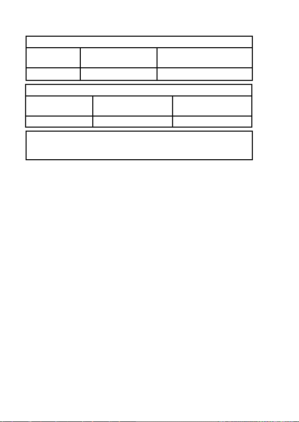
General values
Input type Absolute
accuracy Temperature
coefficient
All ≤±0.1% of span ≤±0.01% of span / °C
Basic values
Input type Basic
accuracy Temperature
coefficient
mA ≤±16 µA ≤±1.6 µA / °C
EMC immunity influence ..................................... < ±0.5% of span
Extended EMC immunity:
NAMUR NE 21, A criterion, burst ....................... < ±1% of span
CONTENTS

9106 - Product Version 9106-001 11
2-wire 4...20 mA output:
Signal range (span)...................................... 3.5...23 mA
Load stabillity .............................................. ≤ 0.01% of span / 100 Ω
Load resistance........................................... ≤(Vsupply -3.5) / 0.023 A [Ω]
Max. external 2-wire supply........................ 26 VDC
Effect of external 2-wire supply
voltage change............................................ < 0.005% of span / V
Relay output:
Status relay:
Relay function.............................................. ON / OFF
Programmable low setpoint ........................ 0...29.9 mA
Programmable high setpoint....................... 0...29.9 mA
Hysteresis for setpoints............................... 0.1 mA
Status relay in safe area:
Max. voltage................................................ 125 VAC / 110 VDC
Max. current ................................................ 0.5 AAC / 0.3 ADC
Max. AC power ........................................... 62.5 VA / 32 W
Marine approval:
Det Norske Veritas, Ships & Offshore ......... Pending
GOST R approval:
VNIIFTRI, Cert No........................................ See www.prelectronics.com
SIL certification:
exida, Cert No. ............................................ Pending
Observed authority requirements: Standard:
EMC 2004/108/EC ...................................... EN 61326-1
LVD 2006/95/EC.......................................... EN 61010-1
ATEX 94/9/EC.............................................. EN 60079-0, -11, -15 , -26
and EN 61241-0, -11
IECEx........................................................... IEC 60079-0, -11, -15 and -26
IEC 61241-0 and -11
c FM us ....................................................... FM 3600, 3611, 3810
CSA E60079-0, -15
CSA 22.2 -25, -142, -213
ANSI/ISA-12.00.01 / 12.12.02
UL, Standard for Safety .............................. UL 61010-1
*SIL .............................................................. *IEC61508
*=Pending
CONTENTS

12 9106 - Product Version 9106-001
Visualisation in 4501 of hardware / software error
Readout at hardware error
Error search Readout Cause
Communications test 4501 / 9106 NO.CO Connection error
EEprom error - check configuration FL.ER
Configuration error or crc
mismatch, recovery
configuration is loaded
User error II ! /
II !Loop limit exceeded
User error II ! /
II !Loop error
EEprom error - check configuration EE.ER /
IE.ER
Invalid configuration
(CRC or data)
Hardware error SU.ER Supply error
Hardware error RA.ER RAM error
Hardware error FL.ERIFlash error
Hardware error IN.ER Initialisation error
Hardware error C1.ER Hardware error - channel 1
Hardware error C2.ER Hardware error - channel 2
Hardware error DE.ER General error
! All error indications in the display flash once per second. The help text explains the error. In case
of cable fault the backlight also flashes. This can be reset by pressing the 3key.
Errors affecting both channels are shown as error on channel 1 - and the line showing channel 2 is
blank.
Hardware error can be reset in two ways. Either step through the menus (if the other channel is to
stay in operation) or power cycle the device.
CONTENTS

9106 - Product Version 9106-001 13
CONNECTIONS
33
31
COMMUNICATION FOUNDATION
41 / 51
42 / 52
43 / 53
44 / 54
COMMUNICATION FOUNDATION
41 / 51
42 / 52
43 / 53
44 / 54
COMMUNICATION FOUNDATION
12 / 14
11 / 13
12 / 14
11 / 13
250 Ω
Tx
250 Ω
COMMUNICATION FOUNDATION
Supply:
Outputs:
Inputs:
Active
Input
Passive
Input
DCS / PLC
DCS / PLC
Current
Active
output
Passive
output
Input
Output
2-wire transmitter
24 VAC &
24 VDC
Connections are identical
for channel 1 and channel 2.
Input
Output
CONTENTS

12
50.0
16.0mA
@C 31
14
12
11
NC*NC*
9106
32
+24V
34
33
44
43
42
41
54
53
52
51
13
+
-
Tx
CPU
FLASH
4...20 mA
4...20 mA
+
-
+
-
+
-
I+
mA
mA
+
-
I+
mA
mA
+
+
+
-
Tx
14 9106 - Product Version 9106-001
BLOCK DIAGRAM
Gnd.
Status relay N.C.
Status relay N.C.
Supply -
Power Rail connections
Supply +24 VDC
2-wire transmitter
2-wire transmitter
Channel 1
Channel 2
2-wire supply
2-wire supply
Supply, Green
Ch. 1 status, Red
Ch. 2 status, Red
Gnd.
Gnd.
CONTENTS

9106 - Product Version 9106-001 15
Signal error indications without display front
List of LED and error signal indications
Condition Green
LED
Ch. 1:
Red
Ch. 2:
Red
Status relay,
N.C.
Power rail
signal status
Device OK Blinking OFF OFF Energized OFF
No supply OFF OFF OFF De-energized ON
Device defective Blinking ON ON De-energized ON
Ch. 1 defective (ch. 2 OK) Blinking ON OFF De-energized ON
Ch. 2 defective (ch. 1 OK) Blinking OFF ON De-energized ON
Channel 1, signal OK Blinking OFF OFF Energized OFF
Ch. 1, signal limit exceeded Blinking Blinking OFF De-energized ON (if activated)
Ch. 1, fixed loop break limit
exceeded Blinking Flashing OFF De-energized ON
(if activated)
Channel 2, signal OK Blinking OFF OFF Energized OFF
Ch. 2, signal limit exceeded Blinking OFF Blinking De-energized ON (if activated)
Ch. 2, fixed loop break limit
exceeded Blinking OFF Flashing De-energized ON
(if activated)
Blinking : 50% ON and 50% OFF
Flashing : 8% ON and 92% OFF
CONTENTS

16 9106 - Product Version 9106-001
CONFIGURATION /
OPERATING THE FUNCTION KEYS
Documentation for routing diagram.
In general
When configuring the 9106, you will be guided through all parameters and you
can choose the settings which fit the application. For each menu there is a
scrolling help text which is automatically shown in line 3 on the display.
Configuration is carried out by use of the 3 function keys:
1 will increase the numerical value or choose the next parameter
2will decrease the numerical value or choose the previous parameter
3will save the chosen value and proceed to the next menu
When configuration is completed, the display will return to the default state
1.0. Pressing and holding 3will return to the previous menu or return to the
default state (1.0) without saving the changed values or parameters.
If no key is activated for 1 minute, the display will return to the default state
(1.0) without saving the changed values or parameters.
Further explanations
Password protection: Programming access can be blocked by assigning a
password. The password is saved in the device in order to ensure a high
degree of protection against unauthorised modifications to the configuration.
Default password 2008 allows access to all configuration menus.
Loop limits
In the menus LO.LIM and HI.LIM you can choose the current values which will
trigger a loop error alarm from the status relay. The NAMUR NE43 limits are
selected by setting LO.LIM at 3.6 mA and HI.LIM at 21 mA. The selected
limits are identical for both channels. This function can be deactivated by
selecting limits outside the range 3.5...23 mA. Alternatively, the status relay
can be used as a simple limit switch in the 1-channel version.
Theloopbreaklimitisfixed<=1mA.Ifthislimitisexceeded,thestatusrelay
will be de-energized.
CONTENTS

9106 - Product Version 9106-001 17
Signal and sensor error indication via display front 4501
Sensor error (loop break) is shown in line 1 on the display by flashing and .
The actual mA value is also shown followed by an explanatory text. Channel
1 is shown in line 2 and channel 2 is shown in line 3 on the display.
Line 4 on the display shows the condition of the COM (flashing bullet) indicating
correct functioning of 4501.
Advanced functions
The unit gives access to a number of advanced functions which can be reached
by answering “Yes” to the point “adv.set”.
Display setup: Here you can adjust the brightness contrast and the backlight.
Setup of tag numbers with 5 alphanumerics. Selection of functional readout
in line 2 and 3 on the display - choose between readout of loop current or
tag no. When selecting ”ALT” the readout toggles between loop current and
tag no.
Password: Here you can choose a password between 0000 and 9999 in order
to protect the unit against unauthorised modifications to the configuration.
The unit is delivered default without password.
Language: In the menu ”LANG” you can choose between 7 different language
versions of help texts that will appear in the menu. You can choose between
UK, DE, FR, IT, ES, SE and DK.
Power rail: In the menu ”RAIL” you can choose if a signal is transmitted to the
central surveillance in the PR 9410 power control unit when the signal limits
are exceeded..
*Safety Integrity Level (SIL): See Safety Manual for details.
CONTENTS

0000
PASSW.
Txt 1
33
0000
9999
1 2
NO
ADV.SET
Txt 2
NO
YES
1 2
3YES
LO.LIM1
Txt 3
0,0
29,9
1 2
3YES
HI.LIM1
Txt 4
0,0
29,9
1 2
YES
ADV.SET
Txt 2
3
1.1 1.2 1.2
3YES
HI.LIM2
Txt 4
0,0
29,9
1 2
3
1.2
3YES
LO.LIM2
Txt 3
0,0
29,9
1 2
1.2
12.2 ¤
20.0 ¤
1.0
18 9106 - Product Version 9106-001
1.0=Defaultstate.
Line 1 shows status for channel 1 and channel 2
Line 2 shows analogue value or tag no. for
channel 1. If the loop limit is exceeded (LO.LIM
and HI.LIM) the analogue value is shown for 5
sec. followed by txt 18. In case of loop break, 0.0
is shown for 5 sec. followed by txt 19.
Line 3 shows the same as line 2, only for
channel 2.
Line 4 shows status for relay and communication.
1.1=Onlyifpassword-protected.
1.2=Loopcurrentlimits(identicalforboth
channels) can be deactivated by
selecting values outside the range
3.5...23 mA.
Line 1 symbols:
=OK.Flashing=error.
Continued on the page
Routing diagram ADV.SET
ROUTING DIAGRAM
If no key is activated for 1 minute, the display will return to the default state
1.0 without saving configuration changes.
1Increase value / choose next parameter
2Decrease value / choose previous parameter
3Save the chosen value and proceed to the next menu
Hold 3Back to previous menu / return to menu 1.0 without saving
Power up
To default state 1.0
CONTENTS
This manual suits for next models
2
Table of contents
Other PR Repeater manuals


