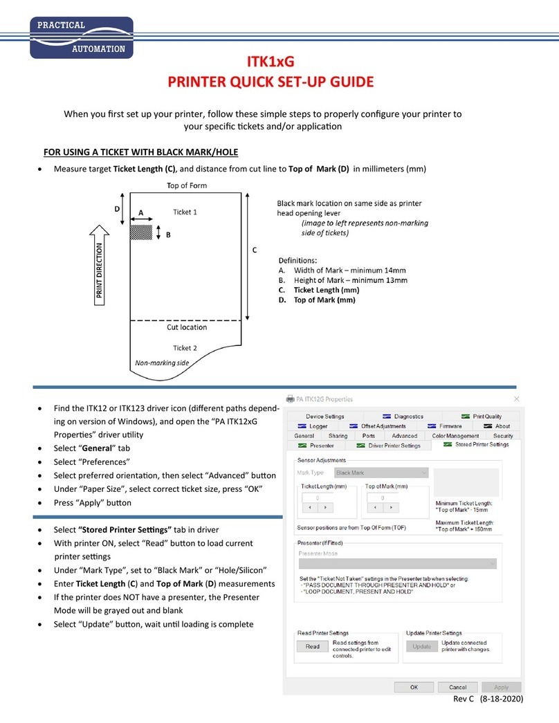
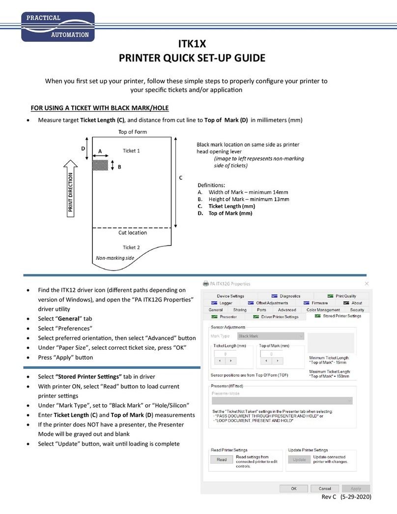
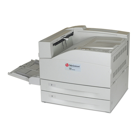
Practical Automation ITX 3000 series User manual

ITX 3000/2000 Printer User Manual (UMITX315.PDF)
Page 1 of 82 Date: 4/27/05
ITX 3000/2000
Printer Series
User’s Manual
PRACTICAL AUTOMATION INC.

ITX 3000/2000 Printer User Manual (UMITX315.PDF)
Page 2 of 82 Date: 4/27/05
TABLE of CONTENTS
1HOW TO CONTACT US.................................................................................................................................................... 6
1.1 LIMITED PRODUCT WARRANTY................................................................................................................................6
1.1.1 Warranty Terms...................................................................................................................................................... 6
1.1.2 Warranty Procedure................................................................................................................................................ 6
1.2 FCC NOTIFICATION .................................................................................................................................................... 7
1.3 REGULATORY COMPLIANCES ................................................................................................................................... 7
2ITX 3000/2000 OVERVIEW ............................................................................................................................................... 8
2.1 Introduction.................................................................................................................................................................... 8
2.2 Product Description........................................................................................................................................................ 8
2.3 Choosing FGL Emulation or Raster Graphics Mode..................................................................................................... 9
2.3.1 Programmer’s Notes:.............................................................................................................................................. 9
2.3.2 Managing Barcodes ................................................................................................................................................ 9
2.3.3 Detailed Printer Data ............................................................................................................................................ 10
2.4 MODEL NUMBERING SYSTEM ................................................................................................................................. 11
2.4.1 ITX Printer Model Numbers:................................................................................................................................11
2.4.2 ITX Power Supply Model Number....................................................................................................................... 12
2.4.3 Example of an ITX 2000 and 3000 Printer Model Number.................................................................................. 12
2.4.4 ITX Power Supply Options................................................................................................................................... 12
2.4.5 ITX Separate Component Model Numbers .......................................................................................................... 13
3PREPARATION FOR USE............................................................................................................................................... 14
3.1 Unpacking and Inspection ............................................................................................................................................ 14
3.2 Installation Location..................................................................................................................................................... 14
3.3 Power Connection ........................................................................................................................................................ 14
3.4 Data I/O Interface Connection ..................................................................................................................................... 14
3.4.1 Data I/O Interface Connection – Parallel IEEE-1284........................................................................................... 14
3.4.2 Data I/O Interface Connection – Serial RS232..................................................................................................... 14
3.4.3 Data I/O Interface Connection – USB 2.0 Full Speed.......................................................................................... 14
3.5 Adjustable Width Ticket Printers – Models with “A” and “AS” Suffixes..................................................................... 15
3.6 Ticket Stock Supply....................................................................................................................................................... 15
3.7 Ticket Stock Loading..................................................................................................................................................... 15
3.8 Auto-Sizing.................................................................................................................................................................... 15
3.9 Test Print ...................................................................................................................................................................... 15
3.10 Printer Set-up Confirmation......................................................................................................................................... 15
3.10.1 Configuration Settings.......................................................................................................................................... 15
3.10.2 EEPROM Settings................................................................................................................................................ 15
3.10.3 Configuring the Printer’s Data Interface:.............................................................................................................. 15
3.10.4 Print Speed Selection............................................................................................................................................ 16
3.10.5 Is a Printer Driver Required?................................................................................................................................16
4OPERATOR CONTROLS and INDICATORS............................................................................................................... 17
4.1 Rear I/O Panel.............................................................................................................................................................. 17
4.1.1 Data Interface Module Details.............................................................................................................................. 17
4.2 Switch and Display Panel............................................................................................................................................. 18
4.3 Panel LED Indicators................................................................................................................................................... 18
4.3.1 Power/Paper.......................................................................................................................................................... 18
4.3.2 Ready.................................................................................................................................................................... 18
4.3.3 Attn/Err................................................................................................................................................................. 18
4.4 Panel Switches.............................................................................................................................................................. 19
4.5 Panel Switch Operations .............................................................................................................................................. 19
4.5.1 Offline Operations................................................................................................................................................ 19
4.5.2 Power-On Operations ........................................................................................................................................... 19
5PRINTER PROGRAMMABLE CONFIGURATION SETTINGS............................................................................... 23
5.1 Overview....................................................................................................................................................................... 23
5.1.1 Factory Settings .................................................................................................................................................... 23
5.1.2 Special Customization .......................................................................................................................................... 23

ITX 3000/2000 Printer User Manual (UMITX315.PDF)
Page 3 of 82 Date: 4/27/05
5.1.3 EEPROM Parameter Storage Memory................................................................................................................. 23
6PRINTER STATUS INFORMATION............................................................................................................................. 24
6.1 ITX Printer Status Overview......................................................................................................................................... 24
6.2 Operator Status............................................................................................................................................................. 24
6.3 Port Level Interface Status ........................................................................................................................................... 24
6.4 Reverse Channel Status - Printer Status Programmer’s Information for Windows ..................................................... 24
7DATA INTERFACE AND AUXILIARY I/O.................................................................................................................. 25
7.1 IEEE-1284 Parallel Interface Cable ............................................................................................................................ 25
7.1.1 Parallel Port Signaling.......................................................................................................................................... 25
7.1.2 Parallel Interface Cable Schematic....................................................................................................................... 25
7.1.3 Parallel Interface Cable Quality............................................................................................................................ 25
7.1.4 Parallel Interface Card Assembly ......................................................................................................................... 25
7.1.5 Parallel Interface Pin-out Table............................................................................................................................ 26
7.2 RS232 Serial Interface.................................................................................................................................................. 27
7.2.1 RS-232 Serial Interface Card Assembly............................................................................................................... 27
7.2.2 Serial DIP-Switch Settings ................................................................................................................................... 27
7.2.3 Serial Interface Pin-out......................................................................................................................................... 27
7.3 USB Interface ............................................................................................................................................................... 28
7.3.1 USB Interface Pin-out Table................................................................................................................................. 28
7.3.2 USB Interface Cable............................................................................................................................................. 28
7.4 Auxiliary I/O Connector ............................................................................................................................................... 28
8TICKET STOCK HANDLING OPTIONS...................................................................................................................... 29
8.1 Ticket Separation/Delivery Options.............................................................................................................................. 29
8.1.1 Cutter/Ejector or Tearbar – uITX Desktop Model................................................................................................ 29
8.1.2 Cutter/Stacker-Retainer or Tearbar – pITX Countertop Mountable Model.......................................................... 29
8.1.3 Cutter/Ejector - kITX Kiosk Mountable Model................................................................................................... 29
8.1.4 Cutter/Ejector - eITX Desktop Model (with Ticket Enclosure Cabinet) ............................................................. 29
8.2 Low Ticket Stock (Paper) Monitoring – Auxiliary Input Port ...................................................................................... 29
8.2.1 Low Ticket Stock (Paper) Host Status Information.............................................................................................. 29
8.2.2 Printer Reactions to the Low Ticket Stock (Paper) Condition.............................................................................. 29
8.2.3 Ticket Holder with Low Ticket Detection............................................................................................................ 30
9TICKET STOCK INFORMATION................................................................................................................................. 31
9.1 Ticket Stock Specifications............................................................................................................................................ 31
9.1.1 Form Type ............................................................................................................................................................ 31
9.1.2 Ticket Stock - Thermal Paper Types: ................................................................................................................... 31
9.1.3 Ticket Stock - Paper Converter Vendor List......................................................................................................... 31
9.1.4 Ticket Stock Drawing (ITX 2/3002/3Fixed & ITX 2/3004AS Adjustable Width “ AS” Suffix Models) ............ 33
9.1.5 Ticket Stock Drawing (ITX 2/3003A & ITX 2/3004A - Adjustable Width “A” Suffix Models)......................... 33
9.1.6 Ticket Stock Drawing – Common to all ITX Printer Models............................................................................... 34
9.1.7 Stock Width.......................................................................................................................................................... 34
9.1.8 Stock Thickness.................................................................................................................................................... 34
9.1.9 Perforations........................................................................................................................................................... 34
9.1.10 Registration Marks................................................................................................................................................ 34
9.1.11 Ticket Length........................................................................................................................................................ 35
9.1.12 Ticket Stock Pre-Printing Information.................................................................................................................. 35
9.1.13 Example 2.0"Length Ticket Drawing for Fixed Width and “AS” Adjustable Width printers ............................ 36
9.1.14 Example 5.5"Length Ticket Drawing for Fixed Width and “AS” Adjustable Width printers ............................ 36
9.2 Ticket Stock Thermal Response Characteristics........................................................................................................... 37
9.2.1 Print Activation Energy ........................................................................................................................................ 37
9.3 Ticket Position Optical Sensors.................................................................................................................................... 37
9.3.1 Sensor Location: ITX 2000/3000 – Fixed Width Models..................................................................................... 38
9.3.2 Sensor Location: ITX 2003A/2004A/3003A/3004A – Adjustable Width Models............................................... 38
9.3.3 Sensor Location: ITX 2004AS/3004AS – Adjustable Width Models .................................................................. 38
9.3.4 Sensor Position Adjustments ................................................................................................................................38
9.3.5 Cutting Behind the Perforation............................................................................................................................. 39
9.4 Ticket Form Length Determination .............................................................................................................................. 40
9.4.1 Printer Ticket Length Determination.................................................................................................................... 40
10 EEPROM PARAMETER STORAGE MEMORY...................................................................................................... 41
10.1 EEPROM Parameter Memory Overview...................................................................................................................... 41
10.2 EEPROM Change Menu Entry..................................................................................................................................... 41

ITX 3000/2000 Printer User Manual (UMITX315.PDF)
Page 4 of 82 Date: 4/27/05
10.2.1 EEPROM Change Menu Operation...................................................................................................................... 41
10.2.2 Active and Inactive Menu Line............................................................................................................................. 41
10.3 EEPROM Menu #1 Printout......................................................................................................................................... 42
10.3.1 EEPROM Menu #1 Parameters Definitions ......................................................................................................... 42
10.4 EEPROM Menu #2 Printout......................................................................................................................................... 44
10.4.1 EEPROM Menu #2 Parameters ............................................................................................................................ 44
10.5 EEPROM Menu #3 Parameters.................................................................................................................................... 45
10.6 Restoring Factory Default Settings............................................................................................................................... 46
11 ERROR CODES............................................................................................................................................................. 47
11.1 Annunciation – Flash/Beep........................................................................................................................................... 47
11.1.1 Sequence Length – Flash/Beep............................................................................................................................. 47
11.1.2 Weighted Positions............................................................................................................................................... 47
11.1.3 Counting ............................................................................................................................................................... 47
11.1.4 Example................................................................................................................................................................ 47
11.2 Error Code Table – Flash/Beep.................................................................................................................................... 48
11.2.1 Error Code Table Notes........................................................................................................................................ 48
11.2.2 Error Code Table Information .............................................................................................................................. 48
11.2.3 Error Code Computation....................................................................................................................................... 49
12 DIAGNOSTICS and MAINTENANCE ....................................................................................................................... 50
12.1 Diagnostic Entry........................................................................................................................................................... 50
12.2 Diagnostic Sub Menu.................................................................................................................................................... 50
12.2.1 Special Functions.................................................................................................................................................. 50
12.2.2 Burn-in and Cut Tests........................................................................................................................................... 51
12.2.3 [F3] – Serial Port Test........................................................................................................................................... 51
12.3 Hex Dump Mode Functions.......................................................................................................................................... 51
12.3.1 Hex Data Dump.................................................................................................................................................... 51
12.3.2 Data Rate Measurement Test................................................................................................................................51
12.4 Periodic Maintenance................................................................................................................................................... 51
12.4.1 Paper/Registration Mark Sensor Maintenance...................................................................................................... 51
12.4.2 Printhead Cleaning................................................................................................................................................ 53
13 POWER SUPPLY INFORMATION............................................................................................................................ 54
13.1 Power supply D.C. Output Cable ................................................................................................................................. 54
13.2 Power Management...................................................................................................................................................... 54
13.3 Power Supply Requirements......................................................................................................................................... 54
13.3.1 Power Supply Additional Requirements............................................................................................................... 54
14 OPERATOR RE-PROGRAMMING OF FLASH MEMORY - PROCEDURE ...................................................... 55
14.1 General......................................................................................................................................................................... 55
14.2 Requirements ................................................................................................................................................................ 55
14.3 Flash Re-Programming Process................................................................................................................................... 55
14.3.1 Entering the Flash Load Mode.............................................................................................................................. 55
14.3.2 Flash Data Loading............................................................................................................................................... 55
14.3.3 Flash Loading Completion.................................................................................................................................... 56
14.3.4 Flash Loading Time.............................................................................................................................................. 56
14.3.5 Warning ................................................................................................................................................................ 56
15 FGL APPLICATION PROGRAMMERS INFORMATION..................................................................................... 57
16 ITX FIRMWARE OPTIONS FOR WINDOWS ......................................................................................................... 58
16.1 ITX ‘G’ Version Firmware ........................................................................................................................................... 58
16.1.1 Windows ‘G’ Driver Selection Table ................................................................................................................... 58
16.2 ITX FGL Firmware Driver........................................................................................................................................... 59
16.2.1 Windows FGL Driver Selection Table ................................................................................................................. 59
16.3 Installing the Windows Driver...................................................................................................................................... 60
16.3.1 Interface Choices – G Version Firmware Printer.................................................................................................. 60
16.3.2 Interface Choices – FGL Version Firmware Printer............................................................................................. 60
16.3.3 Adaptive Print Speed (G-Only) ............................................................................................................................ 60
16.3.4 Printer Status Information..................................................................................................................................... 60
17 SPECIFICATIONS........................................................................................................................................................ 61
18 REPLACING AN ETX 2000 PRINTER WITH AN ITX 2000 PRINTER................................................................ 62
18.1 Interface: ...................................................................................................................................................................... 62
18.1.1 Selection: .............................................................................................................................................................. 62
18.1.2 Cables:.................................................................................................................................................................. 62

ITX 3000/2000 Printer User Manual (UMITX315.PDF)
Page 5 of 82 Date: 4/27/05
18.2 Power Supply:............................................................................................................................................................... 62
18.3 Physical Profile:........................................................................................................................................................... 63
18.3.1 Locked Internal Ticket supply:............................................................................................................................. 63
18.3.2 Desktop Printer:.................................................................................................................................................... 63
18.3.3 Countertop Mountable Printer:............................................................................................................................. 63
18.3.4 Kiosk Mountable Printer:...................................................................................................................................... 63
18.4 Printer Language: ........................................................................................................................................................ 63
18.5 Printer Driver:.............................................................................................................................................................. 63
18.6 Printer Status Monitoring:............................................................................................................................................ 63
18.7 Ticket Stock : ................................................................................................................................................................ 64
18.7.1 Thermal Coating:.................................................................................................................................................. 64
18.7.2 Registration Marks: .............................................................................................................................................. 64
18.8 Conversion Process Steps:............................................................................................................................................ 64
18.9 ITX. ETX 2000 to ITX 2000 Model Number and Part Number Cross Reference Table ............................................... 65
19 APPENDIX...................................................................................................................................................................... 67
19.1 IEEE 1284 Parallel A-B Cable Schematic.................................................................................................................... 67
19.2 ITX 3000/2000 Mechanical Drawings.......................................................................................................................... 68
19.2.1 Mechanical Detail Drawing: uITX Desktop Printer (2.00” and 3.25”)................................................................. 68
19.2.2 Mechanical Detail Drawing: uITX Desktop Printer (4.00” A and AS Models) ................................................... 68
19.2.3 Mechanical Detail Drawing: pITX Countertop Printer (2.00” and 3.25”)............................................................ 69
19.2.4 Mechanical Detail Drawing: pITX Countertop Printer (4.00” -AT Model) ......................................................... 69
19.2.5 Mechanical Detail Drawing: pITX Countertop Printer (4.00” –AST Model)....................................................... 70
19.2.6 Mechanical Detail Drawing: kITX Kiosk Printer (2.00” and 3.25”) .................................................................... 70
19.2.7 Mechanical Detail Drawing: kITX Kiosk Printer (2/3.25-AC Model) ................................................................. 71
19.2.8 Mechanical Detail Drawing: kITX Kiosk Printer (4.00 –AC Model)................................................................... 71
19.2.9 Mechanical Detail Drawing: kITX Kiosk Printer (4.00” –ASC Model)............................................................... 72
19.2.10 Mechanical Detail Drawing: eITX Desktop Printer (with ticket enclosure cabinet) ........................................ 72
19.2.11 Mechanical Detail Drawing: pITX Countertop cutout (2.00” and 3.25”)........................................................ 73
19.2.12 Mechanical Detail Drawing: pITX Countertop cutout (4.00” Model)............................................................. 73
19.2.13 Mechanical Detail Drawing: PS60-14 - ITX Power Supply............................................................................. 74
19.2.14 Mechanical Detail Drawing: PS60-H Mounting Bracket ................................................................................. 74
19.2.15 kITX Optional Bottom Mounting Plate (2.00” and 3.25”) ............................................................................... 75
19.2.16 kITX Optional Bottom Mounting Plate (4.00”)................................................................................................ 75
19.2.17 kITX Optional Side Mounting Rails................................................................................................................. 76
19.2.18 Output Ticket Baskets:...................................................................................................................................... 76
19.2.19 pETX to pITX Countertop Adapter Plate - Model ITX-APETX0................................................................... 77
19.2.20 Ticket Holder w/ Low Paper Sensor................................................................................................................. 77
19.3 Electrical Circuits......................................................................................................................................................... 78
19.3.1 Typical Output Driver Application Circuits ......................................................................................................... 78
19.4 Registration Mark Location/Sensor Position - MathCad Template (V1.01)................................................................. 79

ITX 3000/2000 Printer User Manual (UMITX315.PDF)
Page 6 of 82 Date: 4/27/05
1HOW TO CONTACT US.
PRACTICAL AUTOMATION INC.
The Alinabal Group of Companies
45 Woodmont Road
P.O. Box 3028
Milford, CT 06460
VOICE: (203) 882-5640
FAX: (203) 882-5648
EMAIL:pa@practicalautomation.com
INTERNET: http://www.practicalautomation.com
1.1 LIMITED PRODUCT WARRANTY
1.1.1 Warranty Terms
Practical Automation, Inc. warrants each new ITX series printer to be free from defects in materials and workmanship to the
original purchaser. Our responsibility is limited to repair or replacement of the printer and/or accessory or part thereof at our
option for a period of one year from the date of shipment.
This limited warranty does not extend to any defect, malfunction or failure caused by or resulting from improper service,
packing, maintenance or repair, abuse, neglect, accident, or any other cause beyond the control of Practical Automation, Inc. or
to any product whose serial number has been removed, altered, replaced or rendered illegible.
Except and to extent provided herein, Practical Automation, Inc. makes no warranty, either express or implied, including any
warranty of merchantability or fitness for a particular purpose.
Practical Automation, Inc. shall not be liable to the purchaser or to any other person or firm for any specified or consequential
damages of any kind which result from the use or misuse by any person or loss of profits or product resulting from any defect
or malfunction or failure of this product.
No person, agent, distributor, service facility or company is authorized to change, modify or amend the terms of this limited
warranty in any manner or fashion whatsoever.
1.1.2 Warranty Procedure.
If you cannot resolve your equipment problem, notify Practical Automation, giving the model and serial number of your
equipment. Describe your problem in detail.
Upon receipt of this information, Practical Automation will send you service information if the trouble is easily corrected. If the
trouble requires factory service, we will so advise and provide written return authorization. Loaner printers can usually (subject
to availability) be shipped within 24 hours during the work-week by Practical Automation. Customers are required to pay all
shipping charges.
Refer also to the Warranty Terms and Packaging and Shipping instructions before returning any equipment.

ITX 3000/2000 Printer User Manual (UMITX315.PDF)
Page 7 of 82 Date: 4/27/05
1.2 FCC NOTIFICATION
FOR USERS IN THE UNITED STATES
WARNING:
Changes or modifications to this unit not expressly approved by the party responsible for compliance could void the user's
authority to operate the equipment.
Note:
This equipment has been tested and found to comply with the limits for a Class A digital device, pursuant to Part 15 of the FCC
rules. These limits are designated to provide reasonable protection against harmful interference when the equipment is operated
in a commercial environment. This equipment generates, uses, and can radiate radio frequency energy and, if not installed and
used in accordance with the instruction manual, may cause harmful interference to radio communications. Operation of this
equipment in a residential area is likely to cause harmful interference in which case the user will be required to correct the
interference at his own expense.
Shielded cables must be used with this unit to insure compliance with the Class A FCC limits.
FOR USERS IN CANADA
------------------------------------------------------------------------------------------------------------------------------------
This Class [A] digital apparatus meets all requirements of the Canadian Interference-Causing Equipment Regulations.
------------------------------------------------------------------------------------------------------------------------------------
Cet appareil numerique de la classe [A] respecte toutes les exigences du Reglement sur le material brouilleur du Canada.
-----------------------------------------------------------------------------------------------------------------------------------
1.3 REGULATORY COMPLIANCES
CE Mark: Compliant
Safety: ANSI/UL 60950 3rd ED. CAN/CSA C22.2 NO. 60950-00
IEC/CENELEC STDS EN 60950: 1999
CB REPORT: IEC 60950 3rd ED.
EMI/EMC: FCC Class A
EN 55024:1998 and EN 55022 1998 Class A

ITX 3000/2000 Printer User Manual (UMITX315.PDF)
Page 8 of 82 Date: 4/27/05
2ITX 3000/2000 OVERVIEW
2.1 Introduction.
This instruction manual provides information for the ITX series printers and associated options. It provides installation,
operational, configuration programming, systems applications notes and maintenance information.
2.2 Product Description.
The ITX series printers are high-speed ticket printers designed for use in movie-theater and event ticketing applications. They
have many features designed to make ticket printing faster and more reliable. The ITX has been optimized to work from
character-based operating systems (Dos, Unix, Linux, Etc.), permitting any combination of graphics and fonts to be printed, or,
with the optional “G” version firmware and a printer driver, in the Windows operating system environment for fast WYSIWYG
printing. Refer to section (2.4.1) for specifying the printer’s firmware option that is desired.
The ITX series has both fixed and adjustable ticket width models available. All models use direct thermal imaging and have
been optimized to print on ticket stock with registration marks. The ITX fixed width models print on standard 2.00" (50.8 mm)
or 3.25" (82.6 mm) wide ticket stock. ITX adjustable width printers can accommodate ticket widths from 2.00" (30.8mm) to
4.00" (82.6mm). Designed for use in applications where fast printing is required, the ITX has features and options structured to
support unattended operation in a kiosk or similar environment. An optional low paper sensor can be mounted with the ticket
stock supply to signal the application when the ticket supply needs to be replenished.
The ITX 2000/3000 (203/300 DPI respectively) can be connected to the system using one of the following data interfaces:
Parallel IEEE-1284, Serial RS-232 or Full Speed USB 2.0 Interface. The interface cables are standard “off-the-shelf” cables.
The ITX delivers extensive status information over these interfaces. This status provides the OEM host system with
information such as: Low Paper, Out of Paper, Ticket Count, error conditions, etc. This status information permits the host
application to be tightly coupled to the ticket printing process.
An external 24V power module provides the input power for ITX series printers. This single supply 24V operation makes for
easier integration into an OEM system power distribution scheme. An additional benefit is a power management scheme that
budgets the printer's operation to a modest 60W average power allocation.
The printer and control electronics are mounted in a single chassis. Depending on the printer model it can be mounted into a
counter-top (e.g. movie theaters), stand-alone on a desktop, with a locking ticket cabinet for enclosing the ticket stock or in a
kiosk mountable configuration. The separate power supply module is connected to the printer through a 6 foot (1.8 meter)
shielded cable with a circular DIN connector. This modular packaging scheme is extremely convenient and suitable for
mounting into any OEM system.

ITX 3000/2000 Printer User Manual (UMITX315.PDF)
Page 9 of 82 Date: 4/27/05
2.3 Choosing FGL Emulation or Raster Graphics Mode
Depending on the firmware installed, PA ticket printers can operate one of in two modes: FGL Emulation or Raster
Graphic mode. In general, new Windows applications should use the Raster Graphic mode, which relies on the Windows GDI
(Graphic Data Interface) process to create the print information. This provides the most font flexibility and best graphic
rendering.
FGL mode relies on the internal printer fonts and barcode generators to create the ticket. FGL uses a wide range of
ASCII printer commands to select the fonts and enable the other features. PA also offers an FGL Windows Printer Driver,
however, its intended use is primarily for backward compatibility with legacy ETX 2000 applications that were operating with
its FGL Windows driver. The FGL Windows driver, when the host application selects and only uses the printer internal fonts
can be very efficient and responsive. However, in application circumstances where Windows WYSIWYG printing is the goal,
the printer’s FGL firmware and the FGL Windows Driver are a less efficient combination of resources than the “G” firmware
and its Windows driver.
Here are some reasons that might direct you to use the FGL Emulation mode:
-1- When using a command based operating system such as DOS or Unix. (Without the available resources, of a
graphical operating system, such as Windows, programmatic creation the printer raster graphical information can be very challenging).
-2- When using the Serial (RS-232) Interface (only supported by the FGL printer).
-3- If your Ticketing Application specifies an FGL printer (ex: ETX or ITX). Consult your ticketing software vendor for their
recommendation of the printer model to be used.
In most other Windows situations, the Raster Graphic mode is preferred. You should order the ITX printer with the ‘G’
suffix (ex: ITX-2003G). If you have purchased the incorrect model, it is possible to download the correct firmware into the
printer.
Refer to section 16 for information regarding the correct printer driver for your application.
2.3.1 Programmer’s Notes:
The choice of which printer mode to use can be based on many factors, as outlined above. However, the fundamental
choice for the programmer is the location of the programmer’s drawing surface. For FGL emulation it is within the printer and
manipulated using printer commands sent over the interface. For the Raster Graphic mode, the ticket is created using Windows
programming methods, and drawn by the Windows GDI process. The printer commands are abstracted from the programmer by
the Windows Printer Driver, which sends them directly to the printer. The GDI process treats everything as graphic objects,
including fonts. The rendering process yields a large amount of printer data, but the Raster firmware is optimized to process
this data very efficiently.
When using PA’s V2.0x Windows Printer Drivers all of the advanced spooler and status features are supported by both
modes (FGL or “G”).
2.3.2 Managing Barcodes
One of the best features of FGL printers is the ability to create barcodes, automatically, using ASCII printer
commands. The most common use of this is from a command line based OS such as DOS or UNIX. Some FGL-based
applications can create FGL barcodes, in a Windows environment, by sending the printer command strings, as text, formatted in
a printer font. This process is outside the Windows WYSIWYG process and thus can be difficult for some programmers to
integrate with other Windows-based fonts and graphics.
For Raster Graphic printers, several vendors have created DLL utilities that will generate a graphic image of the
barcode, which can be placed on the ticket the same way as any other image. This can be advantageous to the programmer who
needs the creative flexibility provided by Windows environment. This method also allows designers to include proprietary
barcode symbols, which may not be included in the FGL palette.
For example, this vendor provides the Windows tools needed to create 2-D barcodes (PDF-417):
http://www.bizfonts.com/pdf417/
Other vendors provide similar tools for a variety of barcodes.
2.3.3

ITX 3000/2000 Printer User Manual (UMITX315.PDF)
Page 10 of 82 Date: 4/27/05
Detailed Printer Data
The following is a brief explanation of the process by which the FGL or “G” printer forms the printed image of a
character.
In order to print a simple line of text, each the letter’s graphic image (its pixels) need to be converted into printer dots.
For FGL printer, which has 13 internal fonts, one of these fonts is selected by a command, followed by the test for the
letters to be printed, using that font. For example, to print the word “Text”, in FGL, you would send “<F1>Text”. The printer
has an internally stored image of the dot patterns, for each printer font, and it uses this to print the selected font.
For Raster Graphics, the font selection is made using Windows programming methods. For example, a small Arial font
could be selected for the printable string of “Text” (as in the example above). The Windows GDI, using the Windows Printer
Driver, would then render this character string (convert the each letter’s graphic image, its pixels, into printer dot image data,
and commands). This data would be passed, to the printer, over the interface. The image below shows the graphical data.
Dots: Data (hex)
***** * F8 00 08
* * 20 00 08
* ** * * **** 20 C8 9E
* * * * * * 21 25 08
* ***** * * 23 E2 08
* * * * * 21 05 08
* ** * * ** 20 C8 86
Thus “Text” is converted to 7 rows of 3 bytes each. In addition, the Raster language requires a command prefix of at
least 2 characters, so each line is at least 5 bytes. This results in 35 bytes from the Raster Graphic driver, whereas only 8 data
bytes are required with FGL. For larger fonts, the difference can be 100:1, or more.
The Windows Raster programming method allows the use of any Windows font or graphic without special commands.
To support this larger data payload the “G” version printer has its electronic hardware, firmware and driver organized to handle
this very efficiently. Both modes have similar throughput. Note also that its is possible to change the operating mode of the
printer by simply downloading the preferred firmware to the printer.

ITX 3000/2000 Printer User Manual (UMITX315.PDF)
Page 11 of 82 Date: 4/27/05
2.4 MODEL NUMBERING SYSTEM
2.4.1 ITX Printer Model Numbers:
_ ITX __ __ __ - __ __ - __
| | | | | | | |
e MN DD TW FW TS CN DI
e Enclosure: u = Desktop (19.2.1 and 19.2.2)
p= Countertop mountable (19.2.3, 19.2.4 and 19.2.5) (1)
k = Kiosk mountable (19.2.6, 19.2.8 and 19.2.9) (2)
e = Desktop with locking ticket cabinet (19.2.10) (3)
s= Special Configuration (Custom Ordered)
MN Model Number: ITX = Printer Series Model Number
DD Dot Density: 300 = 300 DPI Print resolution (11.8 Dots/mm)
200 = 203 DPI Print Resolution (8.0 Dots/mm)
TW Ticket Width: 2= 2.00" (50.8 mm) Ticket width (9.1.4)
3 = 3.25" (82.6 mm) Ticket width (9.1.4)
3A = 2.00"- 3.25" (50.8 – 82.6 mm) Adjustable width (9.1.5) (4)
4A = 2.00"- 4.00"
(50.8 – 101.6 mm) Adjustable width (9.1.5) (4)
4AS = 2.00"- 4.00"
(50.8 – 101.6 mm) Adjustable width (9.1.4) (5)
x= x.xx" Custom Ticket Paper widths (Custom Ordered)
FW Firmware: (blank) = Standard Firmware “emulates” Boca’s FGL Ticket
Programming Language
G= “G” Firmware for Windows® WYSIWYG function and
GTX2000/3000 emulation.
TS Ticket Separation: C = Cutter (pITX = w/Ticket Stacker ; u/e/k ITX = w/Ticket Ejector)
T= Tearbar
CN Configuration Number:(blank) = Note: This entry is normally blank.
For a specially ordered printer configuration the “s” prefix will
be used (sITX 3003) with a three digit configuration number.
-
DI Data Interface: (6) Parallel = IEEE-1284 Parallel Interface (7.1.4, 7.1.5 and 19.1)
Serial = Serial RS232 Interface (7.2.1 and 7.2.3) (7)
USB = USB 2.0 Full Speed Interface (See 7.3 and 7.3.1) (8)
Notes:
(1) – The pITX adjustable models (3A, 4A. 4AS) are only available in the tearbar versions.
(2) – The kITX models are not available in tearbar versions, at this time.
(3) – eITX is not available, at this time, in the adjustable 4.00” models (4A, 4AS).
(4) - The registration mark sensor is on the non-adjustable side of the printer (the right hand side, viewed from the front).
(5) - The registration mark sensor is on the adjustable side of the printer (the left hand side, viewed from the front).
(6) - The Interface name: Parallel, Serial or USB is stamped into the I/O Interface bracket and becomes the final suffix of the
product’s model number label.
(7) – The Serial RS232 Interface is only supported with FGL firmware.
(8) – The USB Interface is supported by “G” and FGL firmware. For, the “FGL”, however, it is only after firmware version
V1.19 (or later) is installed on the FGL printer. Both the “G” and FGL require their respective V2.xx Windows Printer
Driver to be installed on the host computer for USB support to be functional.

ITX 3000/2000 Printer User Manual (UMITX315.PDF)
Page 12 of 82 Date: 4/27/05
2.4.2 ITX Power Supply Model Number
PS60 -14 __
| | MN Model Number PS60-14 Power Supply Model Number
MN LC (60W External Desktop Power Supply) (19.2.13)
LC = Line Cord: (blank) = with US approved line cord
E = no line cord for Export applications
2.4.3 Example of an ITX 2000 and 3000 Printer Model Number
pITX 3003-C-Parallel with PS60-14
The above two model numbers specify a complete ITX 3003 printer configured with:
Countertop mount p
a 3.25” paper width ITX 3003
-
a cutter with Ticket Stacker (pITX) C
-
a parallel data interface Parallel
with
60 watt external desktop power supply with a line cord for the North American market PS60-14
2.4.4 ITX Power Supply Options
The ITX printer system should be ordered with the PS60-14 External 24V Desktop Power Supply. It can be optionally
purchased without a power supply. The customer must provide an equivalent power supply (13.3).

ITX 3000/2000 Printer User Manual (UMITX315.PDF)
Page 13 of 82 Date: 4/27/05
2.4.5 ITX Separate Component Model Numbers
Model Number: Description
POWER SUPPLY
PS60-14 Universal input (90-240 VAC, 47-63 Hz) External 24VDC 60W Desktop Power Supply supplied
with US 115V line cord (19.2.13).
PS60-14E Universal input (90-240 VAC, 47-63 Hz) External 24VDC 60W Desktop Power Supply supplied
without a US 115V line cord.
PS60-H Mounting bracket for the PS60-14 power supply (19.2.14)
TICKET HOLDERS
GTX-THLP-2 Fan fold ticket holder (8.2.3 and 19.2.20) for ticket stock up to 2.50" (63.5 mm) in width
and 6.25" (158.8 mm) in length. Includes a low paper sensor and a 6' auxiliary cable (ATX-AC8).
GTX-THLP-4 Fan fold ticket holder (8.2.3 and 19.2.20) for ticket stock up to 4.50" (114.3 mm) in width
and 6.25" (158.8 mm) in length. Includes a low paper sensor and a 6' auxiliary cable (ATX-AC8).
TICKET OUTPUT BASKETS
TB-B23 Ticket basket for collecting 2 or 3.25 inch wide tickets that have been printed and cut. This basket is
used on FIXED WIDTH eITX and uITX cutter/ejector models. A basket is included with all
printer models that require one. (See Section 19.2.18)
TB-B4A Ticket basket for collecting 2 to 4 inch wide tickets that have been printed and cut. This basket is
used on ADJUSTABLE (A and AS) eITX and uITX cutter/ejector models. A basket is
included with all printer models that requires one. (See Section 19.2.18)
CABLES
ATX-AC8 Auxiliary Cable, shielded, 8 conductors, with MINIDIN-8 connector, 6 foot (1.8m) length
AC8-18 Auxiliary Cable, shielded, 8 conductors, with MINIDIN-8 connector, 18" (0.45m) length.
ATX-PC36 Parallel IEEE-1284 A-B Interface Cable, 6 foot (1.8m) length.
ITX-SC09 Serial Interface Cable, DB9M/DB9F, 10 foot (3.0m) length.
CUSB-206 USB 2.0 A-B Cable, 6 foot (1.8m) length.
COUNTERTOP ADAPTER PLATE FOR pITX
ITX-APETX0 pETX to pITX adapter plate (See section 19.2.19) 2.00 and 3.25” only.
DATA INTERFACE MODULES
IM-P Parallel IEEE 1284 Data Interface Module (See section 7.1.4)
IM-S Serial RS-232 Data Interface Module (See section 7.2.1)
IM-U USB 2.0 Data Interface Module (See section 7.3)
kITX MOUNTING PLATES and MOUNTING RAILS
MP-2 2.00 and 3.25 Mounting Plate (See section 19.2.15)
MP-4 4.00 Mounting Plate (See section 19.2.16)
MR-2x Mounting Rails (See section 19.2.17) sold in pairs.

ITX 3000/2000 Printer User Manual (UMITX315.PDF)
Page 14 of 82 Date: 4/27/05
3PREPARATION FOR USE
3.1 Unpacking and Inspection
-a- Inspect the shipping container for any signs of damage. If any damage is noted, contact freight carrier and file a claim with
them.
-b- Carefully unpack the printer system.
-c- Inspect the printer system carefully.
-d- Check the received items to the packing list. If any discrepancies are noted, contact our Customer Service Department.
-e- Save the packing material for reuse in shipment of the printer system.
-f- Note the Printhead Lever is shipped in the up position to reduce wear on
the roller. Put the lever down prior to operating the Printer.
3.2 Installation Location
The uITX is designed to be used on a desktop, with the ticket stock entering at the rear of the printer. Take care not to tangle
the cables with the ticket stock. The eITX also sits on the desktop, with the tickets stored inside the lockable chassis. The pITX
is designed to mount in a counter top, with the ticket stock placed below the printer. Take care to dress the cables away from
the ticket stock. Refer to section 19.2 for the appropriate dimensional drawings. As with all electronic equipment, the ITX
printer should be installed in a clean and ventilated location, free of excess dust and/or heat.
3.3 Power Connection
Refer to section 4.1 for a drawing of the printer's rear panel.
-a- Insure that the power switch on the rear panel of the printer is in the off position.
-b- Connect the DC power output cable from the power supply to the power input connector on the rear panel of the printer.
-c- Connect the AC line cord to the IEC entrance connector on the power supply.
-d- Connect the AC line cord to the wall power outlet.
3.4 Data I/O Interface Connection
The ITX printer requires a shielded data cable to connect to the host computer. Refer to section 4.1 for a drawing of the printer's
rear panel.
3.4.1 Data I/O Interface Connection – Parallel IEEE-1284
The ITX printer requires a shielded IEEE-1284 A-B parallel cable to connect to the host computer. Refer to section 4.1.1 for a
drawing of the printer's rear panel.
-a- Connect the 36 pin connector end of the cable to the parallel input cable on the rear of the printer.
-b- Connect the 25 pin connector end of the cable to the parallel output port of the PC.
3.4.2 Data I/O Interface Connection – Serial RS232
The ITX printer requires a shielded RS-232 Serial cable to connect to the host computer. Refer to section 4.1.1 for a drawing of
the printer's rear panel.
-a- Before plugging in the cable, make sure dip switches are set to your needed configuration. Refer to section 7.2.2
for list of switch settings and drawing showing actual switches. Note that 3-wire cables (sometimes called null-
modem) must use XON/XOFF flow control.
-b- Connect the 9 pin male connector end of the cable to the serial input cable on the rear of the printer.
-c- Connect the 9 pin female connector end of the cable to the serial output port of the PC.
3.4.3 Data I/O Interface Connection – USB 2.0 Full Speed
The ITX printer requires a 4 pin, shielded, USB A/B 2.0 Certified Compliant Cable to connect to a USB Compatible Computer.
Refer to section 4.1.1 for a drawing of the printer's rear panel.
-a- Connect the 4 pin connector end of the cable to the USB input cable on the rear of the printer.
-b- Connect the 4 pin connector end of the cable to the USB output port of the PC.

ITX 3000/2000 Printer User Manual (UMITX315.PDF)
Page 15 of 82 Date: 4/27/05
3.5 Adjustable Width Ticket Printers – Models with “A” and “AS” Suffixes.
The adjustable width ticket printers have a detailed ticket width adjustment guide, posted on the Practical Automation WEB site
in the “Down Load Drivers and Files” area, in the ITX 2000/3000 area, under the “Technical Notes” sub-section.
http://www.practicalautomation.com/download.html
These ticket width adjustment step by step procedures include photos. These adjustment guides are to be used as the reference
for this adjustment procedure.
3.6 Ticket Stock Supply
The ITX has been optimized for registration marked ticket stock (0.0075” caliper). For the desktop models (uITX), the ticket
stock should be placed behind the printer enclosure. For the counter top models (pITX), the ticket stock should be placed
below the printer. For all ticket stock supplies the thermally active side of the ticket stock needs to be facing up. Registration
marks must be on the opposite side from the printing side. The ticket stock must be positioned to provide a smooth, well-
aligned path to the printer's entry guides. Refer to section 9.1 for information pertaining to the ticket stock supply.
3.7 Ticket Stock Loading
The printer will automatically load the ticket stock onto the drive roller of the printer. For auto-loading, the printhead lever,
located on front left side of the printer mechanism, must be closed (in the fully downward position). After applying power to
the printer a long beep will be sounded indicating the printer is ready to accept ticket stock. Feed the ticket stock into the rear
paper guide until the ticket stock is stopped by the print mechanism. After a short time, the ticket stock will be pulled into the
loaded position.
3.8 Auto-Sizing
After every power on, the printer will calibrate the registration mark sensors and measure the length of the tickets. If the printer
runs out of tickets and new ticket stock is loaded without cycling the power, this auto-sizing will also be done again.
3.9 Test Print
Once the ticket stock has been loaded successfully a test ticket should be printed to insure that everything is operating properly.
Pressing the SELECT/F0 switch will place the printer offline; the READY LED will go out. Then by pressing the TEST/F1
switch a test ticket will be printed. Refer to section 4.5 for detailed information on these switch operations.
3.10 Printer Set-up Confirmation
It is recommended that the System Status Report be printed immediately after installation (power up while pressing F0).
Review the settings and confirm that they match the needs of the application. Refer to section 5.1.
3.10.1 Configuration Settings
The printer is configured at the factory to support the installed options: printer width, form type, and paper cutter. To verify
these settings, refer to section 5.1.
3.10.2 EEPROM Settings
If any settings on the Systems Status Report are not set in accordance with the intended operation of the printer, (Refer to
section 10.1) and follow the procedure to change these settings in the EEPROM.
3.10.3 Configuring the Printer’s Data Interface:
Host PC: The appropriate set-up for the PC’s Interface: Parallel, Serial or USB should be done, as required, using the
information provided by the PC’s User’s Information.
Printer: For the Parallel or USB interfaces there are no printer set-up selections required. The Serial Interface requires that
selections be made for Baud Rate, Flow Control, etc. Note: that these printer selections need to match the setup on the host PC.
Refer to section 7.2.2 for Serial Interface settings.
3.10.4

ITX 3000/2000 Printer User Manual (UMITX315.PDF)
Page 16 of 82 Date: 4/27/05
Print Speed Selection
The factory default Print Speed is 6 IPS (300 DPI) or 8 IPS (203 DPI). This setting will work well with most good quality
ticket stock. If faster print speeds are required you will need to obtain a faster thermally responsive ticket stock (see section
9.1.2) and change the Print Energy Table from "Normal" to "Alternate" to increase the print speed. This setting will allow you
to print at 8 IPS (300 DPI) or 10 IPS (203 DPI). Refer to the EEPROM selection method in Section 4.5.2.7. The selected
Energy Level, Energy Table, and the resulting maximum Print Speed will be displayed on the printer’s F0 printer status report
ticket print-out.
3.10.5 Is a Printer Driver Required?
If you are using the ‘G’ firmware, you must install the Windows driver.
If you are using the FGL firmware, you may or may not need a driver, depending on your application and operating system.
Refer to section 2.3 for a summary of the advantages of each configuration. Refer to section 2.4.1 to determine the proper
model numbers. Go to the website to obtain the correct driver, if required, as indicated by this table: 16.
Practical Automation WEB site: http://www.practicalautomation.com/download.html

ITX 3000/2000 Printer User Manual (UMITX315.PDF)
Page 17 of 82 Date: 4/27/05
4OPERATOR CONTROLS and INDICATORS
4.1 Rear I/O Panel
The following items are located on the rear panel: the power switch, power input connector, auxiliary I/O cable connector and
the installed data interface connector module (Parallel shown). The power switch in combination with holding one or more of
the switch and display panel switches provides entry into special set-up menus or diagnostic programs. The Aux I/O socket is
for connecting a low-paper sensor from an external ticket stock supply.
4.1.1 Data Interface Module Details
Shown below are the 3 interface modules available for the ITX printers. Note: The RS232 Serial is NOT supported on the “G”
firmware printers. It is only for FGL firmware printers.
4.1.1a 4.1.1b 4.1.1c

ITX 3000/2000 Printer User Manual (UMITX315.PDF)
Page 18 of 82 Date: 4/27/05
4.2 Switch and Display Panel
The switch and display panel provides the operator with an interface to the printer. The display LEDs and beeper are used to
output relevant printer operational status and warnings. The switches provide a means to control the various printed output
menus and test functions.
4.3 Panel LED Indicators
4.3.1 Power/Paper
This green LED indicator provides the following printer status information:
-1- Sanity indication/Normal display = very short OFF blink approx. every 14 sec.
-2- Presence of DC power = ON or Flashing when power is on.
-3- Out of Paper = rapid ON/OFF 50% duty cycle flashing when out of paper.
-4- Low Paper = slow ON/OFF 50% duty cycle flashing when paper is low.
-5- Diagnostic testing modes = 10% ON and 90% OFF when in diagnostic mode.
4.3.2 Ready
This green LED indicator provides the following printer status information:
-1- System readiness for operation = ON system is ready to accept data; OFF not ready.
-2- Data flow = During the receipt of data, the LED will blink,
following the state of the Busy signal.
-3- Reverse channel status = While not printing, during an IEEE-1284, or USB, reverse channel
status acquisition event, this LED will blink, following the state of the
Busy signal.
4.3.3 Attn/Err
This amber LED indicator, in combination with the beeper, is a general-purpose enunciator for the operator. It provides the
following printer status information:
-1- Switch press annunciation = short flash/beep for each switch pressed
-2- System warnings = an attention flash/beep to alert the operator to load paper, etc.
-3- System error codes = a repeating sequential series of coded flash/beep signals.
-4- Normal display = OFF

ITX 3000/2000 Printer User Manual (UMITX315.PDF)
Page 19 of 82 Date: 4/27/05
4.4 Panel Switches
There are four momentary push button switches on the user panel. These are used for a variety of manual interactions with the
printer. Some of these are printing a test ticket, entering data into the printer parameter memory (EEPROM), and selecting
miscellaneous diagnostic operations.
The switches are labeled:
SELECT/F0 On/Off line Select / Function 0
TEST/F1 Test print / Function 1
LINE FEED/F2 Line feed / Function 2
FORM FEED/F3 Form feed / Function 3
4.5 Panel Switch Operations
The switch and display panel switches are used for two modes of operation. These are offline and power-on operations.
4.5.1 Offline Operations
When the printer is operating normally, and on-line, pressing the [SELECT/F0] switch manually takes the printer to an offline
state. NOTE: As a reminder to the operator the A/E LED and buzzer will produce a single flash/beep approximately every 14
seconds. When the system is offline the switches operate in accordance with the Offline Switch Operations Table shown below.
4.5.1.1 Offline Switch Operations Table
Switch Operation/Function Notes
SELECT/F0 Offline / Online toggle Offline enables functions below.
TEST/F1 Prints a test ticket. Prints a graphical test ticket.
LINE FEED/F2 Advance approximately 0.1" Simple paper movement.
FORM FEED/F3 Advances one form length. Length depends on the printer setup and form type.
F0 and F1 Force a Cut Only when a cutter is installed. The switches must
be released together.
4.5.2 Power-On Operations
These functions provide an additional level of diagnostic support tools. These functions are provided for service or technical
support personnel.
4.5.2.1 Power-On Operations Table
For this mode, one or more switches are pressed, and held, while applying power to the printer. The switch is held until a
flash/beep occurs. The lists of power-on operations are detailed below. Refer to section 4.5.2.4 for System Information Help
Report, which outlines each menu, listed below.
Switch Operation/Function Notes
SELECT/F0 Print status report. If held longer, prints help menus.
(Refer to section 4.5.2.4 "System Info Help Report").
TEST/F1 Enter diagnostics menu Refer to section 12.1
LINE FEED/F2 Not Used Possible future feature
FORM FEED/F3 Enter EEPROM change menu Refer to section 10.2
F0 and F1 Re-program Flash Memory. Refer to section 14.3
F0 and F2 Printhead cleaning. Refer to section 4.5.2.10
F2 and F3 Hex Dump Diagnostic Mode Refer to section 12.3
4.5.2.2 Printer System Information and Reports
Printer system status information is available through a number of printed reports. These are the System Status Report, System
Help Report, EEPROM Interactive Parameter Change Menu, and Diagnostic Support Menus.

ITX 3000/2000 Printer User Manual (UMITX315.PDF)
Page 20 of 82 Date: 4/27/05
4.5.2.3 System Status Report
This is a printed report, which contains much of the operational or stored parameter information for the system. It includes:
firmware version numbers, diagnostic pass/fail results, interface configuration status, print intensity control levels,
miscellaneous system control parameters and operational data. This report is printed by continuously holding the [F0] switch
while turning on the power and releasing the switch after them first beep. Note: The System status report below is from an FGL
firmware printer. The “G” firmware printer provides this same report, however, a few details are different.
******************************************
* SYSTEM STATUS REPORT *
******************************************
Practical Automation
ITX Ticket Printer
Hold F0 to print Help Menus
Operating Status:
PHTEMP 24C
EXSEN1 1.15
EXSEN2 0.49
LOWPAPERSEN 0.00
PHVOLTAGE 23.94
SYSVOLTAGE 23.82
CUTSEN 4.36
LOADSEN 4.75
SYSCS 3.34
PHCS 2.50
INTDETS 4.02
Sensor Calibration
Load Cut
White = 973 , 973
Thresh = 560 , 540
Black = 148 , 108
INTERNAL STATUS
Build : .073
= 0000 ABE5, 0008 0A21, 0000 0086, 0000 0004, 0000 104A
> 32, 00, 00, 00, 00, 00, 00, 00, 00, 00, 00, 00
A2D Detect = 8
AutoDetect PH Words: 40
User Flash = 130816
Checksum: 1B30
Boot sum: E67F
Practical Automation IT
X
High Speed Image Printer
Practical Automation
ITX Ticket Printer
Model: ITX-2003
Firmware Version: V1.03
Revision Date: (05/30/01)
Resolution DPI: 203
ALL SYSTEM TESTS PASSED
CONFIGURATION:
Output Type: CUTTER
Data Interface: PARALLEL
*ACK Signal NO ACK
Two Image Rams
Max Image Rows : 640
Max Image Columns : 6400
EEPROM SETTINGS
* Settings can be changed
Print Energy Settings
* Intensity 6
* Energy Tables: Alternate
Print Speed 10.00 IPS
Paper Settings
* Low Paper Mode STATUS Only
* Form Type Ctrl SET BY CONFIG
* Form Length Ctrl AUTO WITH BU
Form Type REG MARK
Measured Size 5.56
* Backup Control Enabled
* Beeper ON
* Status Selector SHORT
* Purge Spooler DISABLED
* Cutter Mode ENABLED
Col Offset: 16
Row Offset:16
This manual suits for next models
1
Table of contents
Other Practical Automation Printer manuals
