PRADA NARGESA MT150A User manual
BASKETS TOOLING
MT150A
INSTRUTIONS BOOK
PRADA NARGESA, S.L
Ctra. de Garrigàs a Sant Miquel s/n · 17476 Palau de Santa Eulàlia (Girona) Spain
Tel. +34 972568085 · [email protected] · www.nargesa.com

HANDLING BOOK FOR THE BASKETS TOOLING 1
I N D E X
1. DESCRIPTION ..................................................................................... 2
2. CHARACTERISTICS ............................................................................ 2
3. IDENTIFICATION OF THE TOOLING PARTS .................................. 2
4. ASSEMBLING ................................................................................... 3
4.1. Mechanizing of the fastening holes ......................................... 4
5. INSTRUCTIONS FOR USE ................................................................... 4
5.1. Manual Mode ............................................................................. 5
5.2. Automatic Mode ..................................................................... 6
6. MAINTENANCE ................................................................................... 7
7. LIST OF PARTS .................................................................................... 8

HANDLING BOOK FOR THE BASKETS TOOLING 2
1. DESCRIPTION
The Baskets Tooling, as its name indicates, will allow the user to make a forge design known as
“Basket”. It is a shape compound of a number of bars which may vary according to the design and
which is to be twisted and compressed making a scroll in the opposite direction to the first scrolling op-
eration.
2. CHARACTERISTICS
The maximum sizes the user will be able to twist by using the baskets tooling for the MT150 are four
(4) 10mm square bars together, whenever it comes to the base material as mild steel (45Kg/mm2). The
bars maximum length is 205mm.
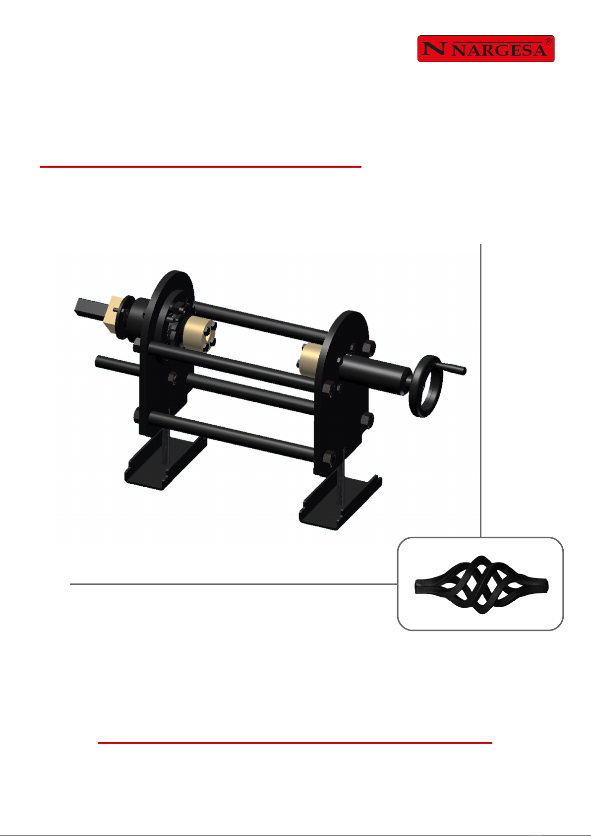
3. IDENTIFICATION OF THE TOOLING PARTS
Before proceeding with the assembling of the tooling pieces in the twisting machine MT150 we’ll identify
the most important parts of it so we can later on do a correct mounting and a proper further use.
As we can see in Picture 1 the parts will be identified as follows:
1 Main Drive Axis.
2 Traction square bar.
3 Fastening washer.
4 Manual traction.
5 Ratchet.
6 Driving groups.
7 Fastening screws for driving
groups.
8 Fixed axis
9 Fastening wheel.
10 Fastening wheel.
11 Front gauge.
Picture 1

HANDLING BOOK FOR THE BASKETS TOOLING 3
4. ASSEMBLING
To start up with the assembling the baskets tooling it is necessary to connect the MT150A/R to the line
tension and in the case of the MT150A it is required to make an initialisation as it explained on the ma-
chine handling book.
Once we have the machine started and with the initialisation made we then proceed to assemble the
tooling on the bench of the machine.
We place the traction square bar (2) on the head of the machine and we fasten it by using the fastening
washer (3), this will enable the user to make a steady and safe job since he doesn’t have to worry
about the traction square bar. In order to fasten the washer, it is necessary to use two screws provided
along with the tooling on the holes made in the head.
NOTE:
Then the baskets tooling must be moved to the head inserting the main drive axis (1) in the traction
square bar (2) if they are not symmetrically aligned then it is required to turn the main axis up to
achieve this. It is then when we make the main axis turn until the front gauge (11) reaches the ma-
chine structure and we fasten the tooling by using the nuts and the clamping parts (10).
4.1. Mechanizing of the fastening holes
Should the twisting machine does not have the holes to fix the fastening washer (3) the user will have
to mechanize them by following the process indicated below:
We’ll place the basket tooling as it is indicated in the previous section, once it is mounted in the trac-
tion square bar (2), we’ll put the fastening washer (3) in the Main drive Axis (1), we move the tooling
to the head and present the main drive axis (1) to the traction square bar (2), it is then when we put the
fastening washer (3) touching the head of the machine and being helped by a marker or some similar
so we can mark the holes centres. Then we dismantle the tooling and we make the holes by using a
drill so they can be screwed to M8 and with 15mm nut depth. Once this has been done we can go on
mounting the baskets tooling.
In case the twisting machine MT150 A/R doesn’t have those holes, the user will have to make them
by following the procedure exposed on section 4.1
HANDLING BOOK FOR THE BASKETS TOOLING 4
5. INSTRUCTIONS FOR USE
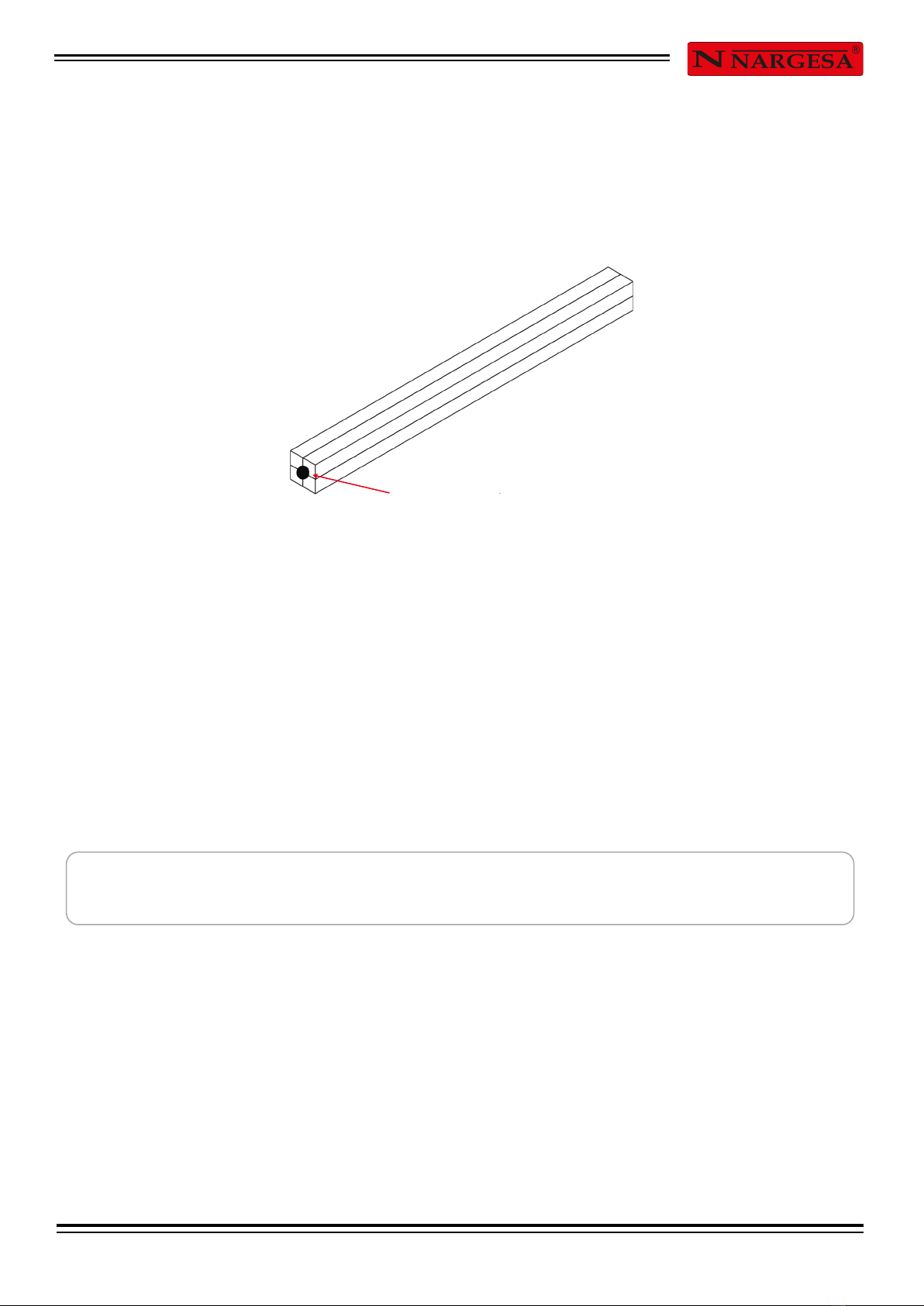
Before using the baskets tooling it will be necessary to prepare the material to work with. As we have
previously indicated in section 2, the maximum length of this material will be 205mm and it will be put
together until a bigger square bar is obtained (in case the user wants to make the basket with thin
square bars or four threads). In order to obtain this the bars must be welded on their extremes.
Once we have the material ready and the tooling set in the machine, we place the driving groups (6)
we need according to the bar we are going to use and we fasten them by using the Fastening screws
for the driving group(7). As a reference, the driving groups have some flat zones that enable us to
have them aligned. We mount one in the main driving (1) and the other one in the Fixed Axis (8) which
is driven by the wheel (9) located at the right of the tooling, if the driving groups(6) are not aligned, we
can make the machine drive turn to the right or to the left according to our needs, always bearing in
mind to be cautious to lift the ratchet (5) to release the screw.
Once we have the Driving groups aligned we’ll proceed to place the bars inside the Driving group cas-
ing (6) and we’ll make these bars fasten by using the Fastening wheel (9) we’ll make the bars to be
fixed between the Driving groups and then we’ll place the ratchet (5) back into its starting position .
WARNING:
Once we’re at this point we can make the baskets in two different ways: in Manual Mode or Automatic
Mode. Next we are going to explain both procedures.
Before inserting the bars inside the Driving group, it is necessary to grease the casing to ease up the
take out process.
Welding spot.

HANDLING BOOK FOR THE BASKETS TOOLING 5
5.1. Manual Mode
In order to make a basket in Manual Mode and get the references, first of all we ought to move the mil-
limetre scale on the head manually until it coincides the zero (0) with the central mark. To get this we
loose the pin from the millimetre scale and we make it turn with a hand. Then we fasten the pin again.
After this we make the drive turn the opposite direction to the ratchet (as it is indicated in picture 2, by
using the button on the control panel and we note that the bars are being twisted; we make the twisting
until approximately ¾ turn. Right after we make the drive turn in the opposite direction and we notice
the ratchet (5) locks the crown and makes the main driving axis (1) moves inside undoing the twist and
pressing the bars at the same time. We make this operation until the baskets obtain the size we desire.
Once the basket is finished we make a short torsion in the opposite direction aiming at taking out the
material from inside the driving groups (6). Finally we take off the bars by using the fastening wheel,
we also lift the ratchet (5) and with the help of the Manual traction (4) we bring back the Main driving
axis (1) to its original position.
Manual mode is commonly used for making a few baskets since for making a great number of them
and achieve them homogeneously it is more advisable to use the Automatic mode for achieving more.
Picture 2
HANDLING BOOK FOR THE BASKETS TOOLING 6
5.2. Automatic Mode
Automatic mode for manufacturing baskets is used when we want to make a mass and even produc-
tion of them. In order to make the programming we’ll carry out the following steps:
In case we have the machine automated, we’ll proceed to make the whole initialisation as it is
explained in its handling book.
We place the main driving axis (1) in the starting position, that is to say, completely displaced to-
wards the head of the machine and with the flat bar of the Driving group (6) in the upper part.
We press the PROGRAM key on the control panel.
It will appear a label on the screen reading “Starting Point”, since we already have the tooling in
its starting position it won’t be necessary to make any further action.
Press the PROGRAM key to confirm the starting point.
Press the “Square type of torsion” key on the Control Panel.
We make the torsion to the required direction, using the turning keys to twist the bars up to the
point we desire (Picture 2). There will appear two figures on the screen that will gradually in-
crease, indicating the final position of the torsion (¾ turn are son 90).
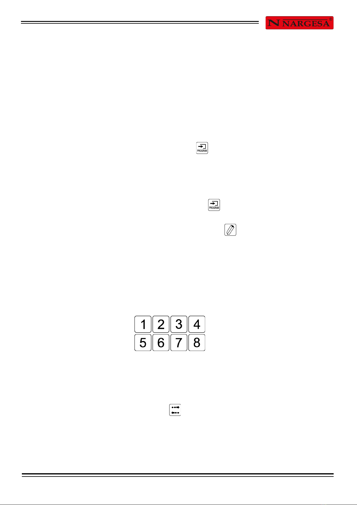
Once the desired position is reached we press one number key from 1 to 8 which will be the num-
ber of the program.
After that it will appear a label on the screen reading “Take out” it is then when we press the turn-
ing button towards the opposite direction to the one previously made until we reach a position
where the basket is completely shaped.
We press the key in order to fix that point
It is then when programming the basket has been concluded.

HANDLING BOOK FOR THE BASKETS TOOLING 7
We will have to make a series of small back and forth movements with the turning buttons to get
the material out of the driving groups (6).
With the help of the fastening wheel (9) we’ll get the fixed axis back (8) releasing the basket.
We lift the ratchet (5).
Press the number key where we have saved the basket program so the machine find automati-
cally the starting point for the torsion.
We take the main driving axis back up to its starting point by using the Manual traction (4).
We place a new set of bars, fix it with the fastening wheel and we already have the machine
about to start up a new basket as son as we press the number key where we had saved the op-
eration.
6. MAINTENANCE
The basket tooling has been designed and manufactured aiming at having an little maintenance tool-
ing, it will be enough just with a regular greasing of the screw and the main driving axis(1). It is ad-
visable that before each use the screw is cleaned, and right after using it should be greased as
well.
NOTE:
Grease in excess is harmful since it might be contaminated with an excess of dust.

HANDLING BOOK FOR THE BASKETS TOOLING 8
7. LIST OF PARTS

HANDLING BOOK FOR THE BASKETS TOOLING 9
1125-01-01-00219 ARANDELA EJE CABEZAL 1
2020-DIN934-M20 TUERCA DIN 934 M20 8
3020-DIN913-M6X12 ALLEN DIN 913 M6X12 1
4125-01-03-00215 TRACCION MANUAL 1
5020-DIN933-M12X60 TORNILLO HEXAGONAL DIN 933 M12X60 1
6020-DIN931-M12X45 TORNILLO HEXAGONAL DIN 931 M12X45 8.8 3
7125-01-01-00222 TAPA COJINETES 2
8030-CJ-32012-60X95X23 RODAMIENTO DE RODILLOS CONICOS 32012
Ø60xØ95x23 2
9125-01-01-00218 ARO PORTA COJINETE 1
10 131-01-01-00205 CONJUNTO PLACA DELANTERA 1
11 131-01-01-00208 ARO PORTA COJINETE EXTERIOR 1
12 125-01-01-00221 TRINQUETE 1
13 131-01-01-00200 CONJUNTO TUERCA 1
14 131-01-01-00212 CONJUNTO EJE TRACCION 1
15 131-01-01-00214 CONJUNTO TRACCION CUADRADO 5/16 PULGADA 2
16 131-01-01-00215 CONJUNTO TRACCION CUADRADO 3/8 PULGADA 2
17 131-01-01-00218 CONJUNTO TRACCION CUADRADO 1/4 PULGADA 2
18 020-DIN933-M12X30 TORNILLO HEXAGONAL DIN 933 M12X30 4
19 131-01-03-00200 CONJUNTO GUIA TRASERA 1
20 131-01-01-00206 CONJUNTO PLACA TRASERA 1
21 020-DIN933-M10X30 TORNILLO HEXAGONAL DIN 933 M10X30 4
22 020-DIN913-M6X10 ESPARRAGO DIN 913 M6X10 1
23 125-01-01-00224 VOLANTE ACCIONAMIENTO 1
24 125-01-01-00206 FIJACION INFERIOR 2
25 020-DIN934-M16 TUERCA DIN 934 M16 3
26 125-01-01-00204 VARILLA SEPARADORA 4
27 020-DIN912-M10X35 TORNILLO ALLEN DIN 912 M10 X35 1
28 125-01-01-00223 TOPE DELANTERO 1
29 020-DIN933-M8X20 TORNILLO HEXAGONAL DIN 933 M8X20 2
30 125-01-01-00228 ARRASTRE UTIL PIÑAS MT150 1
ELEMENTO Nº DESCRIPCION CANTIDAD
Table of contents
Other PRADA NARGESA Power Tools manuals

Popular Power Tools manuals by other brands

Speedwolf
Speedwolf SP-FS18 user manual

IQ Power Tools
IQ Power Tools iQPC912VSK installation guide

Sidchrome
Sidchrome SCMT26950 instruction manual

F.F. Group
F.F. Group GBC 540C PRO Original instructions

The Renovator
The Renovator Twist-A-Saw Deluxe Kit Safety and operating manual

Rothenberger
Rothenberger SUPERTRONIC 2000 Instructions for use


