Praim Neutrino Thin Client Series User manual
EN - Neutrino Dual Core
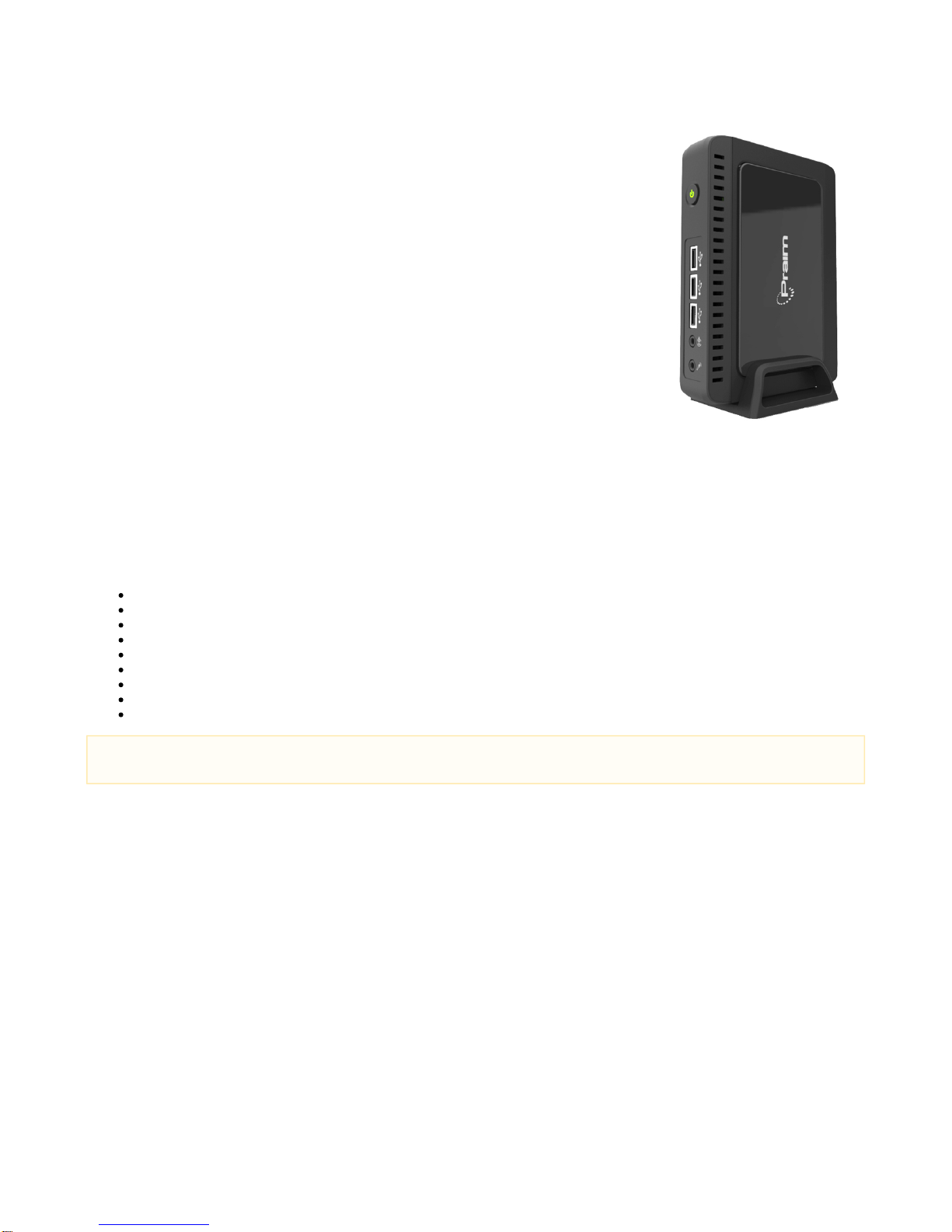
Neutrino Thin Client Series
Model Linux based Terminal - link to the User Guide N9052 ThinOX User Guide
Model Windows Embedded Standard 7 based Terminal - link to the User Guide N9072 Windows
Embedded 7 User Guide
Model Windows Embedded 10 IoT Terminal - link to the User Guide N9012 Windows 10 IoT User
Guide
Neutrino Zero Client Series
Modello PXE Boot TerminalN1002
Modello Linux based Terminal Citrix HDX - link to the User Guide N90-HDX ThinOX User Guide
Modello Linux based Terminal Microsoft RDP/RFX - link to the User Guide N90-RFX ThinOX User
Guide
Modello Linux based Terminal VMware Horizon - link to the User Guide N90-HOR ThinOX User
Guide
Unpacking the Terminal
Remove the terminal and all accessories from the packing carton.
Make sure you have the following components:
Installation Guide (this document)
Terminal logic unit
Stand foot for vertical installation
Screw for USB door + screw for stand foot
External power supply with power cord
DVI-I to VGA adapter
Optical mouse
Equipment Warranty Card
Safety instructions sheet
If you need help during installation, or if any items are missing or damaged, contact immediately your supplier.
Safety Notes
Do not expose the terminal, line cord, or monitor to rain or moisture. Do not place the terminal in direct sunlight, near heat sources or air
conditioners, or in dusty or dirty environments. Install the terminal as shown in this guide, do not allow anything to close in the ventilation
holes.
Warning - To prevent damages during the installation, make sure that the terminal is NOT connected to the electrical outlet and that the
display monitor is NOT powered on.
IMPORTANT - ThinMan administration software, utility tools and products
updates.
On the Praim WEB site are available all the products information on ThinMan: www.praim.com
The ThinMan User Guide is available at this link: https://wiki.praim.com/display/ThinMan/
We recommend the use of a pad for the mouse to work correctly.

Vertical installation of the terminal
The device is provided together with its stand foot.
Logic unit must be installed vertically as shown in the right figure.
For a better For a better stability the stand foot can be attached to
the bottom using the screw provided.
Installation on the back of LCD with
VESA bracket
The logic unit can be installed on the back of a LCD monitor using
the VESA bracket kit (option P/N 80EC00048).
This kit includes the standard VESA bracket. Please refer to the
specific installation guide for more information.
Pls check options list for the right cable.
Logic Unit
Front View Rear View
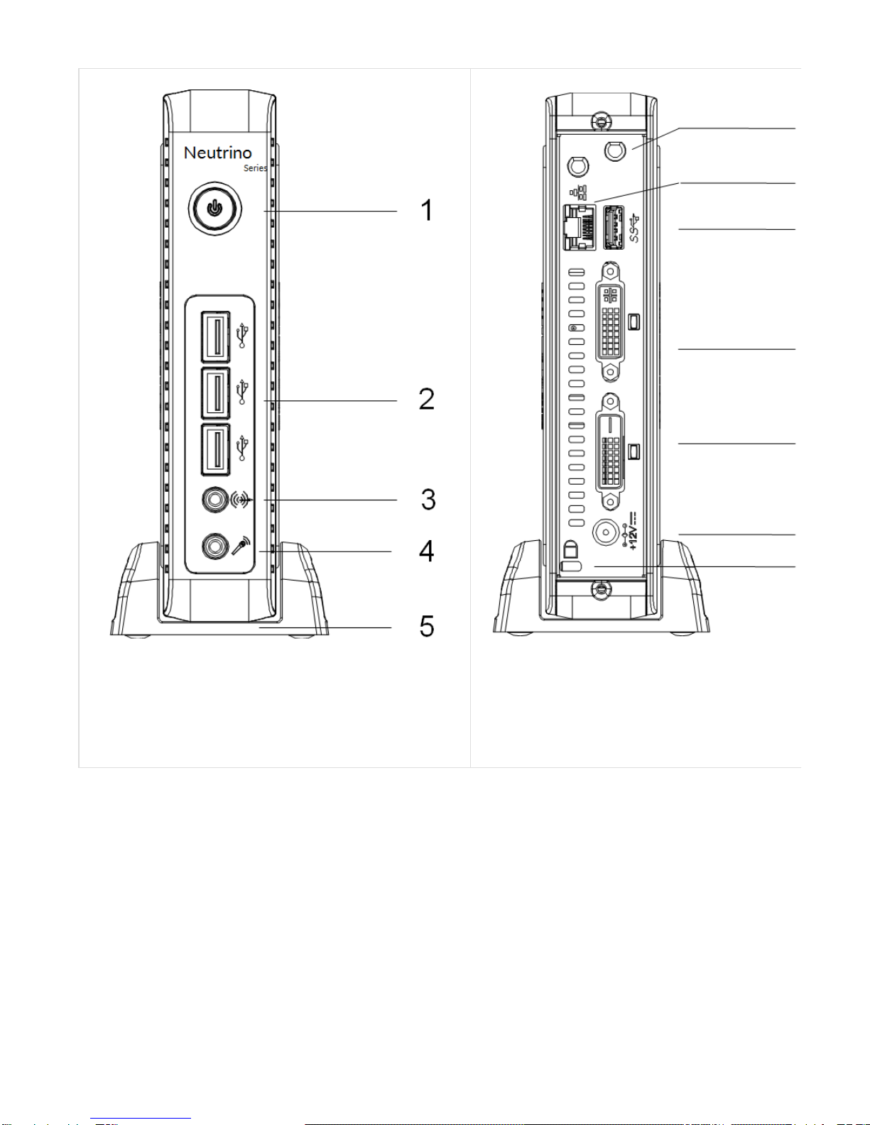
1. Power on/off button
2. USB 2.0 front ports
3. Audio line out
4. MIC input
5. Foot stand
6. External antenna holes
7. RJ45 (LAN) Connector
8. USB 3.0 rear port
9. DVI-I Video Connector
10. DVI-D Video Connector
11. 12V DC power supply connector
12. Kensington security lock
Connecting the Monitor (VGA or DVI)
Connect the DVI monitor to the primary display connector DVI-I (09) port on the back of the terminal. Using the DVI-VGA adapter it is possible
connect monitor with VGA (DB15) connector.
The second monitor must be connected to DVI-D (10) port on the back of the terminal.
Turn off the monitor before starting connections.
Connecting the LAN Cable
Connect the RJ45 Ethernet Cable to the LAN port (7) 10/100/1000Mbps Base-T Ethernet on the back of the terminal.

Connecting USB peripherals
USB peripherals can be connected both on front panel (2) and rear panel (8).
Blue color is for USB 3.0.
Connecting the External power adapter
Plug the connector of the external power supply into the connector (11).
Plug the power supply into a wall outlet. The power supply automatically senses 110 and 240 VAC power sources.
Powering ON your Terminal
The terminal logic unit has one power on button (1). To Power ON the terminal, push the Power On button. The power button assumes
GREEN light when the terminal is powered ON.
A few seconds after the unit was powered on, you will see on the video monitor the start up sequence of the terminal. Depending on the
configuration of the terminal, the sequence may take up to a minute to complete.
After this phase is completed, please follows the instructions shown on the display to complete the base configuration.
More information are available on the specific User Guide that depend from the terminal model (see at the start of this page).
Default User Name and Password (Case sensitive)
ThinOX WES7 WES8 Win10IoT
Administrator
User Name -- Admin Admin Admin
Password -- Admin Admin
User
User Name -- Admin User User
Password -- User User
Unit positioning
The unit should be placed in vertical position, except for the installation on the back of the monitor.
This document was produced by PRAIM.
Under no circumstances will PRAIM be liable for any damages, including incidental or consequential damages, expenses, lost profits or other
damages arising out of the use of or inability to use the product. The information contained in this manual is subject to change at any time
without notice. PRAIM shall not be liable for technical or editorial omissions made herein; nor for incidental or consequential damages
resulting from the furnishing, performance or use of this material. References in this manual to PRAIM products, programs and services does
not imply that PRAIM intends to make these available in all countries in which the product is marketed. References in this manual to third
party products, programs or services does not convey a commitment of any kind from PRAIM, nor does it imply that PRAIM intends to make
these available.
Company and/or product names are trademarks or registered trademarks of their respective owners.
The information disclosed in this publication is the property of PRAIM and is protected by copyright. All rights are reserved. No part of this
manual may be reproduced in any way or by any means without the prior written consent from PRAIM.

Declaration of conformity
CE - This product complies with the following protection requirements of EC Council directives:
2014/30/UE and subsequent changes;
2014/35/UE and subsequent changes.
Accordingly designed, it complies with the following harmonic rules:
EN 55022: 2010 AC:2011, EN 55024: 2010, EN 61000-3-2: 2014, EN 61000-3-3: 2013
EN60950-1:2006+A11:2009 +A1:2010 +A12:2012 +A2:2013
The symbol
indicates that the product is in conformance with the fundamental requirements, here above specified..
FCC rules
This equipment has been tested and found to comply with the limits for a Class B digital device, pursuant to Part 15 of the FCC rules. These
limits are designed to provide reasonable protection against harmful interference in a residential installation. This equipment generates, uses
and can radiate radio frequency energy and, if not installed and used in accordance with the instructions, may cause harmful interference to
radio communications. However, there is no guarantee that interference will not occur in a particular installation. If this equipment does cause
harmful interference to radio or television reception, which can be determined by turning the equipment off and on, the user is encouraged to
try to correct the interference by one or more of the following measures:
Reorient or relocate the receiving antenna.
Increase the separation between the equipment and receiver.
Connect the equipment into an outlet on a circuit different from that to which the receiver is connected.
Consult the dealer or an experienced radio/TV technician for help.
Shielded interface cables must be used in order to comply with emission limits.
Changes or modifications not expressly approved by the party responsible for compliance could void the user’s authority to operate the
equipment.
Power Management Settings
A key ENERGY STAR requirement for thin client products is power management features that significantly reduce energy consumption when
the product is not in use.
Power management allows a computer to automatically enter a low power sleep mode, after a defined period of inactivity.
The default power management setting have been selected for compliance with ENERGY STAR that are reccomended by the ENERGY
STAR program for optimal energy savings.
The power management features have been preset as follows :
Time to activate
display
sleep mode
Time to activate thin
client
sleep mode
Resuming from sleep mode
After 15 minutes of
user inactivity After 30 minutes of
user inactivity Product will exit sleep mode when the power/sleep button is pressed.
Product will exit display sleep mode with a simple input signal, like moving the mouse
or press any key on the keyboard.
If Wake On Lan is enabled, the system can resume from sleep in response to a
network signal.
For further information on energy management benefits please visit: orwww.energystar.gov www.eu-energystar.org

This manual suits for next models
8
Table of contents


