Clevo A110EU User manual

A110EU
SERVICE
MANUAL


Preface
I
Preface
LCD Computer
A110EU
Service Manual

Preface
II
Preface
Notice
The company reserves the right to revise this publication or to change its contents without notice. Information contained herein
is for reference only and does not constitute a commitment on the part of the manufacturer or any subsequent vendor. They
assume no responsibility or liability for any errors or inaccuracies that may appear in this publication nor are they in anyway
responsible for any loss or damage resulting from the use (or misuse) of this publication.
This publication and any accompanying software may not, in whole or in part, be reproduced, translated, transmitted or re-
duced to any machine readable form without prior consent from the vendor, manufacturer or creators of this publication, ex-
cept for copies kept by the user for backup purposes.
Brand and product names mentioned in this publication may or may not be copyrights and/or registered trademarks of their
respective companies. They are mentioned for identification purposes only and are not intended as an endorsement of that
product or its manufacturer.
Version 1.0
©September 2012
Trademarks
Intel, Celeron, and Intel Core are trademarks/registered trademarks of Intel Corporation.
Windows®is a registered trademark of Microsoft Corporation.
Other brand and product names are trademarks and/or registered trademarks of their respective companies.

Preface
III
Preface
About this Manual
This manual is intended for service personnel who have completed sufficient training to undertake the maintenance and
inspection of personal computers.
It is organized to allow you to look up basic information for servicing and/or upgrading components of the A110EU se-
ries LCD PC.
The following information is included:
Chapter 1, Introduction, provides general information about the location of system elements and their specifications.
Chapter 2, Disassembly, provides step-by-step instructions for disassembling parts and subsystems and how to upgrade
elements of the system.
Appendix A, Part Lists
Appendix B, Schematic Diagrams
Appendix C, Wall Moutning Information
Appendix D, Updating the FLASH ROM BIOS

Preface
IV
Preface
FCC Statement
(Federal Communications Commission)
You are cautioned that changes or modifications not expressly approved by the party responsible for compliance could void
the user's authority to operate the equipment.
This equipment has been tested and found to comply with the limits for a Class B digital device, pursuant to Part 15 of the
FCC Rules. These limits are designed to provide reasonable protection against harmful interference in a residential installa-
tion. This equipment generates, uses and can radiate radio frequency energy and, if not installed and used in accordance with
the instructions, may cause harmful interference to radio communications. However, there is no guarantee that interference
will not occur in a particular installation. If this equipment does cause harmful interference to radio or television reception,
which can be determined by turning the equipment off and on, the user is encouraged to try to correct the interference by one
or more of the following measures:
• Re orient or relocate the receiving antenna.
• Increase the separation between the equipment and receiver.
• Connect the equipment into an outlet on a circuit different from that to which the receiver is connected.
• Consult the service representative or an experienced radio/TV technician for help.
Operation is subject to the following two conditions:
1. This device may not cause interference.
And
2. This device must accept any interference, including interference that may cause undesired operation of the device.

Preface
V
Preface
FCC RF Radiation Exposure Statement:
1. This Transmitter must not be co-located or operating in conjunction with any other antenna or transmitter.
2. This equipment complies with FCC RF radiation exposure limits set forth for an uncontrolled environment. This equipment
should be installed and operated with a minimum distance of 20 centimeters between the radiator and your body.
IMPORTANT SAFETY INSTRUCTIONS
Follow basic safety precautions, including those listed below, to reduce the risk of fire, electric shock, and injury to persons
when using any electrical equipment:
1. Do not use this product near water, for example near a bath tub, wash bowl, kitchen sink or laundry tub, in a wet basement or
near a swimming pool.
2. Avoid using this equipment with a telephone line (other than a cordless type) during an electrical storm. There may be a
remote risk of electrical shock from lightning.
3. Do not use the telephone to report a gas leak in the vicinity of the leak.
4. Use only the power cord and batteries indicated in this manual. Do not dispose of batteries in a fire. They may explode. Check
with local codes for possible special disposal instructions.
5. This product is intended to be supplied by a Listed Power Unit (Full Range AC/DC Adapter – AC Input 100 - 240V, 50 - 60Hz,
DC Output 19V, 6.3A).
CAUTION
This Computer’s Optical Device is a Laser Class 1 Product
Warning
Use only shielded cables to connect I/O devices to this equipment. You are cautioned that changes or modifications not ex-
pressly approved by the manufacturer for compliance with the above standards could void your authority to operate the
equipment.

Preface
VI
Preface
Instructions for Care and Operation
The notebook computer is quite rugged, but it can be damaged. To prevent this, follow these suggestions:
1. Don’t drop it, or expose it to shock. If the computer falls, the case and the components could be damaged.
2. Keep it dry, and don’t overheat it. Keep the computer and power supply away from any kind of heating element. This
is an electrical appliance. If water or any other liquid gets into it, the computer could be badly damaged.
3. Follow the proper working procedures for the computer. Shut the computer down properly and don’t forget to save
your work. Remember to periodically save your data as data may be lost if the battery is depleted.
4. Avoid interference. Keep the computer away from high capacity transformers, electric motors, and other strong mag-
netic fields. These can hinder proper performance and damage your data.
5. Take care when using peripheral devices.
Power Safety
The computer has specific power requirements:
• Only use a power adapter approved for use with this computer.
• Your AC adapter may be designed for international travel but it still requires a steady, uninterrupted power supply. If you are
unsure of your local power specifications, consult your service representative or local power company.
• The power adapter may have either a 2-prong or a 3-prong grounded plug. The third prong is an important safety feature; do
not defeat its purpose. If you do not have access to a compatible outlet, have a qualified electrician install one.
• When you want to unplug the power cord, be sure to disconnect it by the plug head, not by its wire.
• Make sure the socket and any extension cord(s) you use can support the total current load of all the connected devices.
• Before cleaning the computer, make sure it is disconnected from any external power supplies.
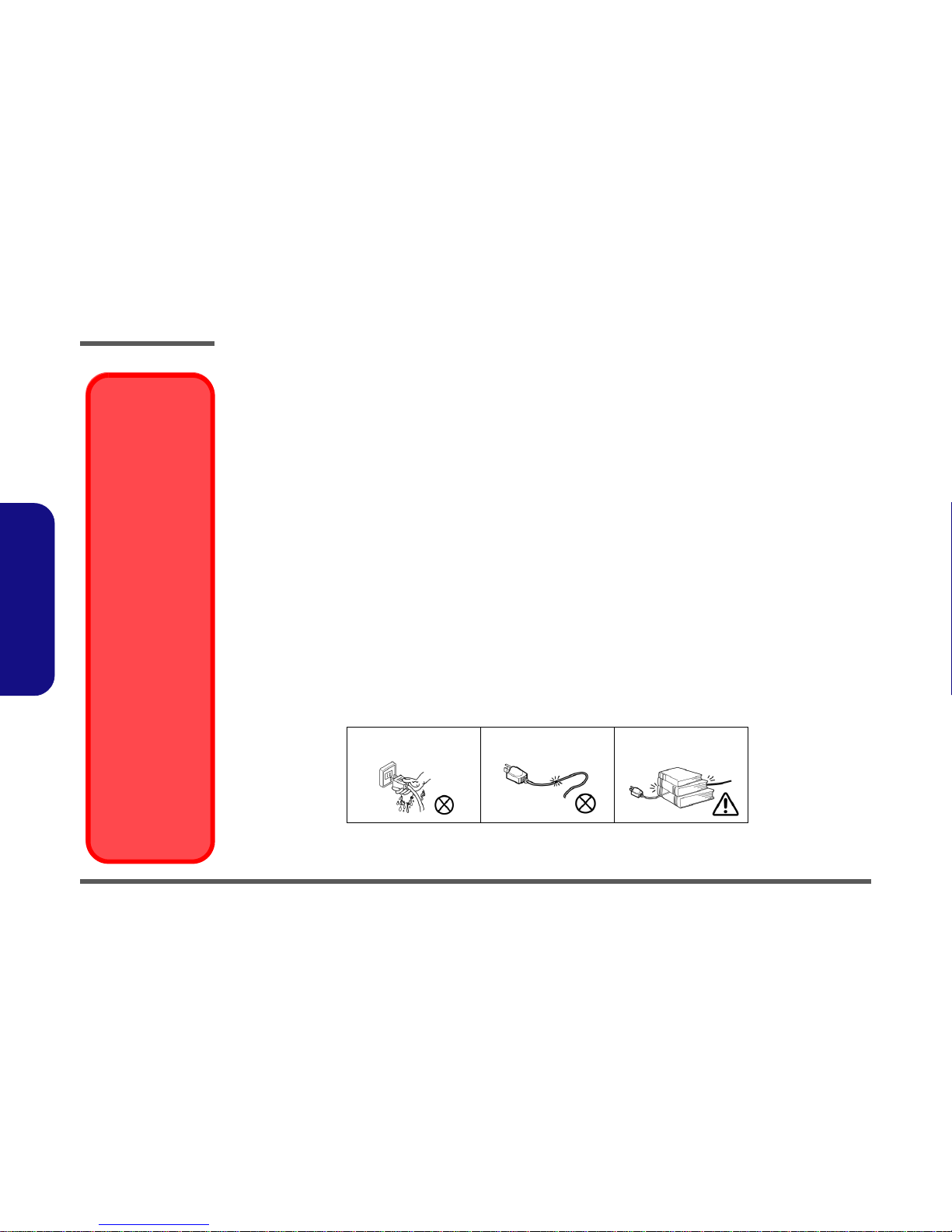
Do not plug in the power
cord if you are wet. Do not use the power cord if
it is broken. Do not place heavy objects
on the power cord.
Removal Warning
When removing any
cover(s) and screw(s)
for the purposes of de-
vice upgrade, remem-
ber to replace the
cover(s) and screw(s)
before restoring power
to the system.
Also note the following
when the cover is re-
moved:
• Hazardous mov-
ing parts.
• Keep away from
moving fan blades
Power Safety
Warning
Before you undertake
any upgrade proce-
dures, make sure that
you have turned off the
power, and discon-
nected all peripherals
and cables (including
telephone lines and
power cord). You must
also remove your bat-
tery in order to prevent
accidentally turning the
machine on.

Preface
VII
Preface
Cleaning
Do not apply cleaner directly to the computer, use a soft clean cloth.
Do not use volatile (petroleum distillates) or abrasive cleaners on any part of the computer.
Servicing
Do not attempt to service the computer yourself. Doing so may violate your warranty and expose you and the computer to
electric shock. Refer all servicing to authorized service personnel. Unplug the computer from the power supply. Then refer
servicing to qualified service personnel under any of the following conditions:
• When the power cord is damaged or frayed.
• If the computer has been exposed to any liquids.
• If the computer does not work normally when you follow the operating instructions.
• If the computer has been dropped or damaged (do not touch the poisonous liquid if the LCD panel breaks).
• If there is an unusual odor, heat or smoke coming from your computer.
Removal Warning
When removing any cover(s) and screw(s) for the purposes of device upgrade, remember to replace the cover(s) and
screw(s) before turning the computer on.

Preface
VIII
Preface
Related Documents
You may also need to consult the following manual for additional information:
User’s Manual on CD
This describes the computer’s features and the procedures for operating the computer and its ROM-based setup program.
It also describes the installation and operation of the utility programs provided with the computer.
System Startup
1. Remove all packing materials, CDs/DVDs and floppy disks etc.
2. Securely attach any peripherals you want to use with the computer
(e.g. keyboard and mouse) to their ports.
3. Attach the AC/DC adapter to the DC-In jack located at the rear of
the LCD, then plug the AC power cord into an outlet, and connect
the AC power cord to the AC/DC adapter.
4. Push the power button at the front of the computer (along the
bottom of the LCD) to turn the computer “on”.
Figure 1 -
Computer with AC/DC Adapter Plugged-In/Power Button
Power Button (located along the bottom of the LCD)

Preface
IX
Preface
Contents
Notice .............................................................................................1-II
About this Manual .........................................................................1-III
FCC Statement ..............................................................................1-IV
FCC RF Radiation Exposure Statement: ........................................1-V
Cleaning ...................................................................................... 1-VII
Servicing ...................................................................................... 1-VII
Introduction ..............................................1-1
Overview .........................................................................................1-1
Specifications ..................................................................................1-2
Tilting the LCD Screen & Adjusting the Height .............................1-4
External Locator - Front View ........................................................1-5
External Locator - Left & Right Side Views ...................................1-6
External Locator - Rear View .........................................................1-7
Mainboard Overview - Top (Key Parts) .........................................1-8
Mainboard Overview - Bottom (Key Parts) ....................................1-9
Mainboard Overview - Top (Connector) ......................................1-10
Mainboard Overview - Bottom (Connectors) ...............................1-11
Disassembly ...............................................2-1
Overview .........................................................................................2-1
Maintenance Tools ..........................................................................2-2
Connections .....................................................................................2-2
Maintenance Precautions .................................................................2-3
Disassembly Steps ...........................................................................2-4
Removing and Installing the Battery ...............................................2-5
Removing the Rear Top Cover ........................................................2-7
Removing the Hard Disk Drive .......................................................2-8
Hard Disk Upgrade Process ............................................................2-8
Removing the Optical (CD/DVD) Device ....................................2-13
Upgrading the System Memory (RAM) ........................................2-14
Removing the Stand ...................................................................... 2-16
Removing the Wireless LAN Module .......................................... 2-17
Removing the CPU ....................................................................... 2-18
Part Lists ..................................................A-1
Part List Illustration Location ........................................................ A-2
Front ............................................................................................... A-3
Front (No CCD) ............................................................................. A-4
MB ................................................................................................. A-5
Back ............................................................................................... A-6
HDD ............................................................................................... A-7
DVD ............................................................................................... A-8
Combo ............................................................................................ A-9
Schematic Diagrams.................................B-1
System Block Diagram ...................................................................B-2
Processor 1/7 ...................................................................................B-3
Processor 2/7 ...................................................................................B-4
Processor 3/7 ...................................................................................B-5
Processor 4/7 ...................................................................................B-6
Processor 5/7 ...................................................................................B-7
Processor 6/7 ...................................................................................B-8
Processor 7/7 ...................................................................................B-9
DDR3 SO-DIMM_0 .....................................................................B-10
DDR3 SO-DIMM_1 .....................................................................B-11
PCH PCI ......................................................................................B-12
PCH USB/PCIE/DMI ...................................................................B-13
PCH SATA ...................................................................................B-14
PCH GPIO/HDA ..........................................................................B-15
PCH NVRAM/HDMI ...................................................................B-16
PCH FDI/USB3/Clock ..................................................................B-17

Preface
X
Preface
PCH Power ...................................................................................B-18
PCH Power ...................................................................................B-19
PCH GND ....................................................................................B-20
LVDS, Inverter .............................................................................B-21
SCALAR ......................................................................................B-22
SCALAR-1 ...................................................................................B-23
HDMI IN, USB2.0*2 ................................................................... B-24
HDMI OUT .................................................................................. B-25
KBC-ITE IT8518 .........................................................................B-26
Audio Codec ALC269 ..................................................................B-27
AMP2607 & Audio Switch .......................................................... B-28
Card Reader / RTS5229 ...............................................................B-29
LAN (Intel LAN82579) ...............................................................B-30
LAN CON/New Card ...................................................................B-31
HDD/ODD/ESATA .....................................................................B-32
USB3.0 .........................................................................................B-33
WLAN/TPM1.2/CCD/TP ............................................................B-34
5VS, 3VS, 1.5VS_CPU, 12V .......................................................B-35
3.3V_M, 1.05V_M, 1.05VS_VTT ...............................................B-36
COM Port / PS2 ............................................................................B-37
VDD3, VDD5 ...............................................................................B-38
Power 0.925V/1.8VS ....................................................................B-39
Power 1.5V/1.05VS ......................................................................B-40
Power VCORE1 ...........................................................................B-41
Power VCORE2 ...........................................................................B-42
AC-In, Charger .............................................................................B-43
Audio/USB Board ........................................................................B-44
Power SW LED CIR Board .........................................................B-45
Power Sequence ...........................................................................B-46
Wall Mounting Guide............................. C-1
Removing the Stand ....................................................................... C-2
Mounting Systems ..........................................................................C-3
General Guidelines for Wall Mounting ..........................................C-4
Mounted System Example ..............................................................C-5
Updating the FLASH ROM BIOS .........D-1
Download the BIOS ....................................................................... D-1
Unzip the downloaded files to a bootable CD/DVD/ or
USB Flash drive ............................................................................. D-1
Set the computer to boot from the external drive .......................... D-1
Use the flash tools to update the BIOS .......................................... D-2
Restart the computer (booting from the HDD) .............................. D-2

Introduction
Overview 1 - 1
1.Introduction
Chapter 1: Introduction
Overview
This manual covers the information you need to service or upgrade the A110EU series LCD computer. Information about
operating the computer (e.g. getting started, and the Setup utility) is in the User’s Manual. Information about drivers (e.g.
VGA & audio) is also found in User’s Manual. That manual is shipped with the computer.
Operating systems (e.g. Windows 7, etc.) have their own manuals as do application software (e.g. word processing and
database programs). If you have questions about those programs, you should consult those manuals.
The A110EU series computer is designed to be upgradeable. See Disassembly 2 on page 2 - 1 for a detailed description
of the upgrade procedures for each specific component. Please note the warning and safety information indicated by the
“” symbol.
The balance of this chapter reviews the computer’s technical specifications and features.

Introduction
1 - 2 Specifications
1.Introduction
Specifications
Latest Specification Information
The specifications listed here are correct at the
time of sending them to the press. Certain items
(particularly processor types/speeds) may be
changed, delayed or updated due to the manu-
facturer's release schedule. Check with your
service center for more details.
CPU
The CPU is not a user serviceable part. Ac-
cessing the CPU in any way may violate your
warranty.
Processor Options
Intel® Core™ i7 Processor
i7-3770S (3.10GHz)
8MB L3 Cache, 22nm, DDR3-1600MHz, TDP 65W
i7-3570S (3.10GHz)
6MB L3 Cache, 22nm, DDR3-1600MHz, TDP 65W
Intel® Core™ i5 Processor
i5-3550S (3.00GHz), i5-3475S (2.90GHz), i5-3470S
(2.90GHz), i5-3450S (2.80GHz), i5-3570T (2.30GHz)
6MB L3 Cache, 22nm, DDR3-1600MHz, TDP 65W
Intel® Pentium® Processor
G640 (2.80GHz)
3MB L3 Cache, 22nm, DDR3-1066MHz, TDP 65W
Intel® Celeron® Processor
G540 (2.50GHz)
2MB L3 Cache, 22nm, DDR3-1066MHz, TDP 65W
Core Logic
Intel® HM61 Chipset
BIOS
One 48Mb SPI Flash ROM
AMI BIOS
Memory
Two 204 Pin SO-DIMM Sockets Supporting DDR3 1333/
1600MHz Memory
Memory Expandable up to 8GB
Storage
(Factory Option) One Changeable 12.7mm(h) Optical
Device Type Drive (Super Multi Drive Module or
Blu-Ray Combo Drive Module)
One Changeable 2.5" 9.5mm (h) SATA (Serial) HDD
One Changeable 3.5" 25mm (h) SATA (Serial) HDD
Video Adapter
Intel Integrated GPU
(GPU is Dependent on Processor)
Intel® HD Graphics
Dynamic Frequency (Intel Dynamic Video Memory Technol-
ogy for up to 1.7GB)
Microsoft DirectX®10 Compatible
Intel® HD Graphics 2500
Dynamic Frequency (Intel Dynamic Video Memory Technol-
ogy for up to 1.7GB)
Microsoft DirectX®11 Compatible
Intel® HD Graphics 4000
Dynamic Frequency (Intel Dynamic Video Memory Technol-
ogy for up to 1.7GB)
Microsoft DirectX®11 Compatible
LCD
21.5" (54,61cm) FHD
Audio
High Definition Audio Compliant Interface
Built-In Microphone
2 * Built-In Speakers
Security
BIOS Password
Security (Kensington® Type) Lock Slot
TPM 1.2

Introduction
Specifications 1 - 3
1.Introduction
Interface
Four USB 2.0 Ports
Two USB 3.0 Ports
One HDMI-In Port
One HDMI-Out Port
One Headphone-Out Jack
One Microphone-In Jack
Two RS232 Serial (COM) Ports
Two PS/2 Ports
One RJ-45 LAN Jack
One DC-in Jack
Slots
One Slot for WLAN Module or Combo WLAN and Blue-
tooth Module
One ExpressCard/34(54) Slot
Card Reader
Embedded Multi-in-1 Card Reader
MMC (MultiMedia Card) / RS MMC
SD (Secure Digital) / Mini SD / SDHC/ SDXC
MS (Memory Stick) / MS Pro / MS Duo
Communication
Built-In Gigabit Ethernet LAN
(Factory Option) 2.0M FHD PC Camera Module
WLAN/ Bluetooth Half Mini-Card Modules:
(Factory Option) Intel® Centrino® Wireless-N 2230 Wire-
less LAN (802.11b/g/n) + Bluetooth 4.0
(Factory Option) Third-Party Wireless LAN (802.11b/g/n)
(Factory Option) Third-Party Wireless LAN (802.11b/g/n) +
Bluetooth 4.0
Power
Full Range AC/DC Adapter
AC Input: 100 - 240V, 50 - 60Hz
DC Output: 19V, 6.3A (120W)
(Factory Option) 6 Cell Smart Lithium-Ion Battery Pack,
62.16WH
Envionmental Spec
Temperature
Operating: 5°C - 35°C
Non-Operating: -20°C - 60°C
Relative Humidity
Operating: 20% - 80%
Non-Operating: 10% - 90%
Dimensions & Weight
525mm (w) * 49mm (d) * 418mm (h))
Around 7kg (with ODD)

Introduction
1 - 4 Tilting the LCD Screen & Adjusting the Height
1.Introduction
Tilting the LCD Screen & Adjusting the Height
It is possible to tilt the LCD screen in order to get the best
possible viewing angle of the screen without glare etc.
• Place one hand at the top of the computer , and use the
other to open the stand to an angle of around 15
degrees from the vertical position (the stand will allow
you to adjust to the appropriate angle if you pull it out and
let it spring back).
• Apply pressure with one hand at the top (at point ) of
the computer (while holding on to the side with the other
hand) to carefully push the LCD screen down in order to
tilt it to the appropriate viewing angle (up to 50 degrees
from the vertical position).
• Use one hand at the top of the computer (while holding on
to the side with the other hand) to move the computer back
to the original position
Figure 1
Adjust the Stand/LCD Screen Tilt
15°
1
2
Adjust the stand to tilt
the computer to 15°
from the vertical posi-
tion.
3
50°
50°
Apply pressure from
the top of the screen to
adjust the stand out-
wards (up to 50° from
the vertical position).
Moving the
Computer
We strongly recom-
mend using both hands
to move the computer.
You can use one hand
to grip the computer by
the stand, and the oth-
er to hold the top of the
LCD screen.
It is recommended that
you carry the computer
with the LCD facing
your body to avoid
scratching the surface
against other objects.
However take care not
to scratch the LCD with
any personal items,
belt fittings or jewelry
etc.(one hand gripping
the stand and the other
gripping the top of the
computer to avoid acci-
dentally dropping it).
1
2
3

Introduction
External Locator - Front View 1 - 5
1.Introduction
External Locator - Front View
Figure 2
Front View
1. PC Camera
(Optional)
2. PC Camera LED
3. Built-In
Microphone
4. LCD (With
Optional Touch
Panel)
5. Power Button
6. Function Buttons
7. Power & System
Activity LED
Indicators
8. Speakers
9
10 11
10
4
3
1
5
2
8
7
6
5
6
78

Introduction
1 - 6 External Locator - Left & Right Side Views
1.Introduction
External Locator - Left & Right Side Views
Figure 3
Left & Right Side
Views
1. Stand
2. Multi-in-1 Card
Reader
3. ExpressCard Slot
/54(34)
4. 2 * USB 3.0 Port
5. HDMI-In Port
6. HDMI-Out Port
7. Emergency Eject
Hole
8. Optical Device
Drive Bay
9. Headphone-Out
Jack
10.Microphone-In
Jack
11. USB 2.0 Port
12.Stand
ExpressCard Slot
The ExpressCard Slot accepts
either ExpressCard/34 or Ex-
pressCard/54 formats.
Multi-in-1 Card Reader
The card reader allows you to
use the most popular digital
storage card formats:
MMC (MultiMedia Card) / SD (Se-
cure Digital) / MS (Memory Stick) /
MS Pro (Memory Stick Pro) / MS
Duo (requires PC adapter) /
Mini SD (requires PC adapter) /
RS MMC (requires PC adapter)
10
11
7
8
9
12
1
2
3
4
56
4

Introduction
External Locator - Rear View 1 - 7
1.Introduction
External Locator - Rear View
Figure 4
Rear View
1. Rear Component
Cover
2. Stand
3. Vent/Fan Intake
4. Carrying Handle
Area
5. USB Wireless
TransceiverCover
(for Optional RF
Keyboard &
Mouse Kit)
6. Security Lock Slot
7. Battery
8. 2 * RS-232 Serial
Ports
9. PS/2 Port
(keyboard)
10.PS/2 Port (mouse)
11. DC-In Jack
12.2 * USB Ports
13.RJ-45 LAN Port
USB Port for Wireless Transceiver
Note that the USB port for the wireless transceiver is designed specifically for the optional RF Keyboard & Mouse kit supplied
with this model only.
Do not use any other USB devices in this port.
1
2
3
3
4
13
5
12
6
11
7
55
88910
Overheating
To prevent your com-
puter from overheating
make sure nothing
blocks the vent/fan in-
takes while the com-
puter is in use.

Introduction
1 - 8 Mainboard Overview - Top (Key Parts)
1.Introduction
Mainboard Overview - Top (Key Parts)
Figure 5
Mainboard Top
Key Parts
1. ExpressCard/34/
54 Slot
2. TUSB7320
3. TSUMU88ADT3
4. KBC-ITE IT8518
5. Platform
Controller Hub
1
4
3
2
5
Other manuals for A110EU
1
Table of contents
Other Clevo Desktop manuals