Pramac Powermate WX 2200 User manual

Owner’s Manual
WX 2200
WX 3200
WX 5000
WX 6200 / WX 6200 ES
WX 6250 / WX 6250 ES
WX7000

Thank you for selecting a Powermate generator.
This manual contains important operational information for your selected generator. For
best results, please read all safety messages and warnings carefully before starting and
operating your generator.
All information in this publication is based on the latest product information available at the
time of printing. The contents in this manual may be different from the actual parts due to
revision and other changes.
Our company reserves the right to make changes at any time without notice and without
incurring any obligation. No part of this publication may be reproduced without our
company’s written permission.
This manual should be considered a permanent part of the generator and should remain
with the generator if it is resold.
SAFETY MESSAGES
Your safety and the safety of others are very important. We have provided important safety
messages in this manual and on the generator. Please read these messages carefully.
A safety message alerts you to potential hazards that could hurt you or others. Each safety
message is preceded by a safety alert symbol and one of three words: DANGER,
WARNING, or CAUTION. These mean:
You WILL be KILLED or SERIOUSLY HURT if you don’t follow instructions.
You CAN be KILLED or SERIOUSLY HURT if you don’t follow instructions.
You CAN be HURT if you don’t follow instructions.
Your generatoror other property could be damaged if you don’t follow
instructions.
PR INDUSTRIAL s.r.l.
Loc. Il Piano
CAP 53031, Casole D’Elsa (SI)
ITALIA

CONTENTS
SAFETY NOTICE. .................................................................................................................................................. 4
COMPONENT IDENTIFICATION .......................................................................................................................... 5
CONTROL . ............................................................................................................................................................. 7
GENERATOR OPERATION .................................................................................................................................. 8
PRE-OPERATION CHEK. ..................................................................................................................................... 9
STARTING THE ENGINE.....................................................................................................................................11
STOPPING THE ENGINE .....................................................................................................................................11
MAINTENANCE . ...................................................................................................................................................12
STORAGE . ............................................................................................................................................................15
TROUBLESHOOTING. .........................................................................................................................................16
WHEEL KIT .........................................................................................................................................................17
CE DELARATION . ................................................................................................................................................18
SERIAL NUMBER PLATES .................................................................................................................................19

SAFETY NOTICE
1. SAFETY STANDARD
Read and understand this owner’s manual before starting and operating your generator.
You can help prevent accidents by being familiar with your generator’s controls, and by
observing safe operating procedures.
Don’t operate indoors. Don’t operate in the wet condition
Don’t directly connect to the household
power supply Don’t smoke when refuelling
Don’t overflow the fuel when refuelling. Stop the engine before refuelling
4

5
Please keep it 1m minimum
away from the inflammable materials
2. SPECIAL REQUIREMENTS
•Electrical equipment including lines and plug connections should be free from
exposure.
•The circuit breakers should be matched with the generator equipment. If the circuit
breakers require replacement, they must be replaced with a circuit breaker having
identical ratings and performance characteristics
COMPONENT IDENTIFICATION
1CHOKE LEVER
2AIR CLEANER
3FUEL VALVE
4RECOIL-STARTER GRIP
5BATTERY (ES)
6 MUFFLER
7FUEL TANK CAP
8FUEL TANK
9CARBURETOR
10 GENERATOR SWITCH
11 CIRCUIT BREAKER
12 SOCKET CIRCUIT BREAKER
13 SOCKET
15 HOUR METER – VOLT METER
–FREQUENCY METER
16 GROUND TERMINAL
14 CEE SOCKET
1
2
3
4
5
6
7
8
9

WX5000
11
14
10
13
15
16
14
10
13 WX6200
12
11
15
16
WX2200 - WX3200
11
15
10
13
16
WX6250
11
14
10
13
15
16
WX2200 - WX3200
UK
11
15
10
13
16
WX3200 UK IND
11 15
10
14
16
WX6200 ES - WX7000
12
11
15
10
13 14
16
WX6250 ES
11
1510
13 14
16
CONTROL
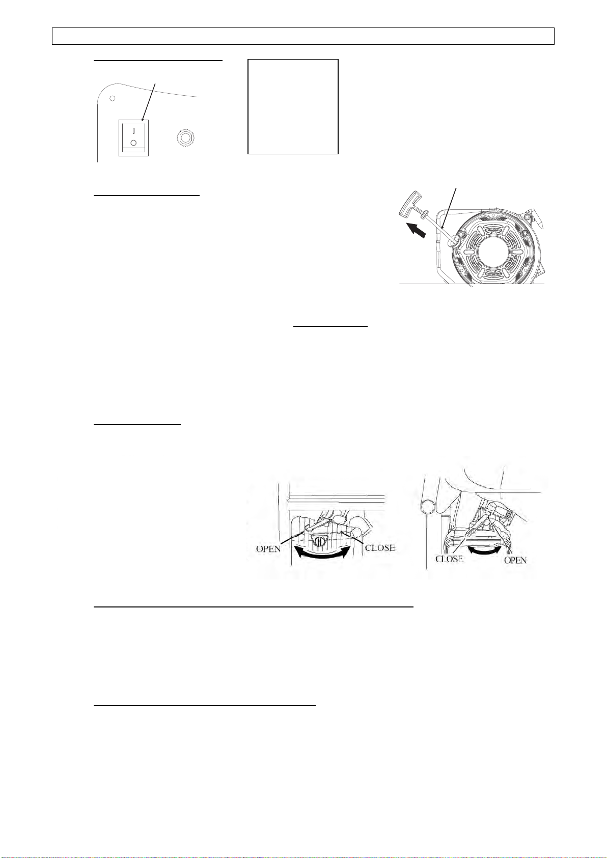
1. GENERATOR SWITCH
2. RECOIL STARTER
To start the engine, pull the starter grip lightly until resistance
is felt, then pull briskly.
Do not allow the starter to snap back against the engine.
Return it gently to prevent damage to the starter.
3. FUEL VALVE
The fuel valve controls fuel flowing from the fuel tank
to carburetor. Be sure to return the lever to “OFF”
after stopping the engine.
4. CHOKE LEVER
The choke lever is used to provide an enriched fuel mixture when starting a cold engine.
Slowly put the choke lever to “OPEN” position after the engine is heated.
5. AC CIRCUIT BREAKER / OVERCURRENT PROTECTOR
The overload current will automatically switch off circuit breaker to avoid short circuit of the
load or overload. If the indicator of AC Overcurrent Protector is raised, the Over-current
Protector is now in the “OFF” position. Press the button of AC Over-current Protector to
the “ON” position again a few minute later. If the circuit breaker is switched OFF
automatically, switch the circuit breaker ON again.
6. OIL ALERT SYSTEM
The oil alert system is specially designed to prevent engine damage caused by an
insufficient amount of oil in the crankcase. When the oil level in the crankcase falls down
below a safe limit, the oil alert system will automatically shut down the engine (though the
generator switch still remain in the ON position), so that the engine can’t be damaged
resulting from the insufficient amount of the oil.
STARTER GRIP
GENERATOR SWITCH
ON
OFF
7

GENERATOR OPERATION
Generator operation environment:·
Temperature:-15℃~40℃·
Humidity: 95% lower.·
Height above sea level: 1000 m lower (If the area is 1000 m over, the power should be
lowered in operation).
1. CONNECTION TO THE HOUSEHOLD POWER SUPPLY
When connecting the generator to the household power supply, connection must be
made by a qualified electrician. After connecting, carefully check electric
connections for their safety and reliability.
Unsafe connections will result in generator damage and risk of fire.
2. AC CURRENT
Before starting the generator, make sure that total
load appliance power (Total resistance, capacitive
and inductive) does not exceed rated power of the
generator
Overload operation will greatly shorten
generator service life.
If the generator set is connected to multi- loads or
electric appliances, please first connect to current
maximum, in turn, current second, and final,
current minimum.
8

In general, capacitive and inductive load, especially, motor-driven devices have a big
starting current when starting.
3. HIGH ALTITUDE OPERATION
At high altitude, the standard carburetor air-fuel mixture will be excessively rich. Output
power will decrease, and fuel consumption will increase. Engine performance can be
improved by installing a smaller diameter main fuel jet in the carburetor and readjusting the
pilot screw. If you always operate the engine at altitudes above sea level 1000 meters,
have our company authorized dealer perform this carburetor modification. If not, lower load
power in operating generator.
Even equipped with suitable carburetor, engine horsepower will decrease approximately
3.5% for each 300 meter increase in altitude. The effect of altitude on horsepower will be
lowered greater than this if no carburetor modification is made.
If a carburetor for high altitude is equipped with engine suitable to a lower altitude,
the lean air fuel mixture will cause the engine output power lowering, over-heat and
seriously damage.
PRE-OPERATION CHEK
1. ENGINE OIL
Engine oil is a major factor affecting engine performance and service life. Non-
detergent and 2-stroke engine oils will damage the engine and are not
recommended. Check the oil level before each use with the generator on a level
surface with the engine stopped.
Recommended oil
4-stroke gasoline oil
API service Classification's SF
or SAE10W-30 of equivalent SG class.
Method of check oil level:
Remove the oil filler cap and wipe the dipstick clean.
Check the oil level by inserting the dipstick into the filler neck without screwing it in.
If the level is low, add the recommended oil to the upper mark on the dipstick.
After adding, don’t forget to reinsert and screw down the oil dipstick.
9
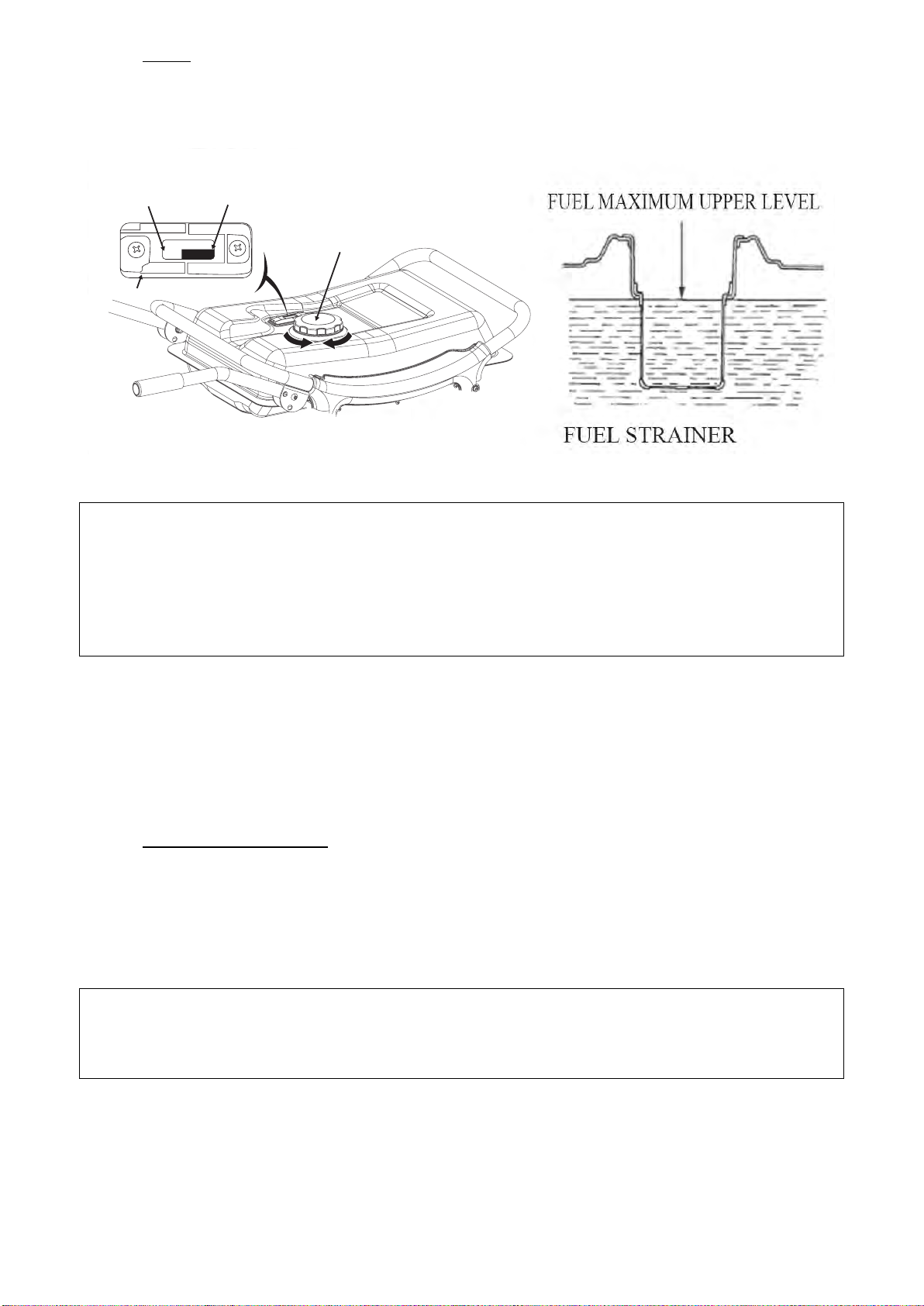
2. FUEL
1. Check the fuel level gauge,
2. Refill the tank if the fuel level is low. Do not fill above the shoulder of the fuel strainer.
3. Reinstall and screw down the fuel tank cap after refuelling.
• Refuel in a well-ventilated area with the engine stopped. Do not smoke or allow
flames or sparks in the area where the engine is refuelled or where gasoline is
stored.
• Do not overfill the fuel tank.
• Avoid repeated or prolonged contact with skin or breathing of vapour.
• Keep out of reach of children.
• Don’t use the oil and gasoline mixture or gasoline contained impurity.
Use gasoline with octane rating ≥90 .
We recommend unleaded gasoline because it produces fewer engine and spark plug
deposits and extends exhaust system life.
Never use stale or contaminated gasoline or oil/gasoline mixture. Avoid getting dirt or
water in the fuel tank.
3. BATTERY (WX6200ES, WX6250ES, WX7000)
Don’t connect the battery positive and negative poles in reverse. Reversed
connection can seriously damage the generator set and battery.
• If operated improperly, the battery may be explosive and potentially hurt others
nearby. Keep the fire and inflammable materials far away from battery.
• The battery will release the explosive gas, please keep the fire far away from
battery. Keep the air ventilating when battery is charging and using.
FUEL TANK CAP
EMPTY
FULL
FUEL LEVEL GAUGE
10

STARTING THE ENGINE
1. RECOIL STARTER
1. Remove all the loads out of the output.
2. Turn the fuel valve to the “ON” position.
3. Turn the AC circuit breaker to the “OFF” position.
4. Turn the choke lever to the “CLOSE” position.
Don’t close the choke when starting the engine in warm state
5. Turn the generator switch to the “ON” position.
6. Pull the starter grip until compression is felt, then pull briskly.
7. Turn the choke lever to the “OPEN” position after the engine is warm.
8. Don’t use electric apparatus before setting circuit breaker to the “ON” position.
2. ELECTRIC STARTING (WX6200ES, WX6250ES, WX7000)
1. Remove all the loads out of the output.
2. Turn the fuel valve to the “ON” position.
3. Turn the choke lever to the “CLOSE” position.
Don’t close the choke when starting the engine in warm state.
4. Turning the generator switch to electric starting position.
5. After starting engine, immediately release generator switch and generator switch can
automatically return to open position.
6. Turn the choke lever to “OPEN” position after the engine is warm.
Turn the generator switch to electric starting position for more than 5 seconds can
damage the starting motor. If failing to start, release the switch and wait 10 seconds
before operating it again.
If the speed of the starting motor drops fast after a period of time, it means that the
battery should be recharged.
STOPPING THE ENGINE
1. Turn the AC circuit breaker to the OFF position.
2. Turn the generator switch to the OFF position.
3. Turn the fuel valve to the OFF position.
To stop the engine in an emergency, turn the generator switch to the OFF position.
11

MAINTENANCE
Good maintenance is essential for safe, economical, and trouble-free operation. It will also
help reduce air pollution.
Exhaust gas contains poisonous carbon monoxide. Shut off the engine before
performing any maintenance. If the engine must be run, make sure the area is well
ventilated.
Periodic maintenance and adjustment is necessary to keep the generator in good
operating condition. Perform the service and inspection at the intervals shown in the
Maintenance schedule below:
1. Service more frequently when used in dusty areas.
2. These items should be serviced by an authorized generator dealer.
3. When used more often, only servicing according to above correct intervals can
insure the generator set long-term use.
Improper maintenance, or failure to correct a problem before operation, can cause a
malfunction in which you can be seriously hurt or killed.
Always follow the inspection and maintenance recommendations and schedules in
this owner’s manual.
REGULAR SERVICE PERIOD Each
Use
First
Month
or 20
Hrs.(3)
Every
3
Months
or 50
Hrs. (3)
Every
6
Months
or 100
Hrs. (3)
Every
Year
or 300
Hrs.
(3)
Engine oil Check Level ○
Change ○ ○
Air cleaner Check ○
Clean ○ (1)
Sediment Cup Clean ○
Spark plug Clean ○ renew
Valve clearance Check-Adjust ○ (2)
Cylinder Cover Clean Every 300 Hours (2)
Fuel tank and strainer Clean Every 2 Years (2)
Fuel line Replace Every 2 Years (2)
WX2200–WX3200
Cylinder head and the
head of piston
Clean carbon Every 125 hours (2)
WX6200–WX7000
Cylinder head and the
head of piston
Clean carbon Every 250 hours (2)
12

1. ENGINE OIL CHANGE
Drain the oil while the engine is warm to assure complete and rapid draining.
1. Remove the oil dipstick and drain plug to drain the oil.
2.Reinstall the drain plug, then tighten the plug securely.
3. Refill oil and check the oil level.
Oil capacity: WX2200-WX3200: 0.6L;
WX5000-WX6200-WX6250-WX7000: 1L
Refer to the oil security card.
Dispose of the oil according to the local requirements
2. AIR CLEANER SERVICE
A dirty air cleaner will restrict air flow to the carburetor. To prevent carburetor malfunction,
service the air cleaner regularly. Service more frequently when operating the generator in
extremely dusty areas.
Using gasoline or flammable solvent to clean the filter element can cause a fire or
explosion. Use only soapy water or non flammable solvent.
Never run the generator without the air cleaner. If not, rapid engine wear will result.
1. Open the air cleaner clip and open the air cover. Check the air cleaner element for
any damage and clean.
2. If the air cleaner element is dirty, please clean the air cleaner element: Wash the
air cleaner element in a solution of household detergent and warm water, then rinse
thoroughly or wash in non flammable or high flash point solvent: Pour a few drops
of engine oil, on the oil filter element then squeeze out.
13
3. Reinstall the air cleaner element and the cover.
3. FUEL SEDIMENT CUP CLEANING
1. Turn the fuel valve to the OFF position. Remove the
sediment cup, o-ring and strainer according to the
arrow direction.
2. Clean the sediment cup, and o-ring, and strainer in
non flammable or high flash point solvent.
3. Reinstall o-ring, and strainer and screw down the
sediment cup.
4. Turn the fuel valve ON and check for leaks.
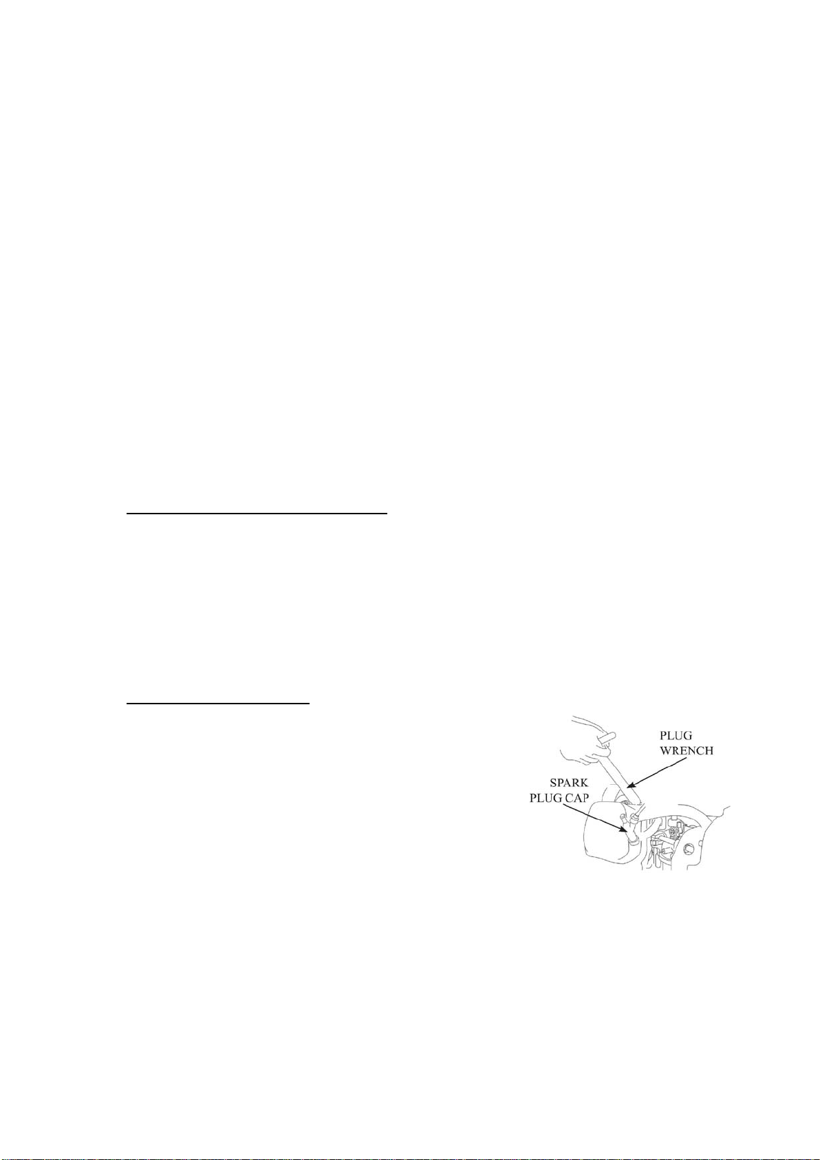
4. SPARK PLUG SERVICE
1. Recommended spark plugs: F7RTC or other
equivalents
2. Remove the spark plug cap.
3. Use the plug wrench to remove the spark plug.
4. Visually inspect the spark plug if the insulator is
cracked. If cracked, replace with new the spark plug.
5. Measure the plug gap with a feeler gauge. Correct as
necessary by carefully bending the side electrode. The
gap should be: 0.70-0.80 mm.
6. Check the spark plug washer for damage.
7. Reinstall the spark plug, tighten it with plug wrench and impact the washer. Reinstall
the spark plug accurately.
Please use the spark plug with suitable heat range.
14

STORAGE
Do not touch a hot engine or exhaust system to avoid burns or fires. Let the engine
cool before storing the generator.
If storing the unit for an extended period, be sure the storage area is free of excessive
humidity and dust.
1. Drain the fuel in the fuel tank out, clean strainer, o-ring and sediment cup, then
reinstall. Drain fuel out of the carburettor by loosening the drain screw, then
reinstall and screw down the carburetor screw.
Gasoline is extremely flammable and is explosive under certain conditions. Drain
fuel in a well ventilated area with the engine stopped. Do not smoke or allow flames
or sparks in the area during this procedure.
2. Screw the oil dipstick off and screw the drain bolt off the crankcase to completely
drain the oil out. Then screw down the drain bolt and fill fresh oil to upper mark,
finally reinstall the oil dipstick.
3. Remove the spark plug, and pour about a tablespoon of clean engine oil into the
cylinder. Crank the engine several revolutions to distribute the oil, then reinstall the
spark plug.
4. Slowly pull the starter grip until resistance is felt. Leave the intake and exhaust
valves in the closed position.
5. Place the generator in the clean area.
15
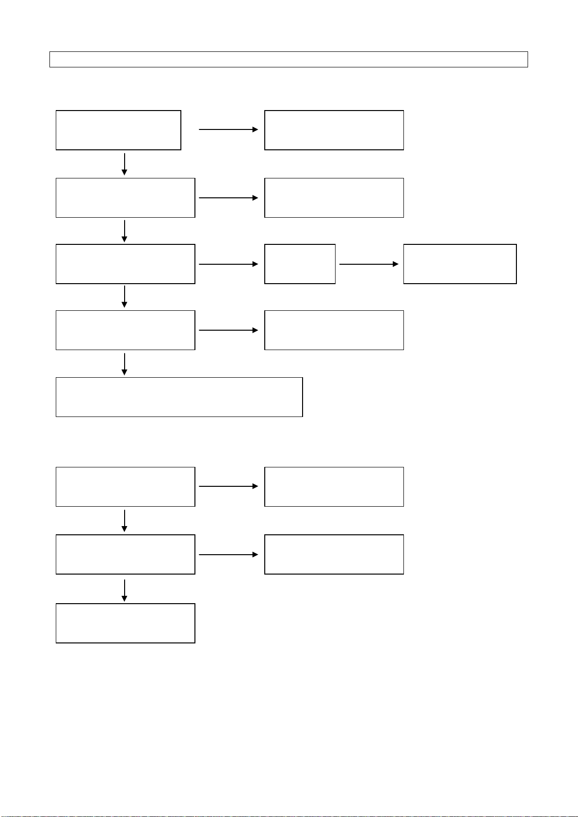
TROUBLESHOOTING
ENGINE UNABLE TO START:
NO POWER SUPPLY:
Is there fuel in the tank?
Refill the fuel tank.
Is there enough oil in the
engine?
Add the recommended oil.
Is there a spark from the
spark plug?
Replace the
spark plug
Take the generator to
an authorized dealer.
Is the fuel reaching the
carburetor?
Check and clean the fuel
sediment cup.
If the engine still does not start, take the
generator to an authorized generator dealer.
NO
NO
NO
NO
Still NO
spark
YES
YES
YES
YES
Is the AC circuit breaker
ON?
Turn the AC circuit
breaker ON.
Check the electrical
appliance or equipment for
any defects.
Take the generator to an
authorized dealer.
NO
NO
YES
Replace the electrical
appliance or equipment.
YES
16

WHEEL KIT
1. Install the two wheels on the wheel axle with gaskets and pins.
2. Install the wheel on the bottom plate of the generator frame with bolts and nuts.
3. Fix the handle on the frame.
17

CE DECLARATION
SERIAL NUMBER PLATES
Manuale Uso e Manutenzione
WX2200
WX3200
WX5000
WX6200 / WX6200 ES
WX6250 / WX6250 ES
WX7000

Grazie per aver scelto un gruppo elettrogeno della nostra Azienda.
Questo manuale contiene le informazioni per l’uso e la manutenzione del generatore.
Leggere attentamente le istruzioni prima di usare il generatore.
Un uso corretto e sicuro, vi aiuterà ad ottenere i migliori risultati.
La Casa Costruttrice si riserva il diritto di effettuare modifiche ai propri prodotti in qualsiasi
momento, senza preavviso e senza incorrere in alcuna sanzione. Questo manuale nè
parte di esso potrà essere riprodotta senza autorizzazione scritta da parte della Casa
Costruttrice.
Tutte le informazioni qui riportate sono basate sui dati disponibili al momento della stampa;
il contenuto di questo manuale potrebbe essere diverso dalle parti reali dovuto a revisioni
o altre migliorie.
Il presente manuale deve essere considerato parte integrante del generatore e dovrà
essere incluso all’atto di vendita.
INDICAZIONI DI SICUREZZA
La Vostra sicurezza e la sicurezza degli altri è molto importante.
Nel manuale del generatore troverete importanti indicazioni per la sicurezza. Leggere
questi messaggi attentamente.
I messaggi sulla sicurezza Vi allerteranno sui potenziali rischi in cui potrete incorrere Voi o
altre persone. Ogni messaggio di sicurezza è preceduto dal simbolo di pericolo e una delle
seguenti parole: PERICOLO, ATTENZIONE o AVVERTENZA.
Il mancato rispetto delle istruzioni PROVOCHERÀ la MORTE o GRAVI
LESIONI PERSONALI
Il mancato rispetto delle istruzioni POTREBBE provocare la MORTE o
GRAVI LESIONI PERSONALI
Il mancato rispetto delle istruzioni POTREBBE provocare LESIONI
PERSONALI.
Il mancato rispetto delle istruzioni potrebbe provocare danni al generatore o
ad altre proprietà
PR INDUSTRIAL s.r.l.
Loc. Il Piano
CAP 53031, Casole D’Elsa (SI)
ITALIA
This manual suits for next models
7
Table of contents
Languages:
Other Pramac Portable Generator manuals

Pramac
Pramac P2200i User manual

Pramac
Pramac E3100 User manual

Pramac
Pramac E3750 User manual

Pramac
Pramac P Series User manual

Pramac
Pramac S5500 User manual

Pramac
Pramac E5000 User manual

Pramac
Pramac E3750 User manual

Pramac
Pramac S3100 User manual

Pramac
Pramac Powermate PMi1000 User manual

Pramac
Pramac ES5500X 5.5 KW Owner's manual

Pramac
Pramac P7500i User manual

Pramac
Pramac S2800 User manual

Pramac
Pramac GA20000 User manual

Pramac
Pramac PMi 2000 User manual

Pramac
Pramac S6000 User manual

Pramac
Pramac Pmi3000 User manual

Pramac
Pramac S3100 User manual

Pramac
Pramac LP3200 User manual

Pramac
Pramac TG 12/3 User manual

Pramac
Pramac WX6200ES User manual


