Pramac ES5500X 5.5 KW Owner's manual

Supplemental Instructions
for
Pramac ES5500X 5.5 KW
Generator Set
1 December 2003
NSWC Coastal Systems Station
Panama City, FL

1
This package includes the following supplemental items and instructions to be used
with the previously shipped Pramac ES5500X 5.5 KW Generator Set, supplied as part
of the USS Cole damage control lessons learned package:
a. Pramac Industries Technical Service Bulletin 1001 (Power Panel Rewiring
and Ground Removal)
b. Wiring Check Template (used during power panel rewiring)
c. Repair Parts Kit for Generator (submit to Supply Officer)
d. Installation instructions for adding replacement fuel prime line (air vent)
e. Generator Mobility Kit (Ancillary equipment)
f. Allowance Parts List (APL) 16A030002
g. Maintenance Index Page (MIP)/Maintenance Requirement Cards (MRCs)
The Pramac Industries service bulletin (TSB 1001) for the ES5500X generator
series, dated 23 June 03, accomplishes two tasks: (1) corrects an incorrect wiring
problem of the power panel to allow a full 40 amp service to the duplex receptacles, and
(2) removes an incorrectly-wired ground, allowing the 10” damage control circular saw
to function with this generator.
As an aid to rewiring the panel, two figures, included immediately following TSB
1001, may be used as a guide. The first figure is a template that may be inserted
directly above the terminal board before and after the rewiring steps to determine if the
wiring to the terminal board is correct. The second figure illustrates use of the template
during rewiring.
When following TSB 1001, also note these discrepancies:
•Pramac does not need to be contacted for the replacement part (as indicated
on the TSB); it is provided as part of this delivery.
•It is very easy to overlook the remark in the TSB that there are two proce-
dures included in the instruction. Be sure to read through both sets of
instructions first. Note that when step #13 of procedure 1 is complete, DO
NOT PUT THE UNIT BACK TOGETHER, but proceed to step #2 of the
second procedure. After step #5 of the second procedure, go back to step
#14 of the first procedure, and finish.
During evaluation of the TSB, it was determined that it should require no more
than 45 minutes to perform.
A repair parts kit is also provided. This kit should be submitted to the supply
officer. Parts in this kit match the APL for the generator set.
In addition to the above TSB, the Coastal System Station has developed two
modifications to improve operation and mobility of the generator, including a fuel system
air purge, which allows the fuel system to be purged of air without removing fuel lines.
The second modification is a generator mobility kit, which consists of wheels and
handles. Information on both modifications is also found in this package.
Any questions concerning the above may be addressed to Mr. K. Powell, NSWC
CSS Panama City, Code E50L, Commercial (850) 234-4198, DSN 436-4198, or E-Mail

Pramac Industries
SERVICE BULLETIN TSB1001
Page 1of 3
Date: 23-Jun-03
PRODUCTS INVOLVED
ES5500X(ES5500MYHDI-AB00W) generators with serial numbers between 2002US21034 and
2003US25890.
ISSUE
Some generators may have been produced with the wiring between the alternator and the electrical
panel connected improperly. There may also be a ground to neutral jumper wire in the control panel.
This bulletin has been produced to define parts and procedures in correcting the wiring.
SYMPTOMS
On generators with this problem, one of the circuit breakers will trip upon cranking. This can go un-
noticed because the generator may continue to perform, however, maximum capacity cannot be
obtained. The circuit breakers also have weather boots, which can disguise the fact that the circuit
breaker has tripped. There may also be problems with the GFCI tripping when using certain tools,
specifically a Milwaukee brand 6460 circular saw. Note: This does not present a safety problem.
ACTIONS
For generators within the defined serial number range and model number experiencing the
previously described problems a new wiring harness, part number PIT0005, will be provided under
warranty. Contact the Service/Warranty Manager at (770) 479-2922 and reference this TSB number.
Note that the existing wiring diagram in the generator manual is correct and may be used when
connecting the new wire harness. An electrical diagram is also shown on page 2. Where the ground
to neutral jumper exists on the panel, use the following procedures to remove it.
There are 2 sets of procedures below. If your generator exhibits both problems the corrective actions
can easily be combined. Read both sets of procedures thoroughly.
Upon receipt of the wiring harness from the Service/Warranty Department follow the steps below to
correct the generator wiring.
Tools required: Phillips head screwdriver, small standard screwdriver, 10mm Socket or wrench.
Make certain that the generator is not running before beginning. Read the instructions completely
before beginning work. Refer to page 2 for photos showing the harness correctly installed.
1. Remove the back cover from the alternator using a Phillips head screwdriver and removing
the 4 screws in the corners.
2. Disconnect the green wire from the alternator body inside the panel with the same
screwdriver.
3. Disconnect the existing harness from the alternator by pulling the white connector apart.
4. Remove the bolts around the perimeter of the control panel using the 10mm socket or wrench
and rotate the panel down.
5. Using the standard screwdriver, disconnect the existing harness(5 wires –1 green, 2 white, 2
black) from the bottom of the terminal block which is mounted on the control panel.
6. Remove the existing harness from the generator and discard. Route the new harness into
roughly the same position as the old one.

Pramac Industries
SERVICE BULLETIN TSB1001
Page 2of 3
7. Connect the white connector of the new harness to the white connector in the alternator
noting that the wire colors of the new harness correspond to those on the alternator.
8. Connect the green wire with the ring terminal on the end to the same ground position in the
alternator as the previous harness using the same screw.
9. In the control panel, connect the Green wire from the harness to the position on the
connector block opposite the green wire.
10. Connect the Brown wire of the harness to the position on the connector block opposite the
white wire which connects directly to one of the receptacles.
11. Connect the Blue wire of the harness to the position on the connector block opposite the
black wire which connects directly to one of the receptacles.
12. Connect the White wire of the harness to the position on the connector block opposite the
white wire which connects directly to one of the circuit breakers.
13. Connect the Black wire of the harness to the position on the connector block opposite the
black wire which connects directly to one of the circuit breakers.
14. Reinstall the control panel and the alternator end cap.
15. Make certain that all circuit breakers are re-set by pushing the black buttons on the front of
the control panel. Note that these buttons may be hidden by weather boots.
Elec. Diagram –Control Panel
Figure 1. Alternator Figure 2. Control Panel

Pramac Industries
SERVICE BULLETIN TSB1001
Page 3of 3
Follow the steps below to remove the ground to neutral jumper wire.
Tools required: Phillips head screwdriver, 10mm Socket or wrench.
Make certain that the generator is not running before beginning. Read the instructions completely
before beginning work.
1. Remove the bolts around the perimeter of the control panel using the 10mm socket or wrench
and rotate the panel down.
2. Locate the ground to neutral jumper. It should be a green wire connected from a
ground(green wires) point to a neutral(white wires) point. Reference Figure 3 below for the
typical position, circled in red. Note that the jumper could possibly be on any of the
receptacles but should be as shown below.
3. Loosen the green screw on the receptacle where one end of the jumper is connected and
remove the jumper from that position. Re-tighten the screw.
4. Loosen the silver screw on the receptacle at the other end of the jumper wire. Remove the
jumper from that position. Re-tighten the screw making sure that the white wire remains
connected. Discard the jumper wire.
5. Reinstall the control panel.
6. Make certain that all GFCI receptacles are reset by pushing the reset buttons on the front of
the receptacles.
Figure 3. Control Panel

5
WIRING HARNESS TEMPLATE

6
USING THE WIRING HARNESS TEMPLATE

7
PRAMAC ES5500X 5.5 KW GENERATOR SET
REPAIR PARTS KIT LIST
ITEM PART NO. QTY
O-ring 24341-000224 1
Rope 114650-76630L 1
Knob 160910-76620 1
Strainer (oil filter) 114250-35110 1
Fuel Filter W3-1/2 1
Air Filter 114650-12590 1

8
Installation Instructions for Adding Replacement Fuel Prime Line
(Air Vent) for Pramac ES5500X 5.5 KW Generator Set
1 December 2003
NSWC Coastal Systems Station
Panama City, Florida
1. Close fuel valve on bottom of fuel tank.
2. Ensure Engine Speed Lever is in the STOP position.
3. Disconnect the rubber fuel supply line from the engine and cut to 6” length (Figure
1).
Figure 1
4. Disconnect metal supply line from injector pump (Figure 2).
Figure 2
5. Remove the three nuts holding the fuel injector pump to engine; remove pump from
engine.
6. Remove hose barb fitting (that rubber supply line was connected to) from the fuel
injector pump.
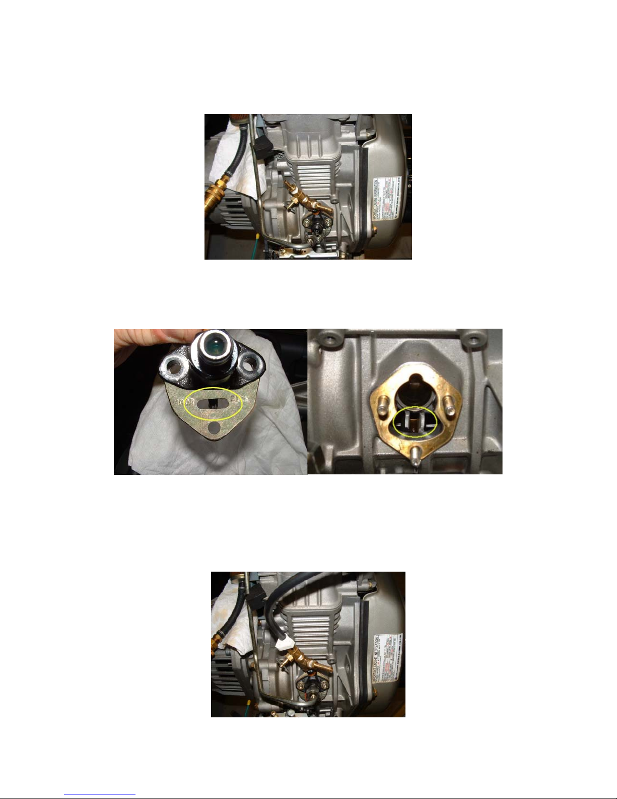
9
7. Install in its place the new brass tee with valve and hose barbs. Note the position
shown in Figure 3.
Figure 3
8. Reinstall fuel injector pump, ensuring the fuel control pin (Figure 4) lines up in the
middle of the guide on the engine (Figure 5).
Figure 4 Figure 5
9. Install the three nuts holding the fuel injector pump.
10. Reconnect the metal fuel supply line in its original position.
11. Connect the new vent line to the hose barb on the new valve (Figure 6); install
clamp.
Figure 6

10
12. Reconnect the rubber fuel supply line to the other hose barb (Figure 7); install
clamps.
Figure 7
13. Remove fuel return hose on top of the engine and cut to 9” length.
14. Install new vent hose with tee to the injector and attach vent hose to the tee (Figure
8); install clamps.
Figure 8
15. Remove top intake manifold bolt and install clamp provided with kit (Figure 9).
Figure 9

11
16. Remove fuel return hose from fuel tank. Replace hose barb on quick-disconnect
with new hose barb and hose with clamps in kit (Figure 10).
Figure 10
17. Completed installation should look like Figure 11.
Figure 11

12
MOBILITY KIT, GENERATOR
1. Kit Contents (See Figure 1).
(1) Two wheel assemblies with fasteners (4 each hex head bolts with 4 each
nylok nuts).
(2) Two handle assemblies (1 right, 1 left). Handles are marked on the inside
of the clamping area with either an “R” for right side handle or “L” for left
side handle.
(3) Two handle caps with fasteners (4 each socket head screws).
Figure 1. Kit Contents
13
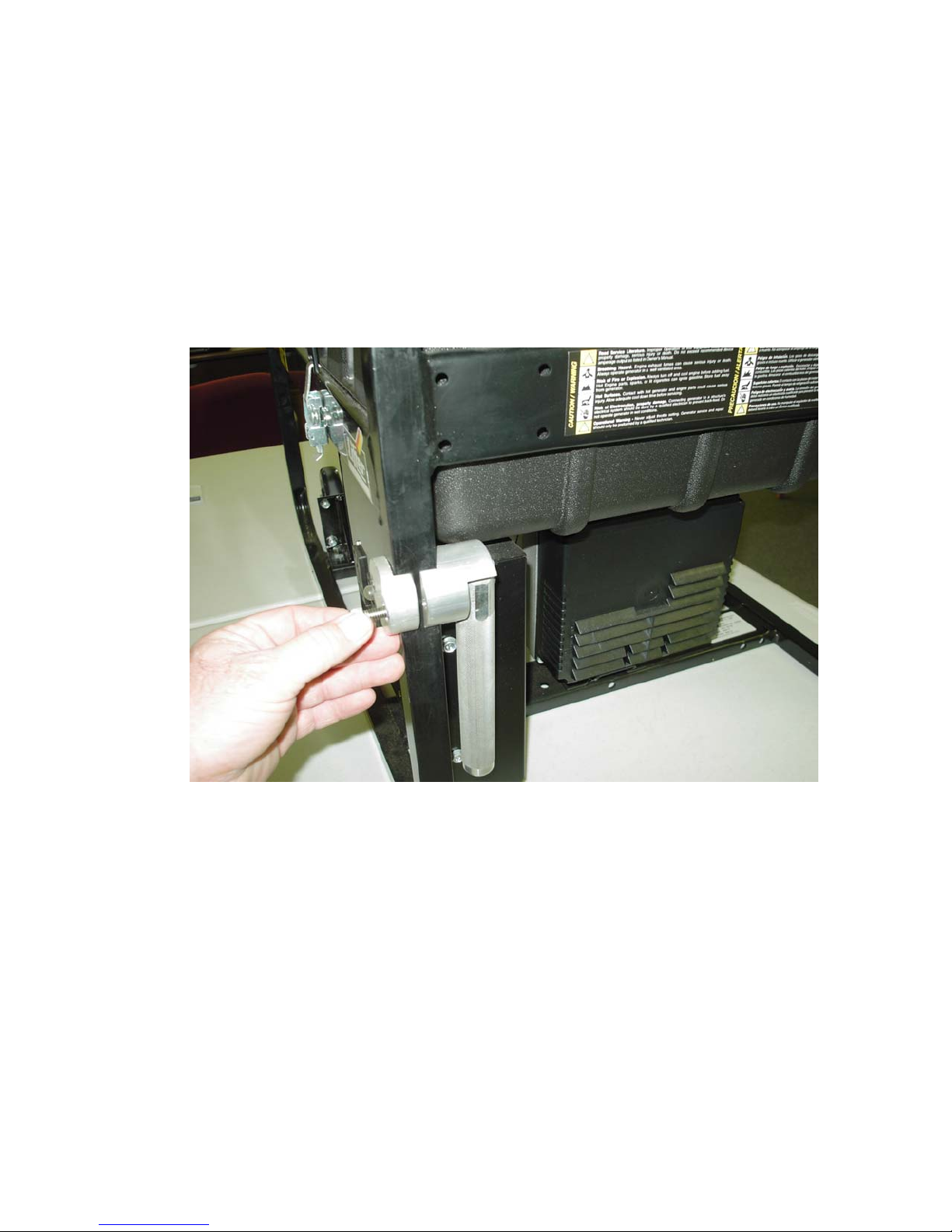
2. Handle Installation (See Figure 2).
(1) Tools required: 1 each, ¼” Allen Wrench (Hex Key)
(2) Using the “L” handle assembly, one handle cap, and two socket head
screws, install the left handle on the upright brace approximately 1” below
the horizontal brace on the left side of the generator (see Figure 2).
(3) Installation of the right side handle is identical to the left handle.
Figure 2. Handle Installation

14
3. Wheel Installation (See Figure 3).
(1) Tools Required: 1 each, ½” socket with ratchet.
1 each, ½” combination wrench
(2) Using one wheel assembly, two hex head bolts, and two nylok nuts, install
one wheel on the right side of the generator, as shown in Figure 3. (Note
bolt holes provided in generator frame for this purpose.)
(3) Installation of the left wheel assembly is identical to the right wheel.
Figure 3. Wheel Installation

ALLOWANCE PARTS LIST (APL)
EQUIPMENT/COMPONENT NOMENCLATURE/CHARACTERISTICS MANUAL IDENTIFICATION NO. DATE PAGE
TECHNICAL
DOCUMENT
NUMBER PLAN
ON BOARD ALLOWANCE TABLE
NUMBER
OF EQUIPMENT/COMPONENTS
1 2 3 4 5-8 9-20 21-50
REFERENCE SYMBOL NUMBER ITEM NAME STOCK NUMBER 1 2 3 4 5-8 9-20 21-50
ALLOWANCE PARTS LIST (APL)
SHIP TYPE & HULL NO.
P S A
A S U L
R O M R P N L
T U A E P O QTY. I
M R I C S T IN ONE T
E C N O R E EQPT./ E
C E T V C S COMP. U/I M
P S M R S N QTY. U/I A
A O A E U O IN ONE I
R U I C P T EQPT./
T R N O P E COMP.
M C T V S S
E E R
C C
E
1
2
2
8
A
GENERATOR SET, DIESEL, 5.5KW
16A030002 12-17-03 1
MFR-PRAMAC INDUSTRIES, INC CANTON GA
NAVCOM PLAN-N/A
MFR DWG-N/A
MFR ID-ES5500X
PATTERN NO-0010
EQUIP SPEC-N/A
NSN-NONE
LAPL-NSWC-DD ENGINEERING REVIEW
MODEL- PRAMAC ES5500X 5.5KW GENTERATOR SET
SURGE WATTS-5500 WATTS
CONT.WATTS-4950 WATTS
VOLTAGE-120/240 VAC (SINGLE PHASE)
ENGINE-YANMAR L100
ENGINE HP-10 HP
TSA IS NSWC-DD CODE E53, POC IS MARK BLACK
PA IS NAVICP-M CODE 058131, POC IS RON KIMMEL
FSCM-1ZKG1
CCF DATE -05 03
DP110445 1J0J6 COVER,ELECTRICAL GE 9G 6115-01-510-3098 1PAOZZ 1EAZ
ES5500X 1ZKG1 GENERATOR,PORTABLE 7HH6115-01-501-7368 1PAODD 1SEZ
G080101 1ZKG1 FILTER,FLUID 9C 2910-01-509-7325 7PAOZZ E 1EAP
114250-35110 0AK42 STRAINER-LUBE OIL 9C 2815-01-353-7523 1PAOZZ 1EA
114252-12550 0AK42 WING NUT M8 9Z 5310-01-465-9993 1PAOZZ 1EA
114252-12560 0AK42 WASHER, SEAL 9Z 5310-01-431-3121 1PAOZZ 1EA
114650-12210 0AK42 GASKET,AIR CLEANER 9Z 5330-01-415-3800 1PAOZZ 1EA
114650-12540 0AK42 ELMT W/PREFILTER,AIR CLN9C 2940-01-311-4218 1PAOZZ E 1EAP
114660-76050 0AK42 RECOIL STARTER ASSY 9C 2990-01-416-1678 1PAOZZ 1EA
160810-76630 0AK42 ROPE,STARTER 9C 2805-01-465-6864 1PCOZZ 1EA
160910-76620 0AK42 KNOB 9Z 5355-01-415-9773 1PAOZZ 1EA
26106-060162 0AK42 SCREW,CAP,HEXAGON H 9Z 5305-01-388-6229 1PAOZZ 1EA
714650-12560 0AK42 AIR CLEANER,INTAKE 3CD2940-01-417-2344 7PFOZO 1EA
E N D
CONVENTIONAL PROVISIONING 16A030002 12-17-03 1

Table of contents
Other Pramac Portable Generator manuals

Pramac
Pramac S12000THEPI User manual

Pramac
Pramac P2200i User manual

Pramac
Pramac E3750 User manual

Pramac
Pramac P7500i User manual

Pramac
Pramac Powermate PMi1000 User manual

Pramac
Pramac S3100 User manual

Pramac
Pramac S3100 User manual

Pramac
Pramac LP3200 User manual

Pramac
Pramac S4500 User manual

Pramac
Pramac E3100 User manual

Pramac
Pramac P Series User manual

Pramac
Pramac Powermate WX 2200 User manual

Pramac
Pramac WX6200ES User manual

Pramac
Pramac Pmi3000 User manual

Pramac
Pramac E5000 User manual

Pramac
Pramac TG 12/3 User manual

Pramac
Pramac S5500 User manual

Pramac
Pramac S2800 User manual

Pramac
Pramac GA20000 User manual

Pramac
Pramac S6000 User manual


