PRATT Industries TRUSS Owner's manual

- 1 -
OWNER/OPERATOR MANUAL
Advanced Design Intermodal Equipment
*TRUSS TRAILERS *
*LUMBER DUMPER TRAILERS *
Service Notes:
This operations manual describes the basic operations and maintenance procedures for PRATT trailer/chassis.
The information contained in this manual was current at the time of printing and is subject to change without notice or liability.
You must follow your company safety procedures when you service or repair equipment. Be sure you understand all the procedures and
instructions before you begin work on the unit.

- 2 -
Table of Contents
Operator Instructions ........................................................................................................ 4
Normal Trailer Use ............................................................................................................5
PRATT Warranty Coverage ................................................................................................. 6
Operation of Rollerbed Trailer ........................................................................................ 10
Hydraulic neck assembly ........................................................................................................... 10
Hydraulic neck operation .......................................................................................................... 10
Truck requirements for charging battery .................................................................................. 10
Expanding the trailer (Expandables only) .................................................................................. 10
Unloading procedures ............................................................................................................... 11
Split unloading........................................................................................................................... 11
Bad job site conditions .............................................................................................................. 12
Self-Adjusting Slack Adjuster ........................................................................................... 13
Operation................................................................................................................................... 13
Trouble Shooting ....................................................................................................................... 13
Operational Check..................................................................................................................... 13
Maintenance .............................................................................................................................. 14
Lubrication................................................................................................................................. 14
Inspection .................................................................................................................................. 14
Coupling and Uncoupling................................................................................................ 15
Coupling Tractor-Semi trailers ..................................................................................................15
Uncoupling Tractor-Semitrailers ............................................................................................... 17
Trailer Maintenance Procedures...................................................................................... 19
Kingpin and Fifth Wheel Area....................................................................................................19
Rear Impact Guards................................................................................................................... 19
Wheel and Rim Care.................................................................................................................. 19
Spoke wheel installation and maintenance ............................................................................... 19
Hub installation
&
maintenance................................................................................................ 21
Tire Maintenance....................................................................................................................... 25
Trailer axle maintenance ........................................................................................................... 28
Care and maintenance of springs.............................................................................................. 36
Air ride suspension maintenance .............................................................................................. 36

- 3 -
Air brake maintenance............................................................................................................... 39
Hydraulic system maintenance ................................................................................................. 40
Lighting maintenance ................................................................................................................ 40
Additional Maintenance requirements for Rollerbed Trailers .................................................. 41
Lubrication....................................................................................................................... 42
Note on lubrication.................................................................................................................... 42
Wheel bearings and hubs .......................................................................................................... 42
Landing gear [two speed) .......................................................................................................... 42
Brake camshafts......................................................................................................................... 42
Brake shoes................................................................................................................................ 42
Brake roller and cam heads....................................................................................................... 42
Suspension................................................................................................................................. 42
Hydraulic oil reservoir ............................................................................................................... 42
Reservoir level check ................................................................................................................. 43
Draining oil reservoir................................................................................................................. 43
Oil recommendations................................................................................................................ 43
Trailer maintenance schedule.......................................................................................... 43
Trailer maintenance services required ...................................................................................... 43
Troubleshooting............................................................................................................... 45
Spring parking brakes................................................................................................................ 45
Brakes ........................................................................................................................................ 46
Wheels, Tires and Alignment.....................................................................................................47
Landing gear; difficulty in turning handcrank ........................................................................... 48
Electrical System: Wiring, Fuses & Circuit Breakers.................................................................. 48
Complete loss of trailer lights.................................................................................................... 49
Dim or Flickering Lights............................................................................................................. 49
Cylinder will not operate ........................................................................................................... 49
Cylinder will not hold ................................................................................................................ 49
Noisy Pump................................................................................................................................ 49
Appendix A: Maintenance Record................................................................................ 50

- 4 -
Operator Instructions
Congratulations! You have just purchased the finest trailer on the road today.
This manual has been prepared to assist you in retaining the safety, dependability, and performance that has
been built into your
PRATT
trailer. It is essential that your trailer receives periodic inspections, maintenance, and
service parts replacements.
This manual includes periodic safety checks that the trailer operator should perform.
It is important that every trailer owner and/or operator have an organized Trailer Preventative Maintenance
program (TPM). The United States Department of Transportation requires by law that maintenance records be
kept on every commercial highway vehicle. It is to your advantage to be able to show that regularly scheduled
TPM inspection checks have been made on every piece of equipment operated.
To assist you in establishing your TPM program, a bill-of-material is included in the back of this manual,
which lists the major components unique to your trailer. Please refer to this list for ordering parts. etc.
Not only will a regular TPM program assure you that you will get the most from your
PRATT
trailer, but also
you may place yourself in a favorable legal position in the event of an accident involving this equipment.
You can get help in setting up and operating a trailer preventative maintenance program by sending for a
"Maintenance Manual for Trailers and Containers". Write to the Truck Trailer Manufacturers Association, 1020
Princess Street, Alexandria, Virginia 22314.
IMPORTANT
Read this manual carefully. Should you have any questions contact
Pratt Industries, Inc. immediately for the answers.
1·800·546·7728
This manual should be kept with the trailer at all times and should
be left with the trailer when it
is
sold.
Website: www.prattinc.com
Email: [email protected]

- 5 -
Normal Trailer Use
This
PRATT
trailer was designed for operation within legal highway speed limits on reasonable road surfaces
for the type of service it was built to perform in accordance with the following:
1. This trailer was built to carry cargo within the limitations of two weight ratings on the identification plate.
These ratings, GA WR and GVWR, are:
a. The GAWR (gross axle weight rating) is the structural capability of the lowest rated member of the
running gear components: suspension and spring system, hub, wheels, and drums, rims, bearings,
brakes, axles, or tires.
b. The GVWR (gross vehicle weight rating) is the structural capability of the trailer when supported by
the kingpin and axles with the load uniformly distributed throughout the cargo space. Caution!
The maximum load indicated on the identification plate may or may not be a legal load on the
highway you plan to use.
2. This trailer will carry a total payload of the Gross Vehicle Weight Rating (GVWR) less the weight of the
trailer. The load must be uniformly distributed.
3. The cargo should be properly loaded, blocked, and braced to prevent load shifts and to comply with the
following sections of the Department of Transportation Regulations, Subpart 1 - Protection Against Shifting
of Falling Cargo:
•Section 393-100 - General rules for protection against shifting or falling cargo.
•Section 393-102 - Securement systems. To properly secure cargo, it is important that the working load
limits of tie down assemblies be known, as well as the working load limit of the anchor point. See
Table _ for working load limits on trailer anchor points.
•Section 393-104 - Blocking and bracing.
•Section 393-106 - Front-end structure. Your trailer may or may not be equipped with a 'rated'
bulkhead. It is your responsibility to ensure compliance with 393.106.
Beginning March I, 1998 all trailers were required to have anti-lock brake systems on at least one axes per
FMVSS-121 (49CFR 571.121). The type system used on your trailer is described on the Bill-of-Material
accompanying this manual (a "4S-2M" system means there are 4 sensors and 2 modulator valves controlling the
axles), (a "2S-IM" system is 2 sensors and 1 modulator valve). Refer to the manufacturer of the ABS system for
specific information on the various components.
CAUTION!
Operation of the trailer outside the limitations of this manual is against federal law and
PRATT Industries, Inc
,
design criteria. Any operation exceeding the limitations stated will void any responsibility of PRATT
Industries,
Inc
,
for the results.

- 6 -
PRATT Warranty Coverage
Effective 01/01/2003
ALL WARRANTY CLAIMS ARE SUBJECT TO PRATT INSPECTION FOR FINAL APPROVAL EVEN THOUGH
AUTHORIZATION NUMBER HAS BEEN ISSUED FOR SOME ITEMS.
U.S. and CANADA
Five (5) YEAR - 100% Fabricated Frame parts and Labor
All container chassis, drop frames, drop decks, goosenecks, hydraulic chassis, platform and Single Drop,
double drop, Eight (8) Axle, B-Trains, Log, Folding Pole, Telescopic, Low Boy and all special units rated for
GVWR 63,000 to 100,000 pounds, the main beams, fabricated components, steel construction, workmanship
are covered 100% for five (5) years. Unit must be used as designed; any modifications or loads that exceed the
rated G.V.W.R. void all warranties.
ONE (1) YEAR -100% PARTS and LABOR
All parts that are removable/replaceable and are limited to hydraulic system, airline system, electrical system,
lights, suspensions, axles, brakes, wheels, hub and drums, referred to as VENDOR SUPPLIED COMPONENTS,
are covered and warranted for one (1) year, 100% parts and labor. After this time period, the original
equipment manufacturer of the above said components applies.
All hydraulic cylinders, telescopic cylinders, pneumatic cylinders are covered for thirty days (30 days) for
100% parts and labor. After this warranty period the terms of the warranty, that of the original equipment
manufacturer has dictated by the vendor/supplier applies 100%.
During the warranty period, the customer, which is you, incurs all shipping and handling expenses, to and
from any of the PRATT manufacturing locations, offices or to PRATT vendors/suppliers.
OPTIONAL COMPONENTS COVERAGE
Tool Boxes, Side Kit Racks, Winch and Winch Track, All removable Bulkheads, Tire Carriers and other
option items, providing the item was used as intended and no abuse or external damage has occurred.
Aluminum floors are covered against splits and weld failure providing no abuse and correct loading practices
have been performed. Wood floors are covered for ONE (I) Year providing the failure occurs at the finger joint.
Break through, Wind Shake, Shrinkage; Splits at fasteners are not warranty items.
Transdeck Floors are covered for FIVE (5) Years against break through provided the correct loading practices
are used as well as correct lift truck tire size. Cracks and chips in the top or bottom laminate are not covered by
warranty. TRANSDECK MUST APPROVE PRIOR TO ANY REPAIRS.
Warranty of VENDOR SUPPLIED COMPONENTS as of 01/01/2003
ELECTRICAL SYSTEMS:
Phillips Harness – One
(1)
year parts and labor, Two (2) year parts only.
Truck Light – One (1) year parts only.
Grote – One (1) year parts only.
All 4 - way, 6 - way and 7 - way plugs, One (1) year parts and (1) hour labor.
Lights - Truck Light, Grote marker lights and tag lights are not covered against failure. Truck Light super
Forty, (26) months parts only. All parts must be returned.
Truck Light Super Forty, (26) months parts only. All parts must be returned

- 7 -
Truck Light L.E.D., Five (5) Years Parts only. All parts must be returned.
NOTE: The light and harness suppliers during manufacturing protect the electrical system against
corrosion and at time of assembly. Corrosion is not considered a warranty item.
SUSPENSION AND COMPONENTS:
Hendrickson Intraax all models: Air springs 0-12 months parts and labor, 13 - 24 months parts only.
Shocks, 0-12 months parts and labor, 13-24 months parts only.
Bushings, 0-12 months parts and labor, 13-60 months parts only.
Hendrickson HT-230 and 250 all models: Air springs 0-12 months parts and labor, 13-24 months parts only.
Shocks, 24 months parts and labor
Bushings, 12 months parts and labor, 13-60 months parts only.
Button up Model Axles: Complete 12 month’s parts and labor. Preset models, 0-60 month's parts and labor,
except brake shoes which are 12 months excluding normal wear.
Air kits and Height Control valves: 12 months parts and labor. All other components, Hangers and Beam, 0-
12 months Parts and labor, 13-60 months parts only.
Neway Suspensions, All RL Models: Major components (Hangers, Beams, Bushings) 0-12 months parts and
labor, 13-60 months parts only.
Air controls (valves and regulators) 12 months’ parts and labor.
Air spring: 0-12 months parts and labor, 13-24 months parts only.
Shocks: 12 months parts and labor.
NOTE: LABOR ALLOWANCE WILL BE BASED ON NEWWAY'S SCHEDULE, WHICH WILL BE GIVEN AT
THE TIME OF AUTHORIZATION REQUEST.
Ridewell Suspension: Ridewell must approve ALL claims prior to any work or replacement of items.
Hutch Suspensions: All models 0-12 month’s parts and labor, 13-24 months parts only, providing proper
maintenance has been performed.
Reyco Suspensions: Reyco must approve ALL claims prior to any work or replacement of parts.
AXLES AND COMPONENTS:
Rockwell and Dana: 0-12 months parts and labor, 13-60 months parts only. NOTE: The following items are
cause for the warranty to be voided. If the axle is bent vertically. Incorrect lubrication or low oil leveI. bearing
adjustment not properly maintained.
Brake Drum: 0-12 months excluding wear. Cracking providing heavy heat check marks are not present.
Brake shoes: 0-12 months against separation due to loose rivets, rim cracking and bending, excluding
normal wear. The use of G-G brake lining is not recommended will cause excessive brake drum wear, which is
not covered by warranty.
Slack adjusters Automatic: All 0-12 month parts and labor, 13-60 month parts only, providing proper
adjustment procedure has been maintained.
Air chamber: Anchor Lock and M.G.M. 0-12 month parts and labor, 13-24 month parts only.
Oil seals: All brands 12 months parts and labor, or until first brake replacement.
Bearings: All brands 0-36 month’s parts and labor-providing no over heat marks are present and proper
torque has been maintained. ALL parts must be returned.

- 8 -
Synthetic lubricant: All bearings and seals are covered for 35 months parts and labor providing proper
maintenance has been performed and no mixing of lubricant has occurred. All parts must be returned.
Landing Gear: Binkley all models 0-12 months parts and labor. All parts must be returned unless otherwise
instructed.
Air Systems: Glad hands and valves are 0-12 month’s parts and labor. All parts must be returned unless
otherwise instructed.
NOTE: The use of Airline antifreeze and other contaminated voids all warranties.
A.B.S. SYSTEM: Wabco system 0-36 months parts and labor. All parts must be returned.
NOTE: All other A.B.S., PRATT will handle systems through the manufacture. No approvals will be given
until approval is obtained from the manufacture.
NOTE: A qualified technician must service all systems, and the use of airline antifreeze or other
contaminates voids all warranties.
HYDRAULIC CYLINDERS AND VALVES: Are warranted for 30 days. All warranties from 2-12 months must
be approved by the manufacture.
All gas power equipment will be warranted directly by the manufacture, and must be approved and repaired
by an authorized service center.
Tires: All warranties must be handled directly by the customer or dealer with the tire manufacture, not
through Fontaine.
Paint: 0-12 months against bond failure that exceeds 25% of the unit, excluding chipping caused by chains
and stones or other securing devices. Fontaine must approve each claim prior to any work being performed.

- 9 -
PRATT INDUSTRIES, INC.
SAMPLE WARRANTY
T
his is to certify that
PRATT INDUSTRIES, INC
warrants to the first purchaser only, the described new trailer manufactured by it to be free from defects
in materials and workmanship, when properly maintained, and under normal use and service, which means the loading, unloading and transportation of
uniformly distributed legal loads of no corrosive cargo, adequately restrained and secured in a manner which does not subject the trailer to strains or impacts
greater than are imposed by normal use. Total weight of trailer and cargo must not exceed the gross vehicle weight rating (GVWR) set forth on the vehicle
identification plate affixed to the trailer at the factory, and the loading of each axle must not exceed the gross axle weight rating (GAWR) listed on the same
plate.
PRATT INDUSTRIES, INC
sole obligation under this warranty shall be limited to the repair or replacement, at its option, of any defective part of said
trailer, which is the result of defective material and/or defective workmanship of parts furnished and installed by
PRATT INDUSTRIES, INC
. This warranty
will expire (specified time periods) from date of delivery, and repairs under this warranty shall be at repair facilities designated by
PRATT INDUSTRIES, INC.
Transportation expenses to the repair facility are to be borne by the Purchaser.
The warranty herein in expressly in lieu of any and all other warranties, expressed or implied. No implied warranty of
merchantability is made and there are no warranties, which extend to use of the trailer for purposes beyond the description hereof
The warranty herein does not apply to, and
PRATT INDUSTRIES, INC.
makes no warranties, expressed or implied with respect to:
1.
Tires .
2.
Parts, accessories, or other goods manufactured by others.
PRATT INDUSTRIES, INC
will assign to customer any warranties extended to
PRATT INDUSTRIES, INC.
by the maker or supplier of such goods.
3.
Used goods delivered hereunder, regardless of manufacturer, all of which are deliverable "As Is" and “Where Is”.
4.
Any goods which after delivery hereunder have been repaired or altered by anyone other than has been authorized and approved by
PRATT
INDUSTRIES, INC.
unless in manufacturer's reasonable opinion, such repairs are in no way responsible for the condition complained of.
5.
Goods which are not defective but may wear out and have to be replaced during warranty period including for example, but without limitation
thereto, light bulbs, electrical receptacle, paint and coatings, brakes, linings, drums and return springs, equalizer, torque rod, camshaft bushings, and
camshafts, slack adjusters, brake cylinder diaphragms, springs, slider pads, wheel bearings, oil and oil seals, rim clamps and studs, gaskets and sealers,
all types of floors, parts, and components, and the like.
LIMITATIONS ON MANUFACTURERS LIABILITY
Manufacturer and Customer agree that Manufacturer shall have no liability for any cargo loss, loss of use or any other incidental or consequential damages arising out of
this order, which are alleged to have been caused by any of the goods delivered hereunder. Customer and Manufacturer further agree that customer's sole remedy for
any defects in new goods delivered hereunder, whether customer's claim arises under the warranty set forth above, or otherwise, shall be limited to the repair or
replacement at manufacturers option within one (1) year after delivery of such goods to the first purchaser, of any defective goods, of which notice of the defects is given
by Customer to Manufacturer immediately after such defect is or ought to have been discovered and which goods are returned to Manufacturer within ten (10) days
after Manufacturer requests their return for inspection and
/or
repair or replacement.
THE PROVISIONS OF THIS WARRANTY SHALL BE INTERPRETED AND GOVERNED PURSUANT TO THE LAWS OF THE STATE OF FLORIDA and MICHIGAN.
See the Warranty Statement on your trailer for Additional conditions and terms.
TRAILER SERIAL NUMBER ___________________________________________
TRAILER MODEL NUMBER __________________________________________
DATE OF DELIVERY ________________________________________________
PRATT INDUSTRIES, INC.

- 10 -
Operation of Rollerbed Trailer
These 68,000#GVWR, Panel and Truss Rollerbed Trailers have a flat profile, with a Hydraulic Neck
Assembly, a sliding tandem, 6” air unlocking deck rollers, and 11R/22.5 tires. The deck rollers are spaced
approximately 2 ft. apart. 3’ on the front deck portions.
Hydraulic neck assembly
The hydraulic neck is an articulating arm with a hinged upper coupler plate. It’s designed to be used in
conjunction with the sliding tandem, ground level feature in its application. It is equipped with a self-
contained, 12 volt, DC hydraulic pump to supply lifting power in specific situations. The objective is to create a
more favorable angle of delivery by setting the trailer down to the ground, or near the ground, at the rear. This
system is designed for use by articulating the arm while the tandem axles are locked in a forward position. This
system will lift 12,500# from the initial position with the trailer tandems at the rear most position. The system
will lift more weight as the tandems are shifted forward which transfers more weight behind the tandems and
off the front of the trailer. The more you want to lift the farther forward you slide the tandems.
Hydraulic neck operation
The self contained, 12 volt, DC hydraulic pump in this system has a push-pull cable control switch to power
the system up and down and allow gravity movement. The system has 5 positions, 2 towards the frame, 2 away
from the frame and neutral. Two of the positions are power and two are gravity. The cable will activate the
motor and pump when it is slid into one of the power positions.
#1-All the way towards the operator will lift the front end up.
#2-Mid way operator will gravity the fifth wheel to the ground when the tractor is removed from the trailer
(never use #2 position, it will only allow air into the system).
#3- The middle is neutral with a ball seat that is released by pushing the red button inside the handle.
#4- Midway towards the frame and gravity will bring the front end down.
#5- All the way toward the frame will power the front end down.
NOTE: Recommend practice is to use #1 position to lift the trailer and #5 position to let the front end back
down. Hold the handle in the power position being used and immediately return to the handle to neutral the
moment the desired travel I the front is achieved. Do not allow the handle to slide into the gravity positions. Do
not allow the gravity positions to move the front end.
Truck requirements for charging battery
The trailer comes with a 12-volt battery as a power source for the hydraulic pump. A single post female
electrical receptacle has been supplied by the manufacturer for charging this battery. This receptacle is located
on the front bolster near the 7-way receptacle and is wired to the battery for charging, while the trailer is
coupled to the truck. It is necessary to have the other end of this plug wired to the truck to charge this battery.
This system requires power through a 30 AMP fuse in the fuse panel of the truck and minimum of a 6-gauge
wire leading to the plug.
Expanding the trailer (Expandables only)
1. Remove the auxiliary air line from the storage fitting-located on the driver side at the front of the rear
main frame-and connect it to the open fitting on the forward air chamber. This should immediately
disengage the frame index pins.
2. Pull the truck forward until the holes in the inner frame and the index pins on the outer frame line up
at the desired frame length.

- 11 -
3. Remove the auxiliary air line from the air chamber and replace it on the storage fitting. When the
auxiliary air line is removed, the frame index pins should engage. Sometimes it is necessary to roll the
truck back and forth, slightly, to align the pins.
NOTE: Always make sure the index pins are locked before loading the trailer and/or moving the trailer to
another location.
4. Follow the expanding procedures above when returning the trailer to the closed length.
Unloading procedures
1. Get trailer in position to unload.
2. Unlock slider bogey lock located on the driver side front of the axles for positioning the bogey to the
desired location on the main frame of the trailer by depressing the air assist device. The slide bogey lock
mechanism is a double action lever. When the air assist is activated it will apply pressure to the
mechanical lever that retracts the lock pins. The lock pins may not retract until they are unbound by the
operator using the tractor to roll the trailer back and forth, relieving the pressure against the locking pins
thereby allowing them to retract.
NOTE: Allow the air assist and the tractor to do the work. If you manually pull the lever out too far you
could rack the lever mechanism.
3. Raise rear bumper by opening the vented ball valve next to the roller unlock valve. This will raise the
rear safety bumper.
4. Unstrap and store the rear strap at the back of the trailer (this is done because this strap is difficult to
unstrap when the trailer is in the ground-level position).
5. Get in truck and get shifter in reverse.
6. Start backing up with a fair amount of speed. (This is very important because you cannot start the
process from a dead stop, you must be rolling in reverse to start the procedure.) Pull the tractor hand
valve down, this will lock the trailer axles in place, and you will be sliding the main frame of the trailer
over and through the slider bogey.
NOTE: When sliding the trailer into the ground level position, be sure to make this step a smooth, quick
motion.
7. Apply the parking brake to the truck and trailer.
8. Lock the slider bogey to the main frame at the desired position. (The desired position can be anywhere
along the slider range of motion).
9. Lift the front of the trailer by sliding the hydraulic cable into position #1 and raise the front end to the
desired height.
NOTE: The operator should try to achieve an unloading angle that does not bend the truss package until it
has touched the ground and is partially off the trailer.
10. At this point unstrap the load, store straps, and open the roller locking valve located roadside to the rear
of the landing gear, the rollers will not unlock yet, because there is no air to the trailer. (Parking brake
must be activated).
Split unloading
The back half of the rollers can be unlocked without unlocking the front half of the rollers for split loads. The
unlocking device includes a pin that connects the front and rear lock pin bars. This pin is located on the road

- 12 -
side near the middle of the trailer. To operate; remove the pin on the lock bars. This will divide the lock bars.
You may then use the roller lock valve to unlock the rear half of the rollers only.
NOTE: The hydraulic neck can be used when split unloading to lift the front end of the trailer, thus
transferring weight to the tractor to maintain traction.
1. Get back in the truck and shift into the forward position. Apply air to the truck and trailer by releasing
the parking brakes. This will also unlock the roller locking system in about 5 to 7 seconds.
2. With the tractor in a forward gear and the parking brake released, look in the mirror on the truck you
can watch the product stat to roll off. As product starts to roll, immediately drive forward until you have
cleared the package completely. Driving forward as the product rolls off accomplishes two things in this
step. The first is that eliminate the product’s momentum as it is rolling off. This is the key to damage-
free delivery. If the truck and trailer are pulling forward when the rollers unlock, the products has very
little momentum, while rolling back because you have pulled put from under it. (When split unloading
and the load is rolling off the trailer, the load should be far enough to the rear that damage shouldn’t be
a concern.) Second, by doing this successfully you greatly reduce the possibility of high centering the
power unit when pulling forward.
NOTE: The Hydraulic Neck system should be in the raised position the entire time procedure is taking place.
This ensures that the load is distributed between the trailer tires and the tractor coupler, which prevents the
rear end of the trailer lifting the tractor by pivoting on the trailer tires. If you lose traction, use the hydraulic
pump to lift the front of the trailer and transfer weight to the truck as explained previously.
3. Now that the product is on the ground and the trailer is out from under the load, you may put the
trailer back into road position.
4. Lower the front of the trailer by sliding the hydraulic cable into position #4, gravity down. When the
trailer is completely down, slide the hydraulic cable into position #5 to tighten the coupler plate right
against the main frame of the trailer.
NOTE: DO NOT overpower the hydraulic system when tightening the coupler. Damage may occur to the
hydraulic arm and cylinder mounts by over powering the system.
5. Follow the procedures for positioning the slide bogey. Unlock the bogey with the air valve. Re-enter the
truck cab, pull the hand valve and lock the trailer brakes while driving forward. Position the bogey in
the rear position. Lock the slide box in that position using the air valve.
NOTE: Check to make sure the slide bogey is locked in place. You may have to rock the trailer back and
forth to engage all four pins.
6. Lower rear bumper back to road position by closing the ball valve.
NOTE: DO NOT hit the slide bogey too hard when sliding back to the road position. This may cause
considerable damage and IS NOT covered under warranty if evidence of abuse is apparent.
7. If the trailer is an expandable, close the trailer to a legal length for traveling by following the Expanding
Procedures.
NOTE: Check to make sure both frame index pins are locked in place.
8. Lock the rollers by closing the roller lock valves. Spin each roller to replace the roller locking pins.
9. If this was a split load, replace the pin in the lock bars.
Bad job site conditions
In muddy or rough terrain, power the hydraulic pump and lift front of the trailer to transfer weight on to the
tractor (refer to the section on the Hydraulic Neck.) It is necessary to lock the slider bogey in the forward

- 13 -
position in these conditions, because the slide bogey may start to slide back under the trailer when you pull
forward picking up on the tractor. By locking the slide bogey in the forward position, you eliminate this from
happening in bad conditions.
Self-Adjusting Slack Adjuster
Operation
Upon brake application the slack adjuster rotates and moves the
shoes into contact with the drum. The clearance notch (A)
corresponds to the normal lining-to-drum clearance. As the brake
application continues the rack (B) moves upwards and rotates the
one-way clutch (C) which slips in this direction. As the brake torque
increases the coil spring (D) load is overcome and the wormshaft is
displaced axially releasing the cone clutch. When the brake begins
its return stroke the coil spring load returns to normal and the cone
clutch is again engaged. The rack is pulled back to its original
position in the notch, and any additional travel brought about by
lining wear causes the rack to turn the locked one-way clutch and
rotates the wormshaft through the locked cone clutch. The worm
shaft then rotates the wormwheel and camshaft, adjusting the
brakes.
Trouble Shooting
TIGHT OR DRAGGING BRAKES
Check Foundation Brake Components For:
•Control arm anchor bracket not positioned properly.
•Brake chamber not fully releasing
-Spring brake not fully releasing.
-Pushrod binding on chamber housing
-Air supply not exhausting completely
•Extreme differences in lining-to-drum clearances between shoes on same wheel.
•Broken shoe return spring.
EXCESSIVE CHAMBER PUSH ROD TRAVEL
Check Foundation Brake Components For:
•Loose, broken or bent control arm anchor bracket.
•Worn camshaft bushings
•Binding camshaft.
•Worn clutch assembly.
Operational Check
Functional operation of the slack adjuster can be performed on vehicle by:
1. Block wheels to prevent vehicle from rolling.
2. Check that the push rod is fully retracted; apply air to release spring brake.
3. Manually de-adjust brakes (turn adjustment hex counterclockwise) to create an excessive clearance
condition. (A ratching sound will occur)
4. Make a full service brake application, on release; allow sufficient time for brake to fully retract. During
the brake release, observe rotation of the adjustment hex (attaching a wrench on the hex will make this

- 14 -
rotation easier to see). This rotation indicates that an excessive clearance condition has been
determined by the slack adjuster, and it is making an adjustment to compensate. On each subsequent
brake release the amount of adjustment and pushrod travel will be reduced until the desired clearance
is achieved.
5. See "In Service Checking Procedure" for proper pushrod stroke.
Maintenance
During normal chassis lube, adjusters should be inspected for damage. Check anchor brackets to ensure that
they are tight.
During reline, check the de-adjustment torque. Place a torque wrench on the 7/16" adjusting hex. Turn the
torque wrench counterclockwise and check that the clutch does not slip at a torque less than 13 Ft. Lbs. A
ratcheting sound will occur while backing off. If clutch slips at a lesser torque, the adjuster must be replaced.
Lubrication
The Self-Adjusting Slack Adjuster should be lubricated in conjunction with the lubrication prescribed for
vehicle chassis. The lubrication interval should not, however, exceed 5,000 miles or 3 months. No special
grease is required, however the use of moly-disulphide loaded grease or oil is not recommended since it may
lower friction capabilities in the adjusting clutch parts, and decrease automatic adjustment reliability.
Inspection
1. During normal lubrication intervals, visually inspect slack adjuster and anchor bracket for damage. Check
that anchor bracket is tight and the control arm is in its "Full Release" position. (Refer to Step #3
"Installation Instructions")
2. Maintaining proper brake adjustment and brake balance cannot be accomplished by the slack adjuster
alone. The condition of foundation brake components has a direct bearing on the effectiveness of brake
adjustment; therefore, periodic inspection of these components is necessary.
a. BRAKE CHAMBERS
Check that brake chamber mounting bolts are tight and proper alignment is maintained to avoid
interference between chamber pushrod and chamber housing. Verify that the brake chamber
pushrod length is equal on opposing brake chambers of the same axle
b. CAMSHAFT BUSHINGS
Optimum brake adjustment cannot be achieved when worn bushings are used.
c. WHEEL BEARING ADJUSTMENT
Accurate wheel bearing pre-load is necessary to maintain proper alignment between the brake
drum and brake shoes.

- 15 -
Coupling and Uncoupling
Knowing how to couple and uncouple correctly is basic to safe operation of combination vehicles. General
coupling and uncoupling steps are listed below. There are differences between different rigs. So learn the
details of coupling and uncoupling the truck(s) you operate.
CAUTION!
INCORRECT COUPLING AND UNCOUPLING CAN RESULT IN SERIOUS INJURY OR DEATH.
Coupling Tractor-Semi trailers
Step 1 Inspect Fifth Wheel
•Check for damaged/missing parts.
•Check to see that mounting to tractor is secure, no cracks in frame, etc.
•Be sure that the fifth wheel plate is greased as required. Failure to keep the fifth wheel plate
lubricated could cause steering problems because of friction between the tractor and the trailer.
•Check if fifth wheel is in proper positioning for coupling.
oWheel tilted down towards rear of tractor.
oJaws open.
oSafety unlocking handle in the automatic lock position.
•If you have a sliding fifth wheel, make sure it is locked.
•Make sure the trailer kingpin is not bent or broken.
Step 2 Inspect Area and Chock Wheels
•Make sure area around vehicle is clear.
•Be sure trailer spring brakes are on.
•Check that cargo (if any) is secured against movement due to tractor being coupled to trailer.
Step 3 Position Tractor
•Put the tractor directly in front of the trailer. (Never back under the trailer directly at an angle,
because you might push the trailer sideways and break the landing gear.)
•Check position, using outside mirrors, by looking down both sides of the trailer.
Step 4 Back Slowly
•Back until fifth wheel touches the trailer.
•Don't hit the trailer.
Step 5 Secure Tractor
•Put on parking brake.
•Put transmission in neutral.
Step 6 Check Trailer Height
•The trailer should be low enough that it is raised slightly by the tractor when the tractor is backed
under it. Raise or lower the trailer as needed. (If trailer is too low, tractor may strike and damage
nose of trailer; if trailer is too high, it may not couple correctly.) Check that the kingpin and fifth
wheel are aligned.
Step 7 Connect Air Lines to Trailer
•Check glad hand seals and connect tractor supply (emergency) airline to trailer supply (emergency)
glad hand.
•Check glad hand seals and tractor control (service) airline to trailer control (service) glad hand.
•Make sure airlines are safely supported where they won't be crushed or caught while tractor is
backing under trailer.

- 16 -
Step 8 Supply Air to Trailer
•From cab, push in "air supply" knob or move tractor protection valve control from the "emergency"
to the "normal" position to supply air to the trailer brake system.
•Wait until the air pressure is normal.
•Check brake system for crossed airlines.
•Shut engine off so you can hear the brakes.
•Apply and release trailer brakes, listen for sound of trailer brakes
•Being applied and released. You should hear the breaks move when applied and air escape when
the brakes are released.
•Check air brake system pressure gauge for signs of major air loss.
•When you are sure trailer brakes are working, start engine.
•
Make sure air pressure is up to normal.
Step 9 Lock Trailer Brakes
•
Pull out the "air supply" knob, or move the tractor protection valve control from "normal" to
"emergency."
Step 10 Back Under Trailer
•Use lowest reverse gear.
•Back tractor slowly under trailer to avoid hitting the kingpin too hard.
•Stop when the kingpin is locked into the fifth wheel.
Step 11 Check Connection for Security
•Raise trailer landing gear slightly off ground.
•
Pull tractor gently forward while the trailer brakes are still locked on the tractor.
Step 12 Secure Vehicle
•Put transmission in neutral.
•Put parking brakes on.
•
Shut off engine and take key with you so someone else won't move the truck while you’re under it.
Step 13 Inspection of Coupling
•Use flashlight if necessary.
•Make sure there is no space between upper and lower fifth wheel.
•If there is space, something is wrong (kingpin may be on top of closed fifth wheel jaws; trailer
would come loose very easily.)
•Go under trailer and look into the back of the fifth wheel. Make sure the fifth wheel jaws have
closed around the shank of the kingpin.
•Check that the locking lever is in the "lock" position.
•Check that the safety latch is in position over locking lever. (On some fifth wheels the catch must
be put in place by hand.)
•
If the coupling isn't right, don't drive the coupled unit; get it fixed.
Step 14 Connect the Electrical cord and Check Air Lines
•Plug the electrical cord into the trailer and fasten the safety catch.
•Check both airlines and electrical line for damage.
•Make sure air and electrical lines will not hit any moving parts of vehicle.
•
Visually inspect to see that ABS light flashes and goes out when power cord is connected. If light
stays on or comes on in use, have unit repaired at once.
Step 15 Raise Front Trailer Supports (Landing Gear)
•Use low gear range (if so equipped) to begin raising the landing gear.
•Once free of weight, switch to high gear range.
•Raise landing gear all the way up. (Never drive with landing gear
•Only part of the way up as it may catch on railroad tracks or other things.)
•After raising the landing gear, secure the crank handle safely.
•When full weight of trailer is resting on tractor:

- 17 -
•Check for enough clearance between rear of tractor frame and Landing gear. (When tractor turns
sharply, it must not hit landing gear.)
•Check that there is enough clearance between the top of the tractor tires and the nose of the
trailer.
Uncoupling Tractor-Semitrailers
The following steps will help you uncouple safely.
Step 1 Position Rig
•Make sure surface of parking area can support weight of trailer.
•Have tractor lined up with the trailer. (Pulling out at an angle can damage landing gear.)
Step 2: Ease Pressure on Locking Jaws
•Shut off trailer air supply to lock trailer brakes. Ease pressure on fifth wheel locking jaws by backing
up gently (this will help you release the fifth wheel locking lever).
•Put parking brakes on while tractor is pushing against the kingpin.
•This will hold rig with pressure off the locking jaws.
Step 3: Lower The Landing Gear
•If trailer is empty-lower the landing gear until it makes firm contact with the ground, turn crank in
low gear a few extra turns; this will lift some weight off the tractor. (Do not lift trailer off the fifth
wheel.) This will
•- Make it easier to unlatch the fifth wheel;
•- Make it easier to couple next time.
Step 4: Disconnect Air Lines and Electrical Cable
•Disconnect airlines from trailer. Connect airline glad hands to dummy couplers at back of cab, or
couple them together.
•Hang electrical cable with plug down to prevent moisture from
•
•Entering it.
•Make sure lines are supported so they won't be damaged while driving the tractor.
Step 5: Unlock Fifth Wheel
•Raise release handle lock.
•Pull the release handle to the "open" position.
•Keep legs and feet clear of the rear tractor wheels to avoid serious injury in case the vehicle moves.
Step 6: Pull Tractor Partially Clear of Trailer
•Pull tractor forward until fifth wheel comes out from under trailer.
•Stop with tractor frame under trailer (Prevents trailer from falling to ground if landing gear should
collapse or sink.)
Step 7: Secure Tractor
•Apply parking brake.
•Place transmission in neutral.
Step 8: Inspect Trailer Supports
•Make sure ground is supporting trailer.
•Make sure landing gear is not damaged.

- 18 -
Step 9: Pull Tractor Clear of Trailer
•Release parking brakes.
•Check the area and drive the tractor clear.

- 19 -
Trailer Maintenance Procedures
THE IMPORTANCE OF FREQUENT INSPECTION AND PREVEN· TATIVE MAINTENANCE
FOR ANY MACHINE CANNOT BE OVER EMPHASIZED: YOUR
PRATT
TRAILER IS NO
EXCEPTION. PROPER CARE GREATLY REDUCES THE REPAIR COST AND THE AMOUNT
OF DOWNTIME.
Kingpin and Fifth Wheel Area
Inspect the kingpin for excessive wear, rough edges, looseness, broken or chipped out areas and cracks. Any
kingpin showing such condition must be replaced at once. Do not, under any circumstance, weld the kingpin
to compensate for wear. Once a kingpin has been heated its physical characteristics are changed and its
subsequent performance cannot be predicted.
Check and inspect the fifth wheel area for cracks, breaks, and for secure attachment to the trailer. Any
welding performed in this area is to be restricted to those welds specified by PRATT and is to be performed in
the manner prescribed by PRATT.
We suggest all repairs on the kingpin area be performed only by an authorized location referred by PRATT.
Rear Impact Guards
Your new PRATT Trailer has been designed & tested to meet the requirements of N.H.T.S.A. article 571.223
and 571.224.
The rear bumper should be checked during regular maintenance for cracks, bonds & etc. If repair is needed
please refer to T.M.C. Recommended Practice 732(T).
Wheel and Rim Care
Standard wheels on your PRATT trailer are cast spoke or steel disc wheels. Wheel nuts are inspected and
tightened to specifications at the factory and are checked again at pre-delivery. To maintain the correct torque
on the wheels of a new trailer the nut torque must be checked periodically. During normal highway operation
of a new trailer, this check should be made at the first 100,500, and 1,000 miles and every 5,000 miles
thereafter. Severe service conditions may require more tightening. Loose wheel nuts may cause shimmy,
uneven tire wear, and vibration. Elongated stud holes in the wheels may result from loose hub nuts. Wheel and
hub nuts must be torqued to proper specifications to provide maximum service life.
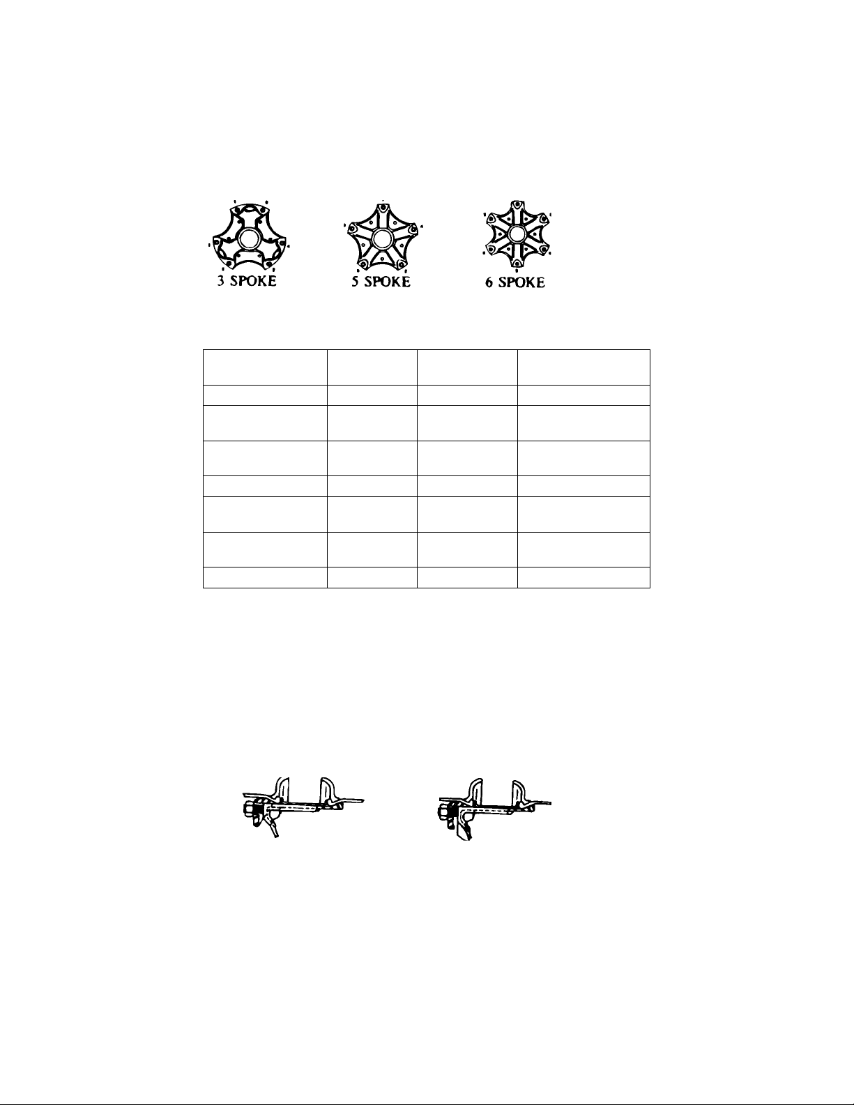
Spoke wheel installation and maintenance
RIM MOUNTING INSTRUCTIONS:
Rims must be correctly assembled, rim clamps must match the rim spacer width and rim clamp nuts must be
correctly tightened to assure maximum service life and maximum safety.
1. All parts must be clean, free of rust, dirt and paint..
2. Slide the inside rim over the wheel so the 28° mounting surfaces mate. Be sure the valve stem is pointing
out and is centered between two spokes.
3. Slide the rim spacer over the wheel and against the inner rim.
4. Slide the outer rim over the wheel. Be sure the valve system is pointing in and is centered between the
same spokes as the inner valve stem.
5. Install the rim clamps and nuts. Lightly tighten the rim nuts while rotating the wheel.
6. Tighten the rim nuts a quarter turn at a time in order shown until tightened to the correct torque.
Recommended Torque Dry: 200 to 250 Ft. Lbs.
- 20 -
Recheck rim clamps after first 50 to 100 miles of
service.
BRAKE DRUM
ASSEMBLY TORQUE FOR DRUM BOLTS
(Grade 5 or 8 Fasteners)
THREAD SIZE TORQUE
FT-LBS MIN
REQUIRED
FT-LBS MAX
1/2- 20 Rotate Belt 50 80
5/8-18
(Tapped Holes) Rotate Belt 150 200
5/8-18
(Thru Holes) Rotate Nut 75 100
3/4-10 Rotate Nut 130 165
3/4-16
(Wheels) Rotate Nut 175 200
3/4-16
(Hubs) Rotate Nut 100 225
1-14 Rotate Nut 175 225
Note: All Fastener parts must be clean and dry.
7. The rim clamp does NOT have to heel against the face of the spoke. If the rim clamp does have a heel,
the heel MUST NOT bottom out before reaching 80% of the recommended torque. DO NOT over
torque. All that is required to properly hold the rims is 200 to 250 Ft. Lbs.
CORRECT CORRECT
HEEL-LESS CLAMP HEEL TYPE
CLAMP
Recommended Torque 200 to 250 ft. Ibs.
Over Torque Can Deform Rim Spacer and Damage Back Flange
8. Check alignment. Place a block of wood or object on the floor and rotate wheel. If variation exceeds
118", the rim is not properly mounted. To correct, loosen the nut on the side with the greatest deviation
and tighten the nuts opposite. Recheck the torque as shown in step 6.
9. Recheck the rim clamps after the first 50 to 100 miles of service.
This manual suits for next models
1
Table of contents


