Thomas PROTOUGH 900 User manual

Owner’s / Operator’s
and Parts Manual
Publication No. 50008
November 2004
S/N T9000101 onward
900

THOMAS EQUIPMENT LIABILITY WARRANTY
THE WARRANTY IS THE ONLY OBLIGATION OF THOMAS OR A
THOMAS DEALER TO THE PURCHASER OR ANYONE ELSE CONCERNING
A PRODUCT, ITS SERVICE, ITS USE OR PERFORMANCE OR ITS LOSS OF
USE OR FAILURE TO PERFORM. NEITHER THOMAS NOR A THOMAS
DEALER HAVE MADE AND NEITHER WILL MAKE ANY OTHER
EXPRESSED OR IMPLIED REPRESENTATION, WARRANTY OR AGREE-
MENT CONCERNING A PRODUCT, NEITHER THOMAS NOR A THOMAS
DEALER HAVE MADE OR WILL MAKE ANY REPRESENTATION, WAR-
RANTY OR AGREEMENT CONCERNING A PRODUCTS MERCHANTABILI-
TY OR OTHER QUALITY, ITS SUITABILITY FOR PURCHASER’S PURPOSE
(EVEN IF APURCHASER HAS INFORMED THOMAS OR ATHOMAS DEAL-
ER OF THAT PURPOSE), ITS DURABILITY, PERFORMANCE OR OTHER
CONDITION.
EVEN IF THOMAS OR A THOMAS DEALER WAS ADVISED OF THE
POSSIBILITY OF SUCH LOSS, NEITHER THOMAS NOR A THOMAS DEAL-
ER WILL BE LIABLE TO PURCHASER OR ANYONE ELSE FOR ANY INDI-
RECT, INCIDENTAL CONSEQUENTIAL, PUNITIVE, ECONOMIC, COMMER-
CIAL, OR SPECIAL LOSS WHICH IN ANY WAY ASSOCIATED WITH A PROD-
UCT. THIS INCLUDES ANY LOSS OF USE OR NON-PERFORMANCE OF A
PRODUCT, ANY REPLACEMENT RENTAL OR ACQUISITION COST, ANY
LOSS OF REVENUE OR PROFITS, ANY FAILURE TO REALIZE EXPECTED
SAVINGS, ANY INTEREST COSTS, ANY IMPAIRMENT OF OTHER GOODS,
ANY INCONVENIENCE OR ANY LIABILITY OF THE PURCHASER TO ANY
OTHER PERSON.
PURCHASER MAY NOT ATTEMPT TO ENLARGE ITS RIGHTS UNDER
THE WARRANTY BY MAKING CLAIM, FOR INDEMNITY, FOR BREACH OF
CONTRACT, FOR BREACH OF COLLATERAL WARRANTY, FOR A TORT
(INCLUDING NEGLIGENCE, MISREPRESENTATION OR STRICT LIABILI-
TY) OR BY CLAIMING ANY OTHER CAUSE OF ACTION.
THE WARRANTY IS A CONDITION OF SALE OF THE PRODUCT TO
THE PURCHASER AND WILL THEREFORE APPLY EVEN IF THE PUR-
CHASER ALLEGES THAT THERE IS A TOTAL FAILURE OF THE PRODUCT.
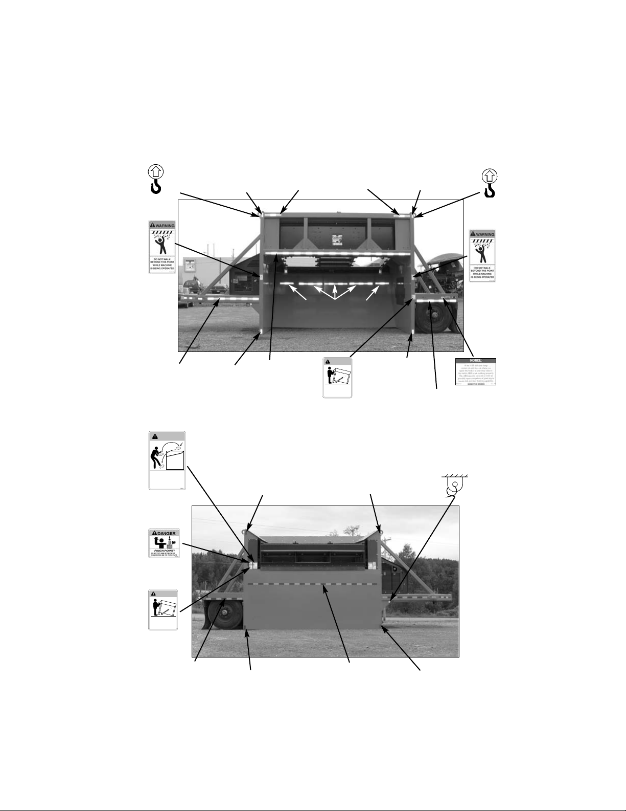
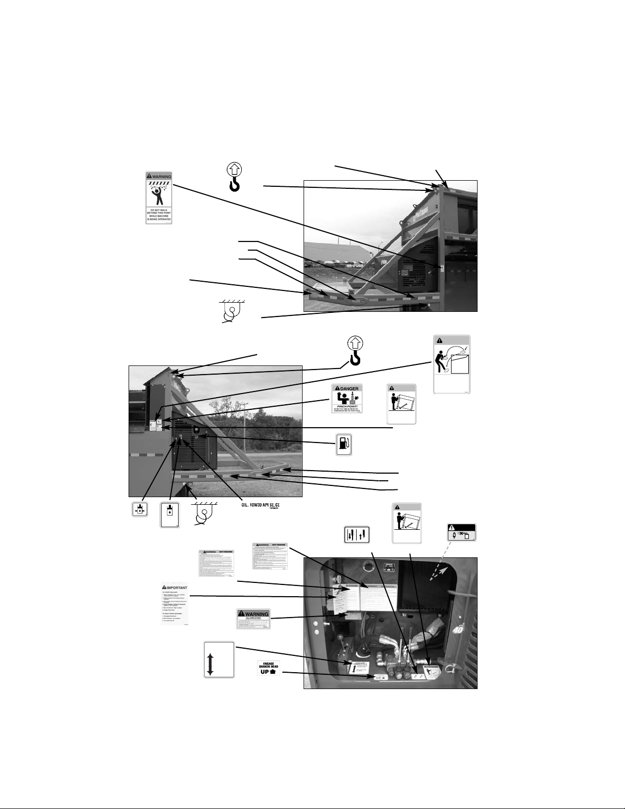
N.B. Read and practice your Thomas operating and servicing instructions. Failure
to do this may void the warranty.
PUBLICATION NUMBER 50008
© Thomas Equipment Inc.
Printed in Canada

INDEX
1. SAFETY PRECAUTIONS
General Instruction............................................................................... 1.1
Decals ................................................................................................... 1.2
Orientation / Access ............................................................................. 1.3
2. CONTROLS
Engine Controls.................................................................................... 2.1
Hydraulic Controls ............................................................................... 2.2
Pneumatic Controls .............................................................................. 2.3
Axle Stop Controls............................................................................... 2.4
3. OPERATION
Pre-Start Inspection.............................................................................. 3.1
Starting Instructions ............................................................................. 3.2
Shut Down Procedure .......................................................................... 3.3
Set-up ................................................................................................... 3.4
Operating Procedures ........................................................................... 3.5
Transporting ......................................................................................... 3.6
4. MAINTENANCE
Service Access...................................................................................... 4.1
Preventative Maintenance Schedule .................................................... 4.2
Daily Service........................................................................................ 4.3
50 Hour Service ................................................................................... 4.4
300 Hour Service ................................................................................. 4.5
900 Hour Service...................................................................................4.6
As Required Service............................................................................. 4.7
Battery Maintenance and Boosting .......................................................4.8
Electrical Schematic - Chassis ............................................................. 4.9
Electrical Schematic - Engine............................................................ 4.10
Hydraulic Schematic .......................................................................... 4.11
Pneumatic Layout............................................................................... 4.12
Troubleshooting...................................................................................4.13
5. SPECIFICATIONS
Dimensional Specifications.................................................................. 5.1
Performance Specifications.................................................................. 5.2
Fastener Torque Specifications .............................................................5.3
6. REPLACEMENT SCREENS
Screen Selection Tips ........................................................................... 6.1
Replacement Screen Information......................................................... 6.2
7. PARTS
1

1. SAFETY PRECAUTIONS
The following precautions are suggested to help prevent accidents.
A careful operator is the best operator. Most accidents can be avoided by observing
certain precautions. Read and take the following precautions before operating this
machine to help prevent accidents. Equipment should be operated only by those
who are responsible and instructed to do so.
1.1 GENERAL INSTRUCTIONS
1. Read this manual carefully before using the machine. Working with unfamiliar
equipment can lead to accidents.
2. Do not allow anyone to ride on the machine when being towed.
3. Make sure all safety and instruction decals are in place, and legible. (See
section 1.2).
OPERATING THE MACHINE
1. Always tow the machine at speeds compatible with safety, especially when
operating over rough ground, crossing ditches or turning.
2. Use care when operating on steep grades to maintain proper stability.
3. Be careful when towing through door openings or under overhead objects.
Always make sure there is sufficient clearance.
4. When travelling on public roads, know the local rules and regulations and
make sure your machine is equipped with the proper safety equipment.
5. Watch out for overhead and underground high-voltage electrical lines when
operating the machine.
6. Always park the machine on firm level ground. If necessary, prepare a level
area to operate the machine from.
7. Be watchful of bystanders when starting or during operation.
8. Wear protective clothing such as safety eye wear, hearing protection, steel toe
foot wear, gloves and hard hats.
9. Never attempt to load the machine in excess of capacity.
10. Assure all hydraulic controls are functioning properly, as well as safety devices
are installed and functioning at all times.
11. Never run the engine in a closed building without adequate ventilation, as the
fumes can cause death.
12. Never go under the machine while it is operating.
13. If product is lodged in wire cloth, remove the affected screens from the
machine.
2

1. SAFETY PRECAUTIONS
MAINTENANCE
1. Stop the engine before performing any service on the machine.
2. Never refuel the machine while smoking or with the engine hot or running.
3. Replace all missing, illegible or damaged safety and warning decals. See
section 1.2.
4. Do not modify or alter, or permit anyone to modify or alter this machine or any
of its components or machine functions.
5. Do not bypass the safety systems. Consult your Thomas Equipment Dealer if
your safety system is malfunctioning.
6. Do not make mechanical adjustments while the machine is in motion or when
the engine is running.
7. Do not attempt to repair or tighten hydraulic lines when the system is under
pressure. Escaping fluid under pressure can penetrate the skin and cause
serious injury or death.
8. Whenever replacing pivot pins, always use a brass drift and hammer. Failure to
do so could result in injury from flying metal fragments.
9. The cooling system operates under pressure which is controlled by the radiator
cap. It is dangerous to remove the cap while the system is hot. Allow the
engine to cool before removing the radiator cap.
10. Wear protective clothing such as safety eye wear, hearing protection, steel toe
foot wear, gloves and hard hats.
11. The engine RPM (speed), is preset from the factory. Changing the preset speed
may cause severe damage to the shaker components, and will void your
warranty.
12. Battery gas can explode. Keep sparks and flames away from batteries. Never
short the battery terminals to check charge. Use a voltage meter or hydrometer.
13. Sulfuric acid in battery electrolyte is poisonous. Fill batteries in a well
ventilated area. Wear eye protection and rubber gloves. Avoid breathing fumes
when charging or electrolyte is added.
14. For securing and towing instructions, refer to sections 3.6.
15. Dispose of waste responsibly. Improper disposal of waste can harm the
environment and ecology. Contact your local environmental agency for proper
waste disposal procedures.
Read this manual completely before
attempting to operate this machine.
IMPORTANT
Do not operate this machine if any
protective guards are missing, or
have been removed.
WARNING
3

1. SAFETY PRECAUTIONS
1.2 DECALS
4
Amber Reflective Tape
#46155
T90106
T90107
Vehicle Identification Tag
#50186
#50259
#50260
TH41064
#41064
(Located on fan inside
engine compartment.)
Red/White Reflective Tape
#46152 (25”)
#45748
Amber Reflective Tape
#46155
Red/White
Reflective Tape
#46152 (31”)
Amber Reflective
Tape #46155
#50259
Red Reflective Tape
#46154
White Reflective Tape
#46153
#39191
#39192
Red/White Reflective Tape
#46152 (93”)
Red Reflective Tape
#46154
Red Reflective Tape
#46154
#50150

Red/White
Reflective Tape
#46152 (43.5”)
1. SAFETY PRECAUTIONS
1.2 DECALS
5
T90108
Amber Reflective
Tape #46155
Red/White Reflective
Tape #46152 (18”)
Red Reflective
Tape #46154
#39191
#50149
#50277
BEFORE LOWERINGTHIS
MACHINETO THE GROUND
LOOK TO MAKE CERTAIN
YOUR FEET ANDTHE FEET
OF OTHERS ARE NOT UNDER
ANY PARTOF THIS MACHINE!
WARNING
TH45413
#45413
#39191
Red Reflective
Tape #46154
Red/White
Reflective
Tape
#46152 (162”)
Amber
Reflective
Tape
#46155
#50149
Red/White
Reflective
Tape
#46152 (56”)
(18”) (31”) (18”)
Red/White Reflective Tape #46152
T90109
Red Reflective
Tape #46154
Amber Reflective
Tape #46155
BEFORE LOWERINGTHIS
MACHINETO THE GROUND
LOOK TO MAKE CERTAIN
YOUR FEET ANDTHE FEET
OF OTHERS ARE NOT UNDER
ANY PARTOF THIS MACHINE!
WARNING
TH45413
#45413
WARNING
STAND BACK
10 Feet (3Meters
)
ROCKS BOUNCE
OFFTHIS MACHINE!
;;
;;
;
;
;
TH45414
#45414
#46164
Red/White
Reflective Tape
#46152 (162”)
Red Reflective
Tape #46154
Red/White
Reflective Tape
#46152 (43.5”)
Amber Reflective
Tape #46155
#39192

1. SAFETY PRECAUTIONS
1.2 DECALS
6
T90110
T90111
T90112
Amber Reflective
Tape #46155
Red/White Reflective
Tape #46152 (18”)
#39191
Vehicle
Identification Tag
#50186
#39192
#50149
Red/White
Reflective Tape
#46152 (56”)
#46152 (white) (6”)
#46152 (25”)
Amber Reflective
Tape #46155 #39191
BEFORE LOWERINGTHIS
MACHINETO THE GROUND
LOOK TO MAKE CERTAIN
YOUR FEET ANDTHE FEET
OF OTHERS ARE NOT UNDER
ANY PARTOF THIS MACHINE!
WARNING
TH45413
#45413
WARNING
STAND BACK
10 Feet (3Meters
)
ROCKS BOUNCE
OFFTHIS MACHINE!
;;
;;
;
;
;
TH45414
#45414
#46164
Red/White
Reflective Tape
#46152 (31”)
#46152 (white) (6”)
#46152 (56”)
#39192
HYDRAULIC
HYDRAULISCH
HYRAULICO
HYDRAULIQUE
TH23307
#23307
TH23308
#23308
#38043
DIESEL
TH23310
#23310
BEFORE LOWERINGTHIS
MACHINETO THE GROUND
LOOK TO MAKE CERTAIN
YOUR FEET ANDTHE FEET
OF OTHERS ARE NOT UNDER
ANY PARTOF THIS MACHINE!
WARNING
TH45413
#45413
CAUTION
TH23312
#23312
#46369
#46370
#23325
OPERATION
AT IDLE
SHAKERHEAD
OPERATION
TH 50152
ENGINE
THROTTLE
STARTUP
ENGINE COOLDOWN
JACK OPERATION
#50152
#47437
#45902
TH046163
#46163
(next to air
breather)

T90078
1. SAFETY PRECAUTIONS
1.3 ORIENTATION / ACCESS
The following will familiarize you with the technical terms and location of
important components. Major components, control locations and indicator or
instruments can be located using the pictures provided.
Details of control operations and functions are explained in the Operations
Section 3.
7
Hydraulic fill
Top screen / plate
Bottom screen
Hopper
Hitch
Shaker deck /
head
Shaker deck / head
Engine / Hydraulic
compartment
Engine access
Control access
Oil fill
Muffler
Oil filter
Battery
Fuel filter
Oil level dip stick
Air cleaner
T90004
T90120
T90008
Fuel fill access

1. SAFETY PRECAUTIONS
1.3 ORIENTATION / ACCESS
(continued)
8
Shaker deck / head
Front cylinder jack
Rear suspension
stop lock
Counterweight
Shaker motor
Trailer Elecrical
Gladhand service
brake connector Gladhand emergency
brake connector
T90009
T90114
T90011
T90012
T90013
Instrument panel
T90014

2. CONTROLS
2. CONTROLS
Engine Controls ...................................... 2.1
Hydraulic Controls ................................. 2.2
Pneumatic Controls ................................. 2.3
Axle Stop Controls ................................. 2.4
9

2. CONTROLS
2.1 ENGINE CONTROLS
Instrument Panel: (T90014)
A. Oil pressure. This red indicator, when
on means that the engine is not running.
When it is flashing there is an oil pressure
problem and the engine will shutdown. If it
is off, the oil pressure is within limits.
B. Coolant temperature. This red indi-
cator will illuminate whenever the engine
coolant temperature exceeds the maximum
recommended level.
C. Charging. This amber indicator illu-
minates when there is an alternator problem.
When it is off the alternator is charging.
D. Glow plugs. This indicator will illu-
minate whenever the engine plow plug pre-
heaters are engaged. If it is flashing, the
preheating is done and the engine is ready
to start. When the indicator is off, the pre-
heat is off.
E. Hour meter. The hour meter mea-
sures actual engine operating hours.
F. Ignition switch. The ignition switch
controls engine preheat, start, run and stop
functions.
Throttle: (fig. T90015, T90016).
Pull throttle back for start and stop func-
tions (T90015). Push away from you and pull
into notch to engage operating speed
(T90016).
10
Instrument panel
Engine throttle control, idle position
Engine throttle control, run position
A
B
C
D
E
F
T90014
T90015
T90016

11
A
B
T90017
D
C
2. CONTROLS
2.2 HYDRAULIC CONTROLS
(fig. T90017)
A. Hydraulic lift for fifth-wheel hitch.
Pull lever towards you to raise the front of the
unit for fifth wheel engagement. Push away
from you to lower the front of the unit after
the tow vehicle is clear.
B. Hydraulic shaker head control. Push
to engage shaker head. Pull to stop shaker
head.
2.3 PNEUMATIC CONTROLS
C. Push the emergency brake valve to
release the parking brakes. The air tank must
still have pressure for the brakes to release
fully (T90017).
D. Turn the suspension dump valve to the
"Lower Position" or CCW (counter clock-
wise) 1/4 of a turn to release the air from the
suspension and lower the unit. This must be
done prior to engaging the Shakerhead.
(T90017).
If Toggle switch is used on unit; switch
suspension dump valve to the "Down
Position" or to the right, to release the air
from the suspension and lower the unit
(T90103). This must be done prior to engag-
ing the Shakerhead.
2.4 AXLE STOP CONTROLS
A. With the unit raised (air bags inflated),
remove the pin retaining the rear axle stop
handle. Move the axle stop handle to the ver-
tical or travel position (T90057). Install the
pin so the axle stop is locked (T90011).
Rear suspension
stop lock
T90011
The axle stop must be in the vertical posi-
tion before moving the unit.
IMPORTANT
T90057
Axle stop
travel position
T90103

12

13
3. OPERATION
3. OPERATION
Pre-Start Inspection ...................................... 3.1
Starting Instructions...................................... 3.2
Shut Down Procedure................................... 3.3
Set-up............................................................ 3.4
Operating Procedures ................................... 3.5
General .................................................3.5A
Loading Procedure ...............................3.5B
Removing Finished Material................3.5C
Removing Tailings ...............................3.5D
Screening Selection / Combinations.....3.5E
Transporting.................................................. 3.6

3. OPERATION
3.1 PRE-START INSPECTION
A daily inspection should be performed to
assure safe operation and minimal down time.
The daily maintenance should be performed
before start-up. See Section 4 for complete
details.
Engine:
1. Check the fuel level (refer T90018). Add fuel
if necessary. Make sure the filler cap is
secure.
2. Inspect fuel lines for leaks.
3. Check air cleaner restriction indicator, air
intake hoses and clamps. Assure everything
is tight and no hoses are chafed or have holes
in them (T90119).
4. Check engine oil level (T90120).
5. Check engine coolant level (T90120).
6. Check engine fan belt for cuts or wear
(T90120). If necessary, replace. Check ten-
sion and adjust as shown in Section 4.4D.
7. Check the hour meter reading. Have sched-
uled maintenance performed if required.
Refer to section 4 (T90014).
8. Verify compartment cover and doors are
closed and secured (T90008 & T90018).
14
Fuel level
gauge
Fuel fill
Check hour meter
T90014
T90120
T90018
T90119
Engine access
Control access
T90008
Access cover
Air Filter
Indicator
Engine access cover
Check

3. OPERATION
Hydraulics:
1. Check the fluid level. Add 10W30 motor oil
as required to bring fluid level in the middle
of the site gauge (fig. T90021). Make sure
the filler cap is secure.
2. Check all hydraulic hoses for chafing, bulges
and leaks. Replace immediately if defects are
found.
3. Verify hydraulic controls are in the neutral
position before starting the engine.
Shakerhead:
1. Check shaker suspension mounting hardware
for tightness (fig. T90023). Follow the proce-
dure in section 4.
2. Check shaker suspension mounts for cracks
(T90023). If cracks are found, consult your
local dealer.
3. Verify there is no debris on the shaker
screens and check for bystanders before
start-up.
4. Check the shaker screens and holddown
mounting hardware for proper tension (fig.
T90082 & T90013). See section 4.
Never repair or tighten hydraulic hoses or
fittings while the machine is running. Fluid
under pressure can penetrate the skin and
cause serious injury.
WARNING
Verify there is no debris on the shaker
screens and check for bystanders
before start-up.
WARNING
15
Grease bearings
Check bolts
Low level
Check bolts
Operating level
T90021
T90022
T90023
Shaker deck / head
T90013
Holddown T90082
Holddowns

3. OPERATION
3.2 STARTING INSTRUCTIONS
1. Perform the pre-starting inspection at
the beginning of this section.
2. Ensure the hydraulic controls are in the
neutral position (T90059).
3. Place the engine throttle control in the
low idle position (T90059).
4. Make sure bystanders are clear of area.
5. Preheat the engine glow plugs, turn the
ignition key counter clockwise, for 10
seconds (T90014a).
6. Engage the engine starter by turning the
ignition key fully to the clockwise posi-
tion (T90014b). Release when the
engine has started.
Do not engage the starter for more
than 15 seconds intervals. Repeat the
preheat procedure if the engine fails to
start. Allow the starter to cool to
ambient temperature after 3 consecutive
starting attempts. Failure to do
so may cause premature starter
and / or engine stop solenoid failure.
IMPORTANT
This engine is equipped with glow plug
type preheaters. Do not use ether or high
energy fuels to assist starting. Severe
engine damage may result.
CAUTION
16
Hydraulic controls to neutral
Throttle to idle
Preheat
engine glow
plugs
Engage
starter
T90014a
T90014b
T90059

3. OPERATION
3.2 STARTING INSTRUCTIONS
(continued)
7. Allow the engine to warm up 15 min-
utes at the idle position before operat-
ing at the normal operating speed.
8. Check the instrument panel gauges and
indicators for normal operation. Shut
the engine off immediately if warning
indicators are illuminated.
3.3 SHUT DOWN PROCEDURE
1. Make sure the shakerhead control lever
is in the neutral position and the shak-
erhead has stopped.
2. Move the throttle control to the idle
position and allow the engine to cool
for approximately 2 minutes.
3. Turn the ignition key counter clockwise
to the stop position.
4. Clear any debris that may still be stuck
to the shaker screens.
The engine idle position is
used for engine start up,
cool down and jack operations. DO NOT
operate at high idle
settings while performing
these operations. Damage or injury
may occur to the machine and/or
the operator.
WARNING
Follow the operation procedures in Section
3.4 before engaging the shakerhead.
IMPORTANT
This machine is a equipped with an engine
monitoring system that will shut down the
engine whenever engine oil pressure is too
low, or coolant temperature is too high.
The warning lights illuminate to notify
whenever a problem occurs. Have the
problem diagnosed and repaired before
further operation.
IMPORTANT
17
Allow the engine to warm
approximately 15 minutes before engaging
the shaker control. If the engine labors
when trying to engage the shakerhead,
allow the engine to warm an additional 5
minutes, then try again.
IMPORTANT

3. OPERATION
3.4 SET-UP
Follow the pre-starting inspection and
start-up instruction previous to this section.
The machine must be operated on a level
surface. If necessary, grade an area to
accommodate.
Make sure you leave adequate room for
maneuvering equipment around the
machine to remove tailings.
For efficient cycle times, keep the stock
piles as close as possible to prevent exces-
sive travel times.
1. Remove axle stop control pin and repo-
sition lever to operating position, rein-
stall safety pin (T90057 & T90011).
2. Start the engine and operate at the idle
position (T90075).
3. Disconnect both gladhand connections
and unplug the electrical harness from
the unit before moving the tow vehicle
(T90074 & T90009).
18
Set up at idle speed
T90075
T90009
T90011
Operating position
Gladhands
Disconnect electrical
T90072
T90057
T90074
Dump valve in
‘lower’ position
Non-operating
position
Table of contents
Popular Utility Vehicle manuals by other brands

Charles Machine Works
Charles Machine Works Ditch Witch PR482 Operator's manual

Sauber
Sauber 1521 Operation and maintenance manual

Polaris
Polaris ACE 900 SP owner's manual

Morooka
Morooka MST-800VD Operation & maintenance manual

Club Car
Club Car TURF 1 2001 owner's manual

Yamaha
Yamaha RHINO YXR45FW owner's manual