PreciseFit DC0001-N User manual

mPreclseFilt.
II E ITm[.l$TErl FOTT THE *,CIg
Precise Fit Trusted for the Job & PF Design@ is a registered trademark of LF, LLC.
All Rights Reserved.
ITEM #A153730
1O GU. FT. STEEL UTILITY DUMP CART
Pu rchase Date
MODEL # DCOOO1 -N
@
ATTACH YOUR
Serial Number
RECEIPT HERE
Questions, problems, missing parts? Before returning to your retailer, call our customer
service department at 1-800-643-0067, 8 a.m. - 6 p.m., Monday - Thursday; 8 a.m. - 5 p.m.,
Friday, EST.

TABLE OF CONTENTS
A SAFETY INFORMATION
SAFETY RULES
Remember, any power equipment can cause injury if operated
understand how to operate the equipment. Exercise caution atimproperiy or if the user does not
alltirnes when using power equipment
Look for this symbol to point out
important safety precautions. lt
means -ATTENTION! Become alert!
Your safety is involved.
CAUTION : Vehicle braking and
stability may be affected with the
addition of an accessory or an
attachment. Be aware of changing
conditions on slopes.
1. Read this owner's manual before attempting to assemble or operate the cart.
2. Read the vehicle owner's manual and know how to operate your tractor before using the cart
attachment.
3. Do not at any time carry passengers in this cart. lt has not been designed to carry passengers.
4. Never allow children to operate the tractor or the cart attachment.
5. Do not allow adults to operate the tractor or cart attachment without proper instructions.
6. Always begin with the transmission in first (low) and gradually increase speed as conditions
permit.
7. Tow the cart at reduced speed over rough terrain and hillsides or near creeks and ditches to
prevent tipping over and loss of control. Do not drive too close to a creek or ditch.
8. Attaching this cart may affect the vehicle braking and stability. Do not fill cart to maximum weight
capacity without checking the capability of the towing vehicle to safely pull and stop with the cart
attached.
9. Do not tow this cart on highways or on public thoroughfares.
10. Maximum towing speed is 10 mph.
PACKA&ffi CON-T#NT$
ilry r^G
LilL| vR
g-t
O1\
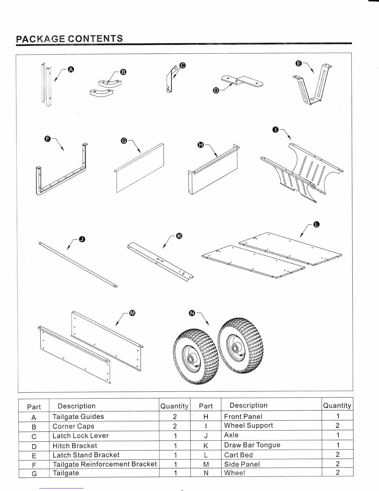
Pa rt Description Q u a ntity Part Description Q u a ntity
ATailgate Guides 2HFront Panel 1
BCorner Caps 2Wheel Su pport 2
CLatch Lock Lever 1JAxle 1
DH itch B racket 1KDraw tsar Tongue 1
ELatch Stand Bracket tlILCart Bed 2
FTa Igate Reinforcement B racket 1F.d Side Panel 2
GTa lgate 1NWh**l 2
HARDWARE PACK CONTENTS
Part
(E
Description
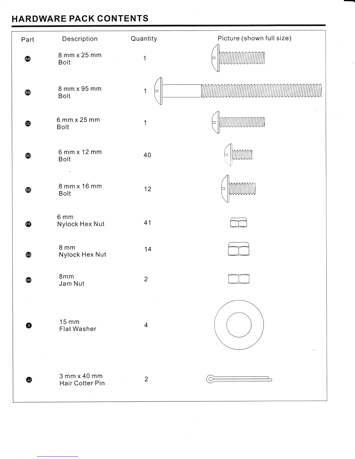
8mmx25mm
Bolt
8mmx95mm
Bolt
6mmx25mm
Bolt
6mmx12mm
Bol:
8mmx16mm
Bolt
6mm
Nylock Hex Nut
8mm
Nylock Hex Nut
Bmm
Jam Nut
Quantity
1
Pictu re (shown fu ll s tze)
@
@
@40 /T)
L 1il111?,11fr
\Lr",*"
A
Ftffi
Vffi
m
rt
@12
(D 41
14
@
@
o15 mm
Flat Washer
@3mmx40mm
Hair Cotter Pin
U
2
4

-l
Part Description QuantitY Picture (not shown full size)
@ Hair Cotter Pin
(D SPring @
M
w
4
@ 3[H::Jffiench 1
1@ Spring AssemblY Tool 1
@ Hitch Pin
PREPARATION
Before beginning assembly or operation of product, make sure all parts are present. Compare parts
with package contents list and diagram above. lf any part is missing or damaged, do not attempt to
assemble or operate the product. Contact customer service for replacement.
Estimated assembly time: 120 minutes.
Tools Required for AssemblY:
6 mm & 8 mm Open-end wrench (included) O=
Spring assembly tool (included)
Phillips screwdriver (not included)
Adjustable wrench (not included)
ASSEMBLY INSTRUCTIONS
-{
f-Yl
(c=-AJ
ffi
CAUTION
Do not leave the cart unattended in upright position
during assembly. A falling cart can cause personal
injuryl Pay close attention to the stability of the cart
while it remains in an upright position, For stability,
assemble on a smooth, level surface.
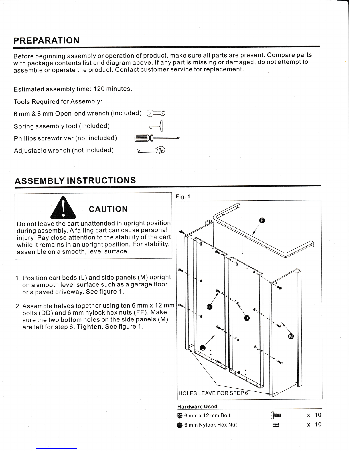
1 , Position cart beds (L) and side panels (M) upright
on a smooth level surface such as a garage floor
or a paved driveway. See figure 1.
2. Assemble halves together using ten 6 mm x 12mm
bolts (DD) and 6 mm nylock hex nuts (FF). Make
sure the two bottom holes on the side panels (M)
are left for step 6. Tighten. See figure 1 .
Fig. 1
HOLES LEAVE FOR STE}}
Hardware Used
@ 0 mm x12 mm Bolt
e) 6 mm Nylock Hex Nut @
Ex
x
10
10
/
oc
\c
-t\ \o..
\e
(D
o
-o
t\\
@

Fig. 2GUIDE CHANNELS
FACING FRO
3. Position the tailgate reinforcement bracket (F) on
outside of cart as shown in figure 2. Assemble to
the bottom of the cart body using six 6 mm x 12 mm
bolts (DD) and 6 mm nylock hex nuts (FF). See
figu re 2.
4. Position the tailgate guides (A) on the inside of
the cart body with guide channels facing front as
shown in figu re 2. Assemble using four 6 mm x 12
mm bolts (DD) and 6 mm nylock hex nuts (FF).See
figure2.
@ 0 mm x12mm Bolt
@ 6 mm Nylock Hex Nut (@
ffi x 10
x 10
5. Carefully reverse the
it rests on the tailgate
shown in figure 3.
position of the cart so that
rei nforcement bracket, os
6. Assemble the front panel (H) over the end of the
cart using fourteen 6 mm x 12 mm bolts (DD) and
6 mm nylock hex nuts (FF) as shown in figure 3.
7. Assemble two corner caps
of the cart using four 6 mm
6 mm nylock hex nuts (FF).
(B) to the front corners
x 12 mm bolts (DD) and
Tighten. See figure 3.
8. Attach two 6 mm x 12 mm bolts
nylock hex nuts (FF) to the two
cart. Tighten. See figure 3.
(DD) and 6 mm
rear corners of the
@0mmx12mmBolt
@ 6 mm Nylock Hex Nut @
mx20
x20
Fig.3
@- -t''
,€" \
/.k
L{o
o
Hardware Used
Hardware Used _
l
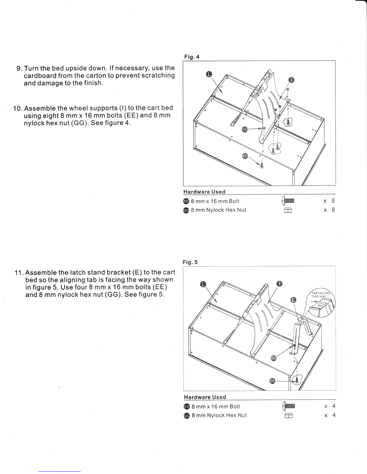
9. Turn the bed upside down. If necessary, use the
cardboard from the carton to prevent scratching
and damage to the finish.
10. Assernble the wheel supports (l) to the cart bed
using eight I mm x 16 rnm bolts (EE) and 8 mm
nylock hex nut (GG). See figure 4.
11 . Assemble the latch stand bracket (E) to the cart
bed so the aligning t3b is facing tl'te way shown
in figure 5. Use four 8 mm x 16 mrn bolts (EE)
and 8 mm nylock hex nut (GG). See figure 5.
GD g mm x 1G mm Bolt
@ 8 mffl Nylock Hex Nut @
ffi x8
xB
Hardware Used
@Ammxl6mmBolt
G& 8 mnn Nylock Hex Nut (@
ffi x4
x4
)I r i-
l1
t;
G
Fig.4
l-tandwai'e Used
Frg. 5
\\
N

12. Place the latch lock lever (C) through the slot in
the draw bar tongue (K) as shown in figure 3.
Assemble the 8 mm x 95 mm bolt (BB) through
the tongue, the lever and two 8 mm jam nuts (HH)
(one on each side of the lever). Assemble the 8
mm hex lock nut (GG) onto the end of the bolt
and tighten so that the bott can still rotate freely.
Tighten the two jam nuts (HH) against the sides
of the lever, centering it in the slot. See figure 6.
13.Attach the spring (LL) to the end hole in the latch
lock lever (C) and to the center hole in the draw
bar tongue (K) with spring assembly tool (N N ),
as shown in figure 6.
l4.Assemble the end of the hitch bracket (D)
(smaller hole) through the slot at the front of the
draw bar tongue (K). Fasten it to the tongue
using the 8 mm x25 mm bolt (AA) and 8 mm
nylock nut (GG).
15. Assemble the hitch pin (OO) to the hitch bracket
(D) by using the hair cotter pin (KK) .
See figure 7.
CD
@
@
@
8 mm x 95 mm Bolt
8 mm Nylock Hex Nut
8mm Jam Nut
S pring
x1
x1
x2
x1
@ A mm x25 mm Bolt
@ I mm Nylock Hex Nut
@ nair Cotter Pin
@ Hitch Pin
x1
x1
x1
x1
Fig. 6
Hardware Used
Fig.7
Hardware Used
TOP.VIEW
BOTTOM-VIEW
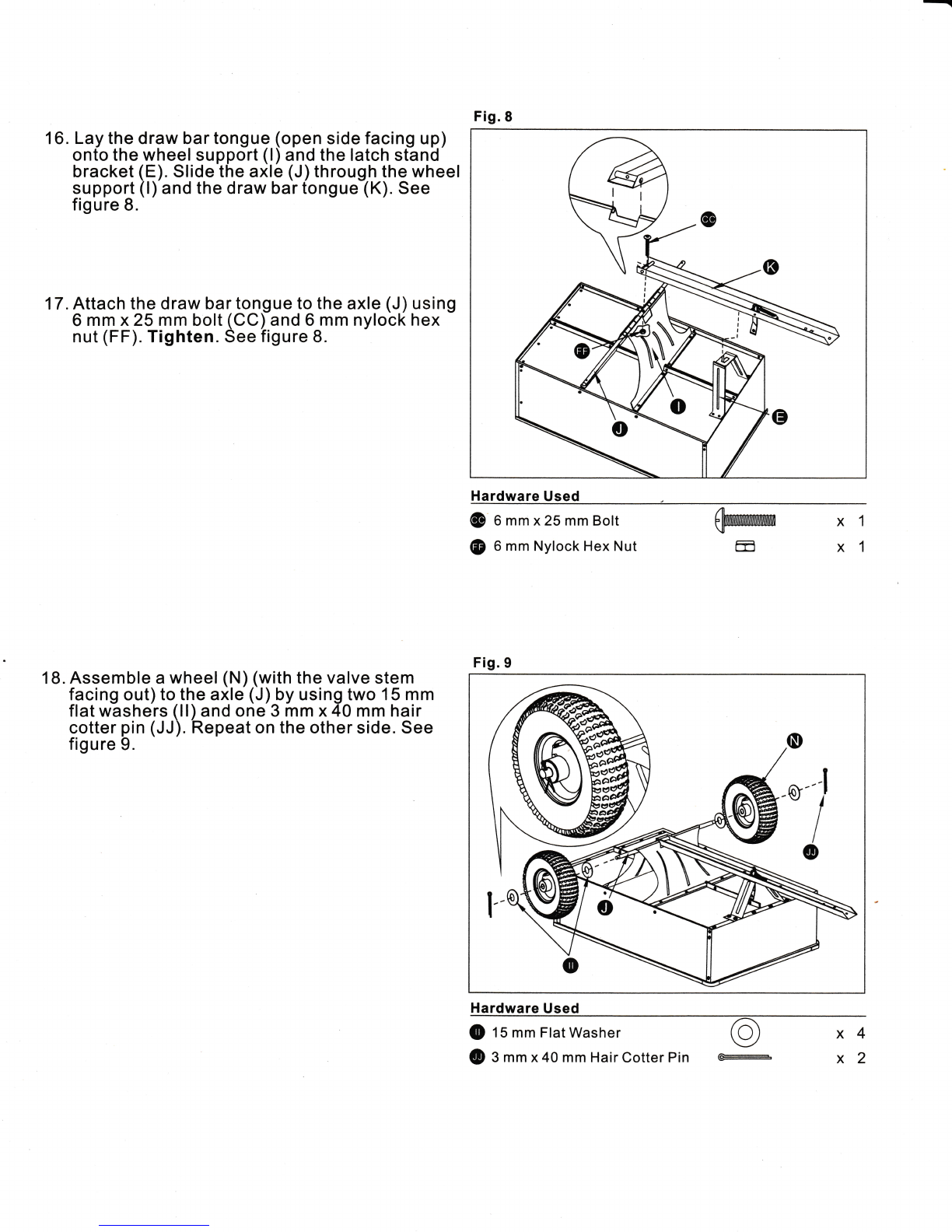
Fig.8
Lay the draw bar tongue (open side facing up)
onto the wheel support (l) and the latch stand
bracket (E). Slide the axle (J) through the wheel
support (l) and the draw bar tongue (K). See
figure 8.
17. Attach the draw bar tongue to the axle (J)
6 mm x 25 mm bolt (CC) and 6 mm nylock
nut (FF).Tighten. See figure 8.
18. Assemble a wheel (N) (with the valve stem
facing out) to the axle (J) by using two 15 mm
flat washers (ll) and one 3 mm x40 mm hair
cotter pin (JJ). Repeat on the other side. See
figure 9.
16.
usi ng
hex
Hardware Used x1
x1
qWUWWffWn
E
@ O mm x25 mm Bolt
@ 6 mm Nylock Hex Nut
Hardware Used
O 15 mm FlatWasher O x 4
@ S mm x40 mm HairCotter Pin F x 2
Fig. 9
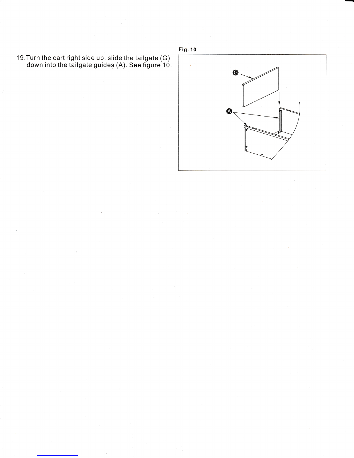
19.Turn the cart right side up, slide the tailgate (G)
down into the tailgate guides (A). See figure 10.
Fig. 10

OP E RATION I N STRU CTIONS
OPERATION
CAUTION: Vehicle braking and
stability may be affected with the
addition of an accessory or an
attachment. Be aware of changing
conditions on slopes.
1 . Refer to the vehicle owner's manual for
instructions on safe operation on slopes.
2. For best handling and traction, distribute the
weight of the load evenly in the cart.
3. Always test to make sure your tractor has
adequate towing and braking capabilities
whenever hauling a substantial amount of
weight in your cart. Use extra caution when
operating on slopes. 3.
CAUTION: Do not exceed the
towing capacity of the vehicle.
Follow any weight limitations
listed in the veh icle operator's
man ual.
4.To dump material from the cart, remove the
tailgate by Iifting it straight up and out from
between the guides. Release the spring latch
on the tongue by pulling the latch tock lever
forward, away from the cart. The cart bed will
then tilt backwards to empty its contents. After
emptying, pull the front of the bed down toward
the cart tongue until the latch snaps into place.
Replace the tailgate if desired.
5. The maximum towing speed for this cart is 10
m ph.
GAUTION: To avoid possible
injury, before releasing the latch
be sure that no one is near the
ca rt.
MAINTENANCE
1. At the beginning of each season, lubricate
the latch, the latch pivot bolt, and the area
of the axle where the drawbar tongue pivots
with light machine oil.
2. Grease or oil the wheel bearings
periodically. Use automotive wheel bearing
type g rease o r 20 weig ht oil .
3. Keep tires filled to the recommended tire
pressure of 30 psi.
HOW TO LUBRIGATE YOUR WHEELS
To enhance the function and longevity of your
wheels, periodically Iubricate the beanings.
To lubricate, follow these steps:
Take off the wheels.
If you have a grease gun at hand, insert the
nozzle into the hub and inject 3-4 drops of
bearing type greasel ubricant onto the
opposite bearing. Make sure the wheel is
standing upright and the nozzle reaches
deep enough so the drops are squeezed on
the orbit of the opposite bearing.
lf you have no grease gun at hand, you can
also lu bricate you r wheels with a brush. Dip
a brush in bearing type g rease lu bricaht,
thread the brush into the hub till it reaches
the bearing on the opposite end of the hub.
Trace the orbit of the bearing to spread
lubricant evenly. To ensure the bearing is
soaked with enough lubricant, repeat 5-6
times.
Follow the same steps to iuOficate the
bearing on the other end of the hub on the
wheel.
Reattach the wheels.
2.
4.
5.
INSIDE VIEW OF
OPPOSITE BEARING
INSIDE VIEW OF
1.

I.YEAR LI tU ITE D WARRAN TY
The manufacturer warrants to the original purchaser for a period of one (1 ) year that this product is
free from defects in material and workmanship. Warranty is void if the product is used for commercial
purposes.
This warranty is not transferable and does not cover products soJd damaged or incomplete, sold "as
is," sold reconditioned or used as rental equipment. lt does not cover damage caused by misuse,
neglect, accident, alterations or use and maintenance other than that specified in the owner's
manual.
The manufacturer will provide replacement parts or rentace the unit at lts option. For warranty service
call customer service at 1-800-643-0067, 8:00 a.m. - 6 p.m. Monday - Thursday; 8:00 a.m. - 5 p'm.,
Friday, EST. DO NOT RETURN PRODUCT TO THE STORE.
The manufacturer will not be held liable for any direct, indirect, incidental or consequential damages.
Some states do not allow limitations on how long an implied warranty lasts, or the exclusion or
limitation of incidental or consequential damages, so the above limitations may not apply to you. This
warranty gives you specific rights, and you may also have other rights which vary from state to state'

EXPLOEDED VIEW
\I
M
ll"l
iil -@
li{
ll
!l"l
U
_ -(D
tn/
fll
@
@-. @-
\qr {
t&-/
\@
--j\I
I
I
lr'
o
,\
@r\
$
e)+
tl \
ll /ln
w/

t
I
!
I
t
REPLACEMENT PARTS LIST
For replacement parts, call our customer service department at 1-800-643-0067, 8 a.m. - 6 p.m.,
Monday - Thursday; 8 a.m. - 5 p.m., Friday, EST.
E
A-/
0r\
HDWE
Part Description Quantity Part Description Quantity
ATailgate Guides 2GTa ilgate 1
BCorner Caps 2HFront Panel 1
CLatch Lock Lever 1JAxle 1
D H itch B racket 1MSide Panel 2
ELatch Stand Bracket 1NWheel 2
FTai Igate Reinforcement Bracket 1HDWE Complete Hardware Pack 1
FPreciseFit
E!-JrnustED FoR THE JoB
Sqqow,m@' fA
$*vtr
Ei-'i--j {--------l
ffi <r-
km?&rddu4bE
t)*1;**"'*'*'lrn
lPE EY '
Printed in China

PLEASE DO NOT RETURN THIS PRODUCT TO THE STORE.
Our Gustomer Service Department can help with:
. Assembly or operation questions
o Missing or damaged parts
o Troubleshooting
For assistance, please call:
1-800-643-0067
8:00 am to 6:00
8:00 am pm, E.S.T, Monday r Thursday.
to 5:00 pm, E.S.T., Friday.
Table of contents
Popular Outdoor Cart manuals by other brands

SAW TRAX
SAW TRAX yel-Low Safety Dolly instruction manual

Metro DataVac
Metro DataVac Flo Series Operation manual

Gorilla Carts
Gorilla Carts GOR200B owner's manual

Reacha
Reacha DIY operating instructions

Gorilla Carts
Gorilla Carts GOR-2240DEC quick start guide

Wenger
Wenger Tourmaster Storage Cart owner's manual

Northern Tool and Equipment
Northern Tool and Equipment NTE200 owner's manual

Fantom
Fantom PROCART 340 Assembly manual

Winther
Winther 408 Assembly instruction

Black cat
Black cat MH1240 owner's manual

BGS technic
BGS technic 4102 quick start guide

Great day
Great day HNGC-350 Instructions for installation and use


