- 3 - - 4 -
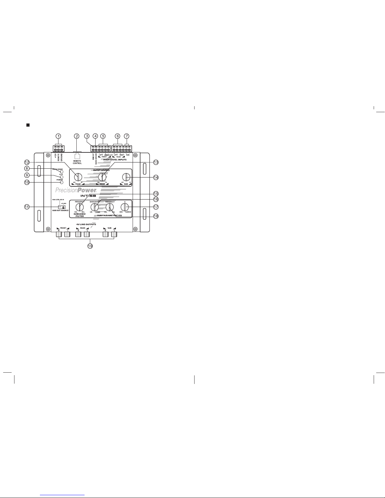
Functions AndOperations:
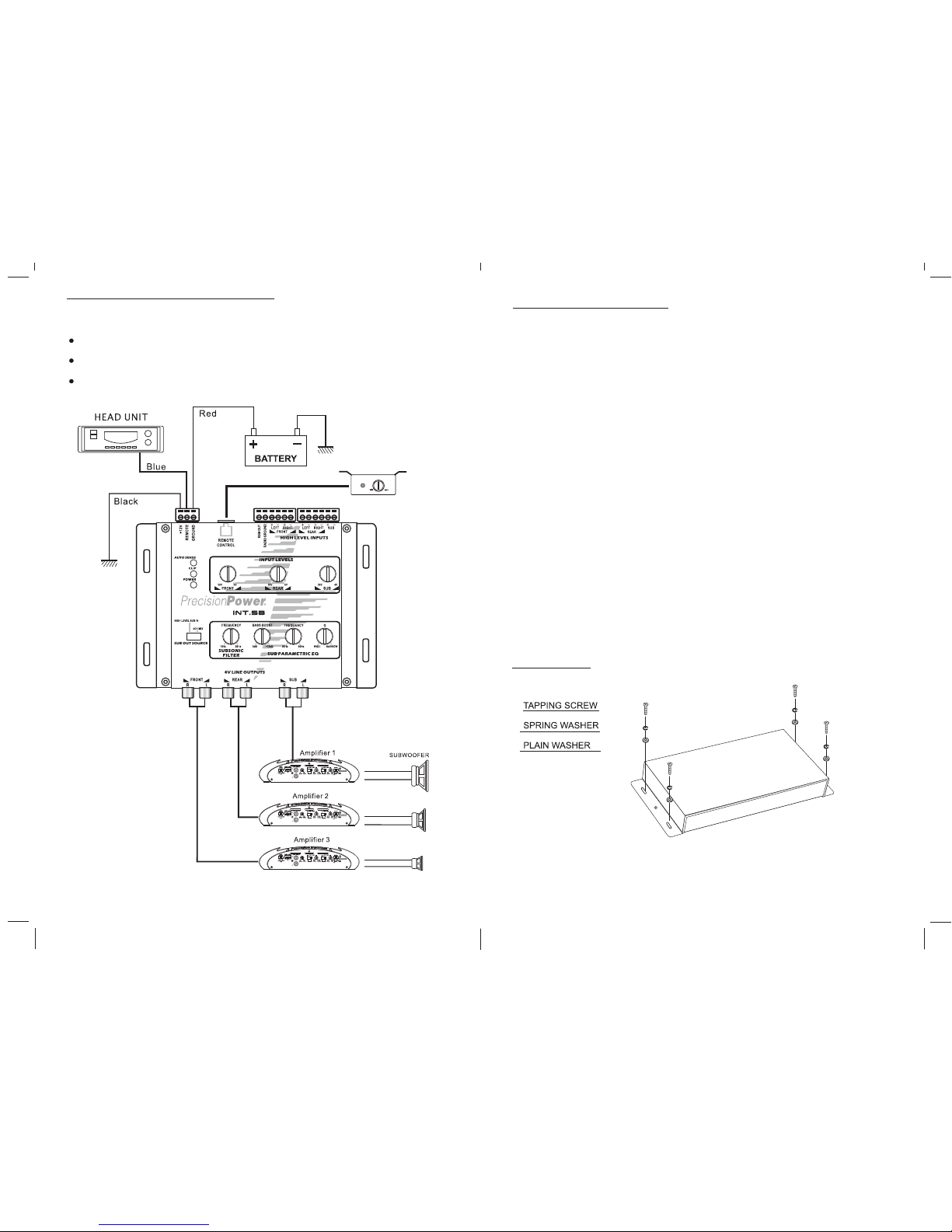
1. Power,Ground, & RemoteDisconnect: Secure +12V constantpower, ground,and factory
source unit remoteturn-on (if available)connections to theappropriate terminal ofthe
supplied disconnect plug.
2. Remote ControlModule Connection:Connect one end of the suppliedRemote Control
Module Cable tothis port. Theother end shouldconnect to theRemote Control Module.
3. Delayed RemoteTurn-On:Connect a lead to the remoteturn-on terminals ofthe other
components in the audio system. This remote turn-on has a built-in delayto eliminate
unwanted pops.
4. Radio Ground:Connecting a wirefrom this terminalto the Radio'sground wire willeliminate
ground loops andeliminate or greatlyreduce this typeof induced noise.
5. Front HighLevel Input:Connect the frontleft and frontright factory sourceunit speaker
level outputs tothe High LevelFront Input terminals.(consult the vehiclemanufacturer for
the correct factorysource unit wireconfiguration)
6. Rear HighLevel Input:Connect the rearleft and rearright source unitspeaker level outputs
to the High Level Rear Input terminals. (consult thevehicle manufacturer forthe correct
factory source unitwire configuration)
7. High LevelSubwoofer Input:Connect the subwoofersource unit speakerlevel outputs to
the High LevelSubwoofer Input terminals.If the factorystereo system doesnot have a
subwoofer and subwoofercontrol within thesource unit, setthe Subwoofer SourceSelector
to 4 Ch.Mix, eliminating theneed for aHigh Level SubwooferInput connection. See#11
Subwoofer Source Selectorbelow for furtherinformation.
8. Signal SenseIndicator: The Current SenseIndicator will illuminateif the processorhas
been activated byreceiving power fromthe remote input,or sensing audiosignal to the
high-level inputs. Signalsensing eliminates theneed to connectremote turn-on power. A
built-in delay preventsthe processor fromturning offbetween song tracks.The processor
remains active approximately1 minute afteraudio signal islost.
9. Clipping Indicator:The Clipping Indicatorwill illuminate ifthe Low LevelOutput signal
is clipped regardlessof voltage. Aclipped signal isnoticeable to atrained ear inthe form
of distortion, whichcan and willcause damage toall speakers.
10. Power Indicator:The Power Indicatorwill illuminate whenand while theunit is receiving
power.
11. SubwooferSource SelectorSet the SubwooferSource Selector toHigh Level SubIn if
the factory sourceunit has speakerlevel outputs andsource unit controlfor a factory
subwoofer. Connectthe factory sourceunit subwoofer speakerlevel outputs tothe High
Level Subwoofer Inputterminals. If thesource unit doesnot have subwoofercontrol or
dedicated subwoofer highlevel output wires,then set theSubwoofer Source Selectorto
4 Ch. Mix. The processor will now use thesignal from theFront & RearHigh Level
Inputs as thesubwoofer signal.
12. Front ChannelInput Sensitivity:Set the FrontChannel Input Sensitivityto closely match
the factory sourceunits maximum frontchannel output voltage.The minimum settingis 4V,
the maximum is30V. Youcan use theclipping indicator tohelp properly setthis control. If
the clipping indicatorlights up frequently, then turnthe control downa bit untilthe clipping
indicator remains off.
13. Rear ChannelInput Sensitivity:Set the RearChannel Input Sensitivityto closely match
the factory sourceunits maximum frontchannel output voltage.The minimum settingis 4V,
the maximum is30V. Youcan use theclipping indicator tohelp properly setthis control. If
the clipping indicatorlights up frequently, then turnthe control downa bit untilthe clipping
indicator remains off.
14. Subwoofer ChannelInput Sensitivity: Set the SubwooferChannel Input Sensitivityto
closely match thefactory source unitsmaximum front channeloutput voltage. Theminimum
setting is 4V, the maximumis 30V. You can usethe clipping indicatorto help properlyset
this control. Ifthe clipping indicatorlights up frequently, then turnthe control downa bit
until the clippingindicator remains off.
15. Subsonic FilterControl: Set the SubsonicFilter Control tothe desired subsonicfilter
frequency.The minimum frequencyis 15Hz, themaximum is 50Hz,Generally,subsonic
filters are setbetween 20-30Hz toavoid harmful lowfrequencies that willdamage sub-
woofers. The powerwasted on subsonicfrequencies will nowbe useful inthe audible
sub bass region.
16. Bass BoostLevel Control: This control allowsyou to set the amount ofboost desired.
Be careful notto overdrive thesubwoofer and payattention to theclipping indicator.
17. Boost QLevel: will increase ordecrease the bandwidthof frequencies boostedabove
and below the selected Bass Boost Frequency.The minimum settingof Narrow will
boost only asmall range offrequencies above andbelow the BassBoost Frequency,
while the maximumsetting of Widewill boost thelargest range offrequencies above
and below theBass Boost Frequency.
18. Bass BoostFrequency Control: The Bass BoostFrequency Control willselect the
desired frequency to be boosted. Theminimum frequency is30Hz and themaximum
is 80Hz.
19. Low-Level Front,Rear & SubwooferOutputs: RCA connections forLow-Level Front,
Rear, &Subwoofer Output signal.Use RCA cablesto connect theRCA outputs tothe
low-level inputs ofthe corresponding amplifier(s)if the sourceunit is equippedwith RCA
outputs.