TVC NFM3 User manual

The Validation Centre (TVC) Limited
Unit 15, Brinell Way, Great Yarmouth, Norfolk, NR31 0LU, UK.
01493 443800 01493 443900 [email protected] www.tvcalx.co.uk
NFM3
NOZZLE FLOW METER 3
INSTRUCTION MANUAL
V1.0

Page 1of 15
Contents
Section
Description
Page
1.0
Overview
2
1.1
Supplied items
2
1.2
Buttons and connectors
2
2.0
Operation
4 - 14
2.1
Warnings
4
2.2
Switch ‘On/’Off’
4
2.3
Gas selection
5
2.4
Flow measurement
6
2.5
Selecting measurement units (Advanced unit only)
6
2.6
Peak reset
7
2.7
Data logging (Advanced unit only)
7 - 9
2.8
Viewing logged files on NFM3 (Advanced unit only)
10 - 11
2.9
Quick-start operational flow charts
12 - 14
3.0
Battery charging
15
4.0
Additional information
15
4.1
Specification
15
4.2
Calibration
15
4.3
Disposal
15

Page 2of 15
1.0 Overview
1.1 Supplied items
1. NFM3
2. Battery charger
3. Battery charger mains lead
4. 16mm nozzle
5. 19mm nozzle
6. 22mm nozzle
7. Nozzle extension hose
8. NFM3 to PC USB interface lead (Advanced unit only)
9. NFM3 to TVC weld monitor interface lead (optional)
9
1
4, 5
& 6
2
8
3
7

Page 3of 15
1.2 Buttons and connectors
1. Quick-release connector flow inlet
2. Display
3. ‘Reset’ button for resetting peak gas flow value
4. ‘Print’ button (for use with TVC weld monitors)
5. ‘Up’ button for gas type selection
6. ‘Down’ button for gas type selection
7. Input and USB/TVC weld monitor output connector
8. Power switch
1
2
4
3
6
5
7
8

Page 4of 15
2.0 Operation
2.1 Operational warnings
The following MUST be read before operating the NFM3:
1. The NFM3 is designed for use on inert arc welding shielding and
back purging gases only.
2. Always ensure that the wire feed drive wheels are slackened off
so that welding wire cannot be fed through the NFM3.
3. When using on equipment with high frequency (HF) arc starting,
always ensure the HF is turned off.
2.2 Switching the unit ‘On’/’Off’
Switch the power switch (Item 7, Section 1.2) to the ‘On’ position.
The NFM3 LCD will illuminate and the software version number together with the model type
will be displayed for a few seconds the screen will then revert to the standard display layout.
Standard Start Up Display
Standard Main Screen
Advanced Start Up Display
Advanced Main Screen
!

Page 5of 15
2.3 Gas selection
The NFM3 has been programmed with nine gas mix selections, these are:
Gas
Additional
information
Code
Argon
Ar
Carbon Dioxide
CO2
Nitrogen
N2
Argon/Helium
mixes 0 –10%
Ar-He 10%
Argon/Helium
mixes 10 –30%
Ar-He 30%
Argon/Helium
mixes 30 –50%
Ar-He 50%
Argon/Helium
mixes 50 –70%
Ar-He 70%
Argon/Helium
mixes 70 –100%
Ar-He 100%
The NFM3 has a ‘button-lock’ feature to prevent accidental button presses which may change
the gas selection. To access the gas selection area, press and hold the ‘Up’button for 3
seconds.
Once the buttons are unlocked and functioning, use the ‘Up’ and ‘Down’ buttons (Items 3 & 4,
Section 1.2) to scroll between the available selections. The selected gas is displayed at the
bottom of the screen.
Standard Model
Advanced Model
Gas selection is displayed
at bottom of the screen
Gas selection is displayed
at bottom of the screen

Page 6of 15
2.4 Flow measurement
Select the required size nozzle (Items 4, 5 & 6, Section 1.1) and connect it to the NFM3 quick-
release fitting. If required, use the extension hose (Item 7, Section 1.1).
Insert the arc welding torch nozzle into the NFM3 nozzle, ensuring a good fit. Make sure the
NFM3 is unit switched ‘On’ and the correct gas type is selected.
Press the ‘Gas Purge’ button on the arc welding set. Once the flow has stabilised, read the
flow in Litres per minute on the NFM3 screen. Once the gas stops flowing, the NFM3 screen
will revert to the small screen and display the peak flow, this is indicated with a ‘PK’ next to
the flow reading.
Nozzle without Extension
Nozzle with Extension
2.5 Selecting measurement units (Advanced unit only)
The NFM3 Advanced has user selectable measurement units - metric (LPM), or imperial
(CFH).
To switch between measurement units, follow the steps below:
1. Connect the NFM3 Advanced to a laptop or PC.
2. Switch ‘On’ the NFM3 Advanced and allow to connect. The NFM3 screen will display
‘Connected to USB’.
3. From ‘My Computer’locate the NFM3 Advanced which will show up as an external
drive. Make a note of the drive identification letter.
4. Double-click the drive to open and navigate to ‘TVC Handheld-Date –Setter’and open.
5. Select the drive letter as noted in Step 3, above. Failure to select the drive will result
in no changes being made.
6. Select the measurement unit required.
7. Click ‘Program unit’. The NFM3 Advanced is now set to the selected measurement
unit.
8. Switch the NFM3 Advanced ‘Off’ and disconnect the USB lead.
9. Switch ‘On’the NFM3 Advanced and confirm the correct measurement unit has been
set.

Page 7of 15
2.6 Peak Flow Reset
To reset the peak flow before taking another reading, press the ‘Reset’button (Item 5, Section
1.2). The peak flow will immediately reset to zero, ready for the next reading to be taken.
2.7 Data logging (Advanced unit only)
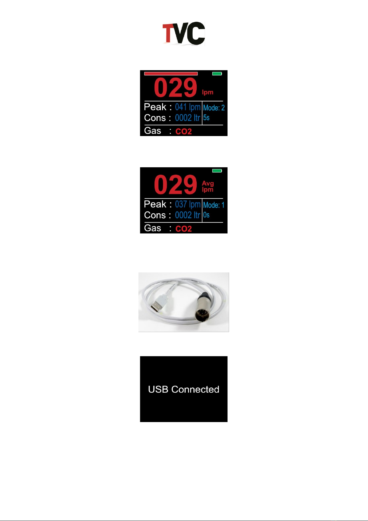
The optional data logging facility records flow results and surge data on the NFM3’s internal
memory. Recorded data is downloaded from the NFM3 via USB connection for direct import
into the included data viewing and reporting software.
There are two modes for data logging:
Mode 1: Quick screen print
Mode 2: Logs gas over a set time, taking a gas reading every 20 milliseconds
2.7.1 Mode 1
1. Switch ‘On’ the NFM3 Advanced unit.
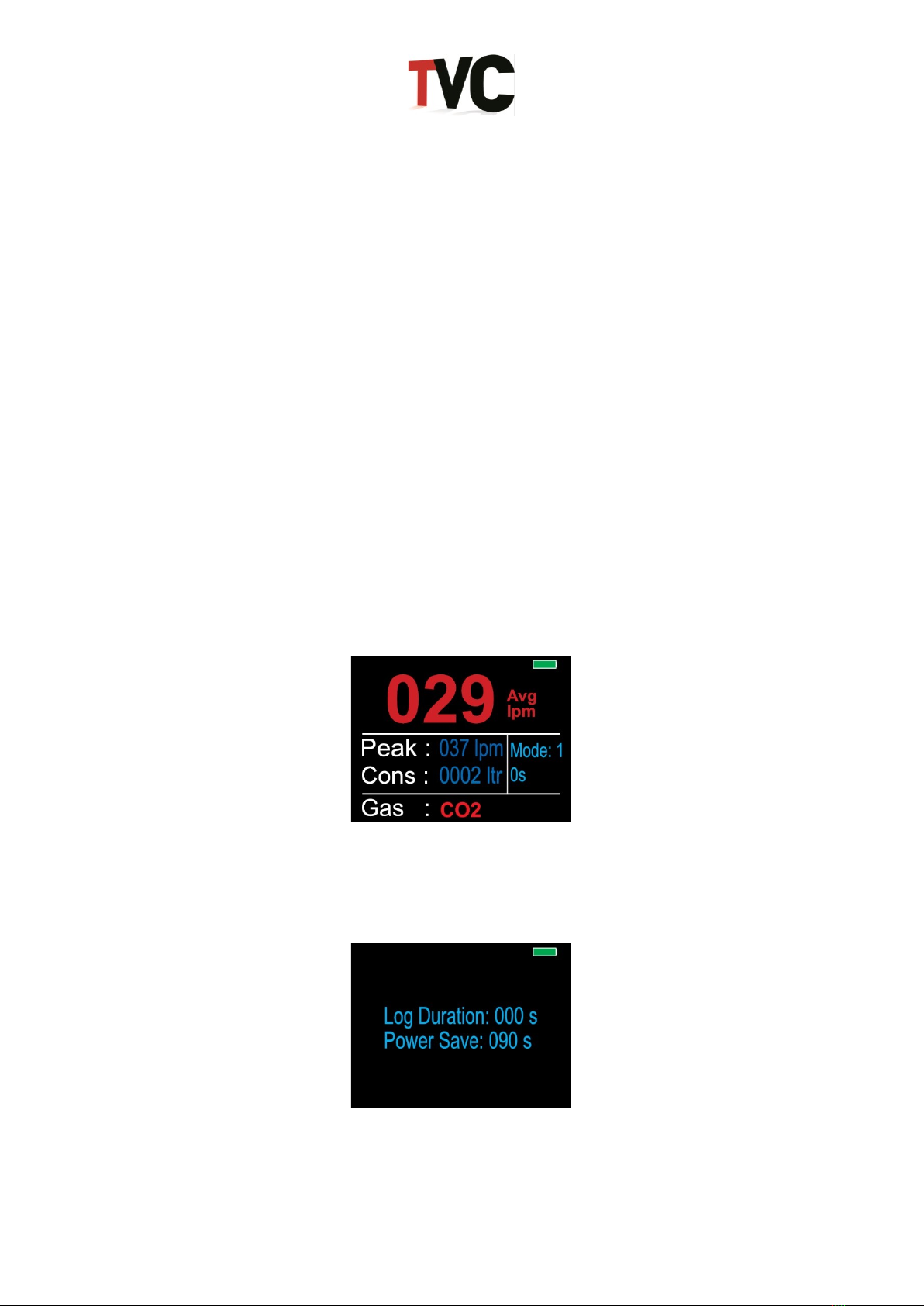
2. By default, the NFM3 is already in ‘Mode 1’. This provides a quick screen print of the
results.
3. Once the gas flow has been read, the screen will display the average gas flow, peak
flow and gas consumed. To log this on the NFM3’s internal memory, press the ‘Print’
button.
2.7.2 Mode 2
1. To set up the data logging function over a specific period, press the ‘Reset’ button until
the setup screen is displayed.

Page 8of 15
2. Using the ‘Up’and ‘Down’buttons, set the data logging duration.
3. Press ‘Reset’ to return to the main screen. The unit will now be in ‘Mode 2’.
4. Press the ‘Print’ button to set the NFM3 ready to record. A green bar will appear at
the top of the screen to show the unit is ready to log.
5. The NFM3 will only start logging when a gas flow has begun. The progress bar at the
top of the screen will turn black. This bar will indicate how much time is remaining to
log the gas, filling with blue as it logs. When the bar is fully blue, the logging has
finished.

Page 9of 15
6. When the logging is complete, the progress bar will flash red, then disappear.
7. After reading the gas flow for the desired time, the screen will display the average gas
flow, peak and gas consumption.
8. To view the recorded data on a laptop or PC, connect the NFM3 using the USB cable
provided. View using the software included with the unit (see Section 2.8 for further
details).
9. The NFM3 will display the following screen whilst it is connected.

Page 10 of 15
2.8 Viewing logged files on NFM3 (Advanced unit only)
When the NFM3 is connected to a laptop or PC, it will appear as a removable drive in the MS-
Windows ‘My Computer’ page. Open the drive by double-clicking on it and find the ‘NFM’ files.
All logged gasses are stored under folders labelled by the date (Day, Month, Year, e.g.
01042014). Open one of the folders to view the logged gasses for that day.
‘LOG.CSV’ files hold all the gas screen prints taken whilst in ‘Mode 1’.
TXT’ files hold logged gasses while in ‘Mode 2’. Each .TXT file is labelled using the time the
gas was logged (Hour, Minute, Seconds, e.g. 123846).
2.8.1 Transferring logged files into MS-Excel report
TVC provide two MS-Excel templates which can be used to open NFM3 files and display the
logged gas in a report. Both templates operate in the same manor making them easier to use.
The ‘Log File Reporter’ template should be used to open log files, i.e., gas screen captures
whilst in ‘Mode 1’.
The ‘Surge File Reporter’ template is used to open .TXT files captured in ‘Mode 2’.

Page 11 of 15
2.8.2 Surge file example
Open the ‘Surge File Reporter’ template.
Once opened, click the ‘Load’ button to open a Windows file browser. Go to the NFM3 drive
and select one of the logged .TXT files.
Click the ‘Open’ button. The template will now open the NFM3 file and display the gas data it
has found.
The template also provides gas costing. The gas costs can be adjusted from the second sheet,
‘Gas Costs’, found on the sheet tabs at the bottom of the MS-Excel document.
To keep the information as a MS-Excel document, resave the document under a different
name.
2.8.3 Removing logged files
Files on the NFM3 are like normal MS-Windows files. This means you can remove or delete
them as you normally would.

Page 12 of 15
2.9 Quick-start operational flow charts
2.9.1 Flow Chart 1: NFM3 Standard

Page 13 of 15
2.9.2 Flow Chart 2: NFM3 Advanced –Mode 1

Page 14 of 15
2.9.3 Flow Chart 3: NFM3 Advanced - Mode 2

Page 15 of 15
3.0 Battery Charging
The NFM3 uses a rechargeable 7.2 Volt Lithium-Ion battery which lasts for approx. 8 to 10
hrs. When the battery level reaches 000%, the unit should be recharged using the supplied
battery charger (Item 2; Section 1.1).
NB: Only use the battery charger supplied by TVC for charging the NFM3!
Insert the battery charger plug into the charging input socket (Item 8; Section 1.2). Connect
the battery charger to a suitable mains supply. The NFM3 battery will take between 1.5 to 2
hours to fully recharge. The unit should be disconnected from the battery charger once fully
charged.
The charge cycle and LED indications for the battery charger are listed below:
Yellow LED
Green LED
Mode
Off
Off
Mains disconnected
On
On
Battery charging
Off
On
Mains connected; battery
charged, or battery disconnected
4.0 Additional Information
4.1 Specification
Range
5 to 100 Litres Per Minute (Argon)
Accuracy
+/- 5% RDG (reading) +/- 1 Digit
Transducer Type
Turbine
Battery
7.2 Volt Lithium-Ion
4.2 Calibration
All NFM3 units are supplied with valid and traceable calibration certification.
TVC recommend that the NFM3 unit is returned to TVC or a TVC-approved distributor for
recalibration and service at least once every 12 months.
4.3 Disposal
To meet our obligations under the WEEE directive, we have financed a collection point for the
recycling of this product once it has reached the end of its normal working life. In these
circumstances, please contact us for further instructions.
For further information on equipment calibration or disposal, please contact TVC.
Other manuals for NFM3
1
Table of contents
Other TVC Measuring Instrument manuals