Precision X40 MSE Quick start guide

Model X40 MSE Extraction System
Operational Manual

MODEL X40 MSE OPERATIONAL MANUAL
FOR HAZARDOUS ENVIRONMENTS
Model X40 MSE Operational Manual – For Hazardous Environments
Precision® Extraction Solutions Page 2 of 43
©2019 PX2 Holdings, LLC. All rights reserved. v04.29.2019

MODEL X40 MSE OPERATIONAL MANUAL
FOR HAZARDOUS ENVIRONMENTS
Model X40 MSE Operational Manual – For Hazardous Environments
Precision® Extraction Solutions Page 3 of 43
©2019 PX2 Holdings, LLC. All rights reserved. v04.29.2019
Congratulations on the purchase of a new Precision® Extraction Solutions
Model X40 Extraction System!
Please read and understand this operational manual thoroughly before
using the new extractor. Remember: safety first!
If you need further assistance, please contact Precision® Extraction
Solutions Technical Support directly at (855) 420-0020.
Important Preliminary Information
• Order desiccant. Precision Extraction recommends 3Å and 4Å
molecular sieves in 8 X 12 mesh. Molecular sieves can be ordered
from Delta Adsorbents (www.deltaadsorbents.com).
• Precision Extraction recommends ordering 50 Lb of 4 Å and 50 Lb of 3 Å sieves. Use a 50/50 mix of the two
for best performance.
• Operators MUST use dessicant when performing hydrocarbon extraction.
• Order a heat transfer fluid for the chiller and heater (if using a heater). Refer to the chiller and heater
manufacturers instructions when selecting heat transfer fluid.
IF A PRECISION® EXTRACTION SOLUTIONS TECHNICIAN IS TO INSTALL THE EQUIPMENT, THE
INSTALLATION IS NOT SCHEDULED UNTIL THE ABOVE ITEMS ARE ON SITE.

MODEL X40 MSE OPERATIONAL MANUAL
FOR HAZARDOUS ENVIRONMENTS
Model X40 MSE Operational Manual – For Hazardous Environments
Precision® Extraction Solutions Page 4 of 43
©2019 PX2 Holdings, LLC. All rights reserved. v04.29.2019
Table of Contents
PREFACE ................................................................................................................................... 6
Section 1 - Components ...................................................................................................... 8
Section 2 - Getting Started ................................................................................................ 9
Section 3 - Pressure Testing .............................................................................................. 10
Section 4 - Charging/Filling Solvent Vessel with Hydrocarbon Solvent .............................. 12
Section 5 - Preparing for Operation .................................................................................. 13
Section 6 - Running the Extractor (Hydrocarbon) .............................................................. 15
Section 7 - Running the Extractor (Ethanol) ...................................................................... 21
Section 8 - Periodic Maintenance ..................................................................................... 25
Section 9: Troubleshooting ............................................................................................... 36
APPENDIX A - Facility Requirements ............................................................................. 39
APPENDIX B - Assembly Requirements .......................................................................... 41
WARRANTY INFORMATION .......................................................................................... 43

MODEL X40 MSE OPERATIONAL MANUAL
FOR HAZARDOUS ENVIRONMENTS
Model X40 MSE Operational Manual – For Hazardous Environments
Precision® Extraction Solutions Page 5 of 43
©2019 PX2 Holdings, LLC. All rights reserved. v04.29.2019
Table of Figures
Figure 1: Solvent Vessel Pressure Gauge and Valves ................................................................................... 10
Figure 2: Solvent Vessel Clamp Fitting ......................................................................................................... 11
Figure 3: Chiller ............................................................................................................................................ 11
Figure 4: Solvent Vessel Pressure Gauge ..................................................................................................... 12
Figure 5: Solvent Vessel Sight Glass ............................................................................................................. 12
Figure 6: Material Column ........................................................................................................................... 13
Figure 7: Expansion Column ........................................................................................................................ 13
Figure 8: Recirculating Chiller ...................................................................................................................... 14
Figure 9: Expansion Column Ball Valve ........................................................................................................ 14
Figure 10: Dewaxing Column ....................................................................................................................... 15
Figure 11: Solvent Vessel Vapor Valve ......................................................................................................... 15
Figure 12: Material Column Outlet Manifold .............................................................................................. 15
Figure 13: Material Column One-Way Valve ............................................................................................... 16
Figure 14: Dewaxing Column Sight Glass, Ball Valve and Filter ................................................................... 17
Figure 15: Collection Vessel and Expansion Column ................................................................................... 18
Figure 16: Collection Vessel Sight Glass ....................................................................................................... 18
Figure 17: Collection Vessel and Expansion Column Heaters ...................................................................... 19
Figure 18: Collection Vessel Outlet Valve .................................................................................................... 19
Figure 19: Expansion Column Outlet Valve ................................................................................................. 20
Figure 20: Collection Vessel Vapor Port ....................................................................................................... 20
Figure 21: Pressurize Solvent Vessel with Vapor Valve ............................................................................... 21
Figure 22: Solvent Vessel Siphon Valve ....................................................................................................... 21
Figure 23: Material Column Pressure Gauge ............................................................................................... 21
Figure 24: Material Column Inlet Manifold ................................................................................................. 22
Figure 25: Collection Vessel Pressure Gauge ............................................................................................... 22
Figure 26: Collection Vessel Inlet Valve ....................................................................................................... 23
Figure 27: Collection Vessel Vapor Valve ..................................................................................................... 24
Figure 28: Solvent Vessel Inlet Valve ........................................................................................................... 23
Figure 29: Solvent Vessel Vapor Port ........................................................................................................... 24
Figure 30: Compressor Crankcase Lubrication System ................................................................................ 29
Figure 31: Oil Viscosity ................................................................................................................................. 30
Figure 32: Compressor Lubrication System ................................................................................................. 30
Figure 33: Oil Pump ..................................................................................................................................... 31
Figure 34: Bolt Torque ................................................................................................................................. 32
Figure 35: Re-Lubrication Interval ............................................................................................................... 33
Figure 36: Service Conditions ...................................................................................................................... 33
Figure 37: Lubrication Multiplier ................................................................................................................. 34
Figure 38: Volume of Grease ....................................................................................................................... 34

MODEL X40 MSE OPERATIONAL MANUAL
FOR HAZARDOUS ENVIRONMENTS
Model X40 MSE Operational Manual – For Hazardous Environments
Precision® Extraction Solutions Page 6 of 43
©2019 PX2 Holdings, LLC. All rights reserved. v04.29.2019
PREFACE
Warning: Safety First!
Only operate this equipment with properly trained individuals who have a thorough understanding of its proper
operation and the risks involved when using a light hydrocarbon solvent.
The owner and operator must take every possible precaution to ensure the safety of the operator, other persons,
and property, by following safety precautions.
THE OWNER AND OPERATOR OF THIS EQUIPMENT MUST UNDERSTAND:
• THE USE OF LIGHT HYDROCARBON EQUIPMENT IS DANGEROUS.
• THE USE AND MISUSE OF THIS EQUIPMENT CAN RESULT IN SEVERE CONSEQUENCES,
INCLUDING BUT NOT LIMITED TO: DEATH, DISABILITY, AND SUBSTANTIAL PROPERTY
DAMAGE.
DANGER: This equipment is intended for use with flammable solvents or Liquefied Petroleum Gases (LPG).
Overfilling vessels may cause a violent rupture, resulting in severe injury or death. Continuously
monitor solvent vessel weight using a scale during filling. Pressure relief valves protect the
system. Take care to ensure overfilling does not occur.
DANGER: Flammable gas under pressure—leaking ethanol or LPG can cause a fire or explosion if ignited.
WARNING: All hoses may contain ethanol or LPG under pressure. Contact with LPG may cause frostbite or
other related injuries. Wear proper personal protective equipment, such as safety goggles and
gloves when operating this equipment. When disconnecting any hose, please use extreme
caution.
WARNING: Avoid breathing ethanol or LPG vapors. Breathing in solvent vapors may cause heart
arrhythmia, loss of consciousness, or suffocation.
WARNING: Exposure to flammable solvents and LPG may irritate eyes, nose, throat and skin. Read
manufacturer’s Material Safety Data Sheet for further safety information on LPG and ethanol.
WARNING: Ensure all safety devices are functioning properly before operating equipment.
WARNING: Improper use/assembly or modifications to the unit may result in serious injury or death.
WARNING: Non-odorized LPG does not have a scent—an alarming hydrocarbon detector is always
necessary.
WARNING: Only use the vacuum pump to evacuate the system of air. Do not pull vacuum on a vessel
containing LPG or ethanol. It is important to evacuate the system of oxygen prior to the
introduction of LPG or ethanol.
WARNING: The facility must provide adequate ventilation/exhaust, as determined by the Engineer of
Record, to maintain the local atmosphere below 25% of the Lower Flammability Limit (LFL).
WARNING: LPG is heavier than air and can settle in low places.
WARNING: DO NOT allow children to tamper or play with the equipment, or to be anywhere in the vicinity
of the equipment.
WARNING: DO NOT use or store equipment or containers exposed to high temperatures. In the event of
high temperature exposure, open relief valves to allow a large amount of flammable gas to
escape.
!
!

MODEL X40 MSE OPERATIONAL MANUAL
FOR HAZARDOUS ENVIRONMENTS
Model X40 MSE Operational Manual – For Hazardous Environments
Precision® Extraction Solutions Page 7 of 43
©2019 PX2 Holdings, LLC. All rights reserved. v04.29.2019
WARNING: DO NOT heat equipment or containers above 52 °C (125° F).
WARNING: This equipment is NOT equipped with an overfill prevention device.
WARNING: All system containers must be depressurized prior to opening.
NOTE: USER ASSUMES SOLE RESPONSIBILITY FOR SAFE USE, TRANSPORT AND STORAGE OF
EQUIPMENT. USER ASSUMES ALL RISK ASSOCIATED WITH EQUIPMENT USE.
NOTE: USE OF THIS EQUIPMENT CONSTITUTES USER AGREEMENT TO UTILIZE EQUIPMENT FOR
LAWFUL PURPOSES ONLY.
MODEL X40 MSE OPERATIONAL MANUAL
FOR HAZARDOUS ENVIRONMENTS
Model X40 MSE Operational Manual – For Hazardous Environments
Precision® Extraction Solutions Page 8 of 43
©2019 PX2 Holdings, LLC. All rights reserved. v04.29.2019
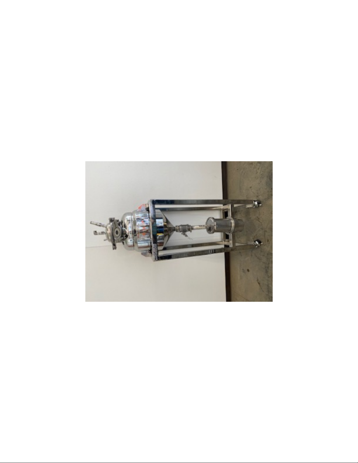
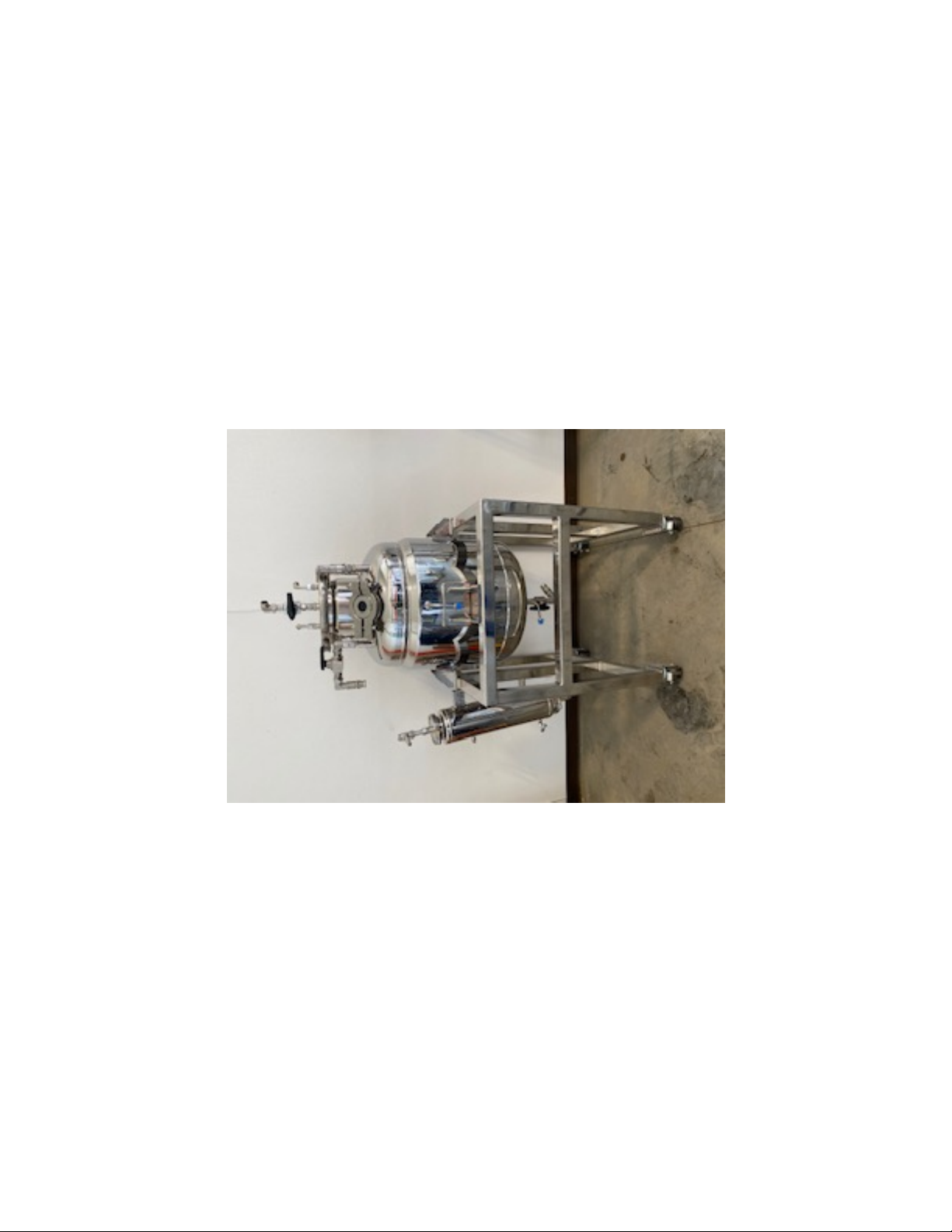
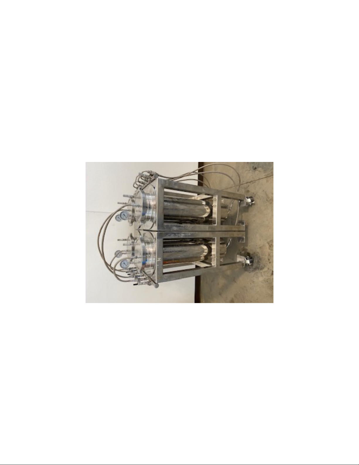
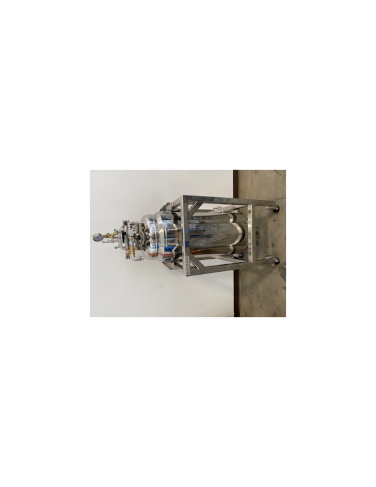
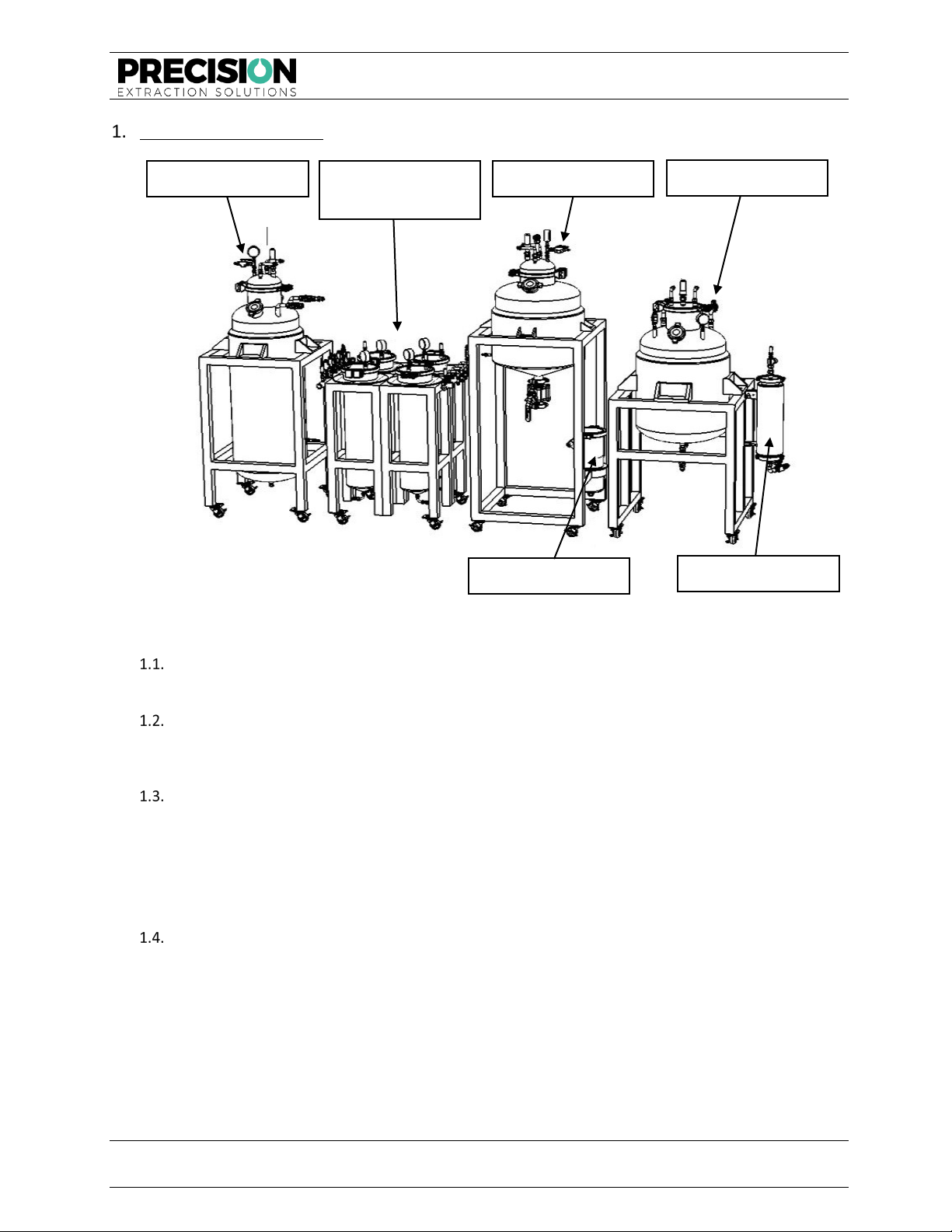
Section 1 - Components
Solvent Vessel
1.1.1. The Solvent Vessel contains the solvent, either LPG or ethanol, that dissolves the solute.
Material Columns
1.2.1. The solvent transfers from the Solvent Vessel into the Material Column and remains in the
Material Columns until reaching the desired soak time.
Dewax Column
1.3.1. The Dewaxing Column is used to separate the wax from the oil. The general steps are:
1.3.1.1. Solution is transferred into the Dewaxing Column from the Material Column.
1.3.1.2. Wax is precipitated from the soultion by chilling.
1.3.1.3. The dewaxed solution is transferred to the Collection Vessel.
Collection Vessel
1.4.1. The Collection Vessel receives the dewaxed solution. When using LPG as solvent, the solution is
boiled in the Collection Vessel, and solvent vapors are returned to the Solvent Vessel where
they are condensed back to a liquid. This recovered solvent can be used in the next extraction.
Expansion Vessel
Dewax Filter
Material
Columns
Solvent Vessel
Dewax Column
Collection Vessel

MODEL X40 MSE OPERATIONAL MANUAL
FOR HAZARDOUS ENVIRONMENTS
Model X40 MSE Operational Manual – For Hazardous Environments
Precision® Extraction Solutions Page 9 of 43
©2019 PX2 Holdings, LLC. All rights reserved. v04.29.2019
Section 2 - Getting Started
Review the following system installation and operation requirements information before preparing for
operation. Failure to do so may result in improper/unsafe installation and/or dangerous operating conditions.
System Placement
2.1.1. Place the system in a ventilated laboratory environment approved by the local fire marshal.
2.1.2. Place the system on a level surface.
Mounting of Components
2.2.1. Securely mount all vessels to the mounting rack.
2.2.2. Properly tighten mounting rack unions.
2.2.3. Level all components.
2.2.4. Lock all wheels on the mounting rack.
Chiller/Heater Options
2.3.1. For hazardous environments (Class I, Division 1 and Division 2 locations), both a liquid heat
source and cooling source will need to be plumbed into the hazardous area. Place the heater
and chiller in an area determined acceptable by the local building department.
2.3.2. UL listed equipment is typically required for this task. Submit a building plan to the local
municipality.
2.3.3. Speak to a Precision® Extraction Solutions technical representative to ensure the cooling and
heating options are adequate for seamless operation of the X40 MSE system in a passive
configuration. The X40 MSE extraction system comes pre-configured with heating and cooling
units suitable for this purpose.
Solvent Requirements
2.4.1. Use the X40 MSE extraction system with 100% ethanol, 100% butane, 100% propane, or any
blend of butane and propane.
2.4.2. Under no circumstances should ethanol and LPG be mixed in the X40 MSE. When changing
solvents, thoroughly clean the system.
MODEL X40 MSE OPERATIONAL MANUAL
FOR HAZARDOUS ENVIRONMENTS
Model X40 MSE Operational Manual – For Hazardous Environments
Precision® Extraction Solutions Page 10 of 43
©2019 PX2 Holdings, LLC. All rights reserved. v04.29.2019
Section 3 - Pressure Testing
The X40 MSE unit comes factory tested and inspected for sustained pressure holding capabilities. However,
shipping and moving of the unit may create pressure leaks and/or equipment exposure to drastic changes in
temperature. It is the operator's responsibility to check for pressure leaks prior to operation.
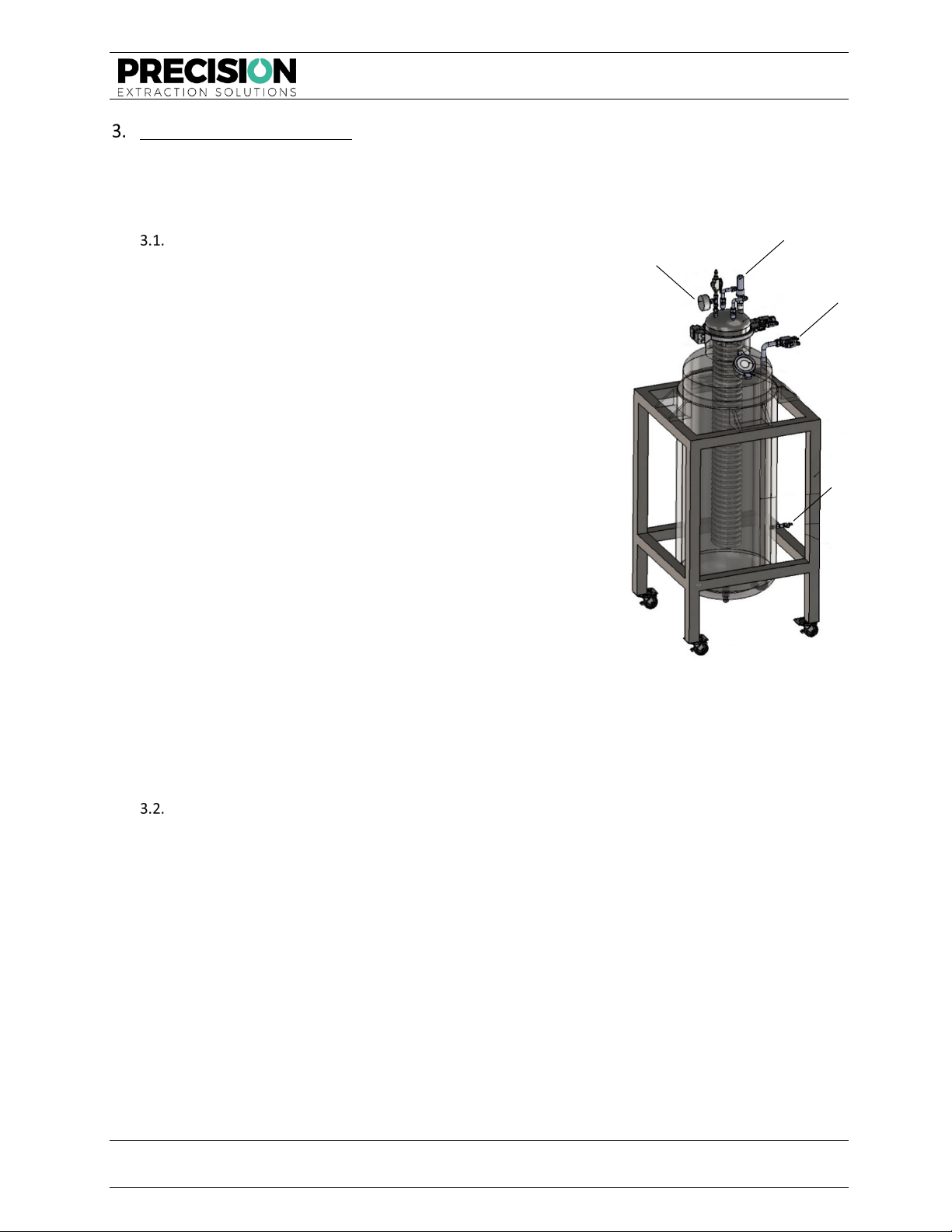
Checking the System for Leaks
3.1.1. Attach all the components and hose assemblies per
the drawing in this manual.
3.1.1.1. If pressure testing the entire new
system, include the Solvent Vessel.
3.1.1.2. If testing the system after filling the
Solvent Vessel, keep all valves on the
Solvent Vessel CLOSED. All remaining
valves should remain OPEN (excluding
valves leading to the atmosphere).
3.1.2. Attach a 1/4" MJIC hose to the Collection Vessel.
3.1.3. With all the valves open on the system (excluding
valves which leading to the atmosphere), bring the
system pressure to 150 psi, using compressed air via
an air compressor.
3.1.4. Open the vent down nipples on the gauge prior to
performing a pressure test.
3.1.5. Note the actual readings of the pressure gauge by
taking a photo for later comparison.
3.1.6. For a primary pressure test (first test), allow the
system to sit at 150 PSI for at least 24 hours. For a
secondary pressure test (any test performed after
the primary pressure test), allow the system to sit at 150 PSI for 1 hour.
3.1.7. Note any changes in pressure. Significant decreases in pressure indicate a leak, and the unit is
unsafe to operate.
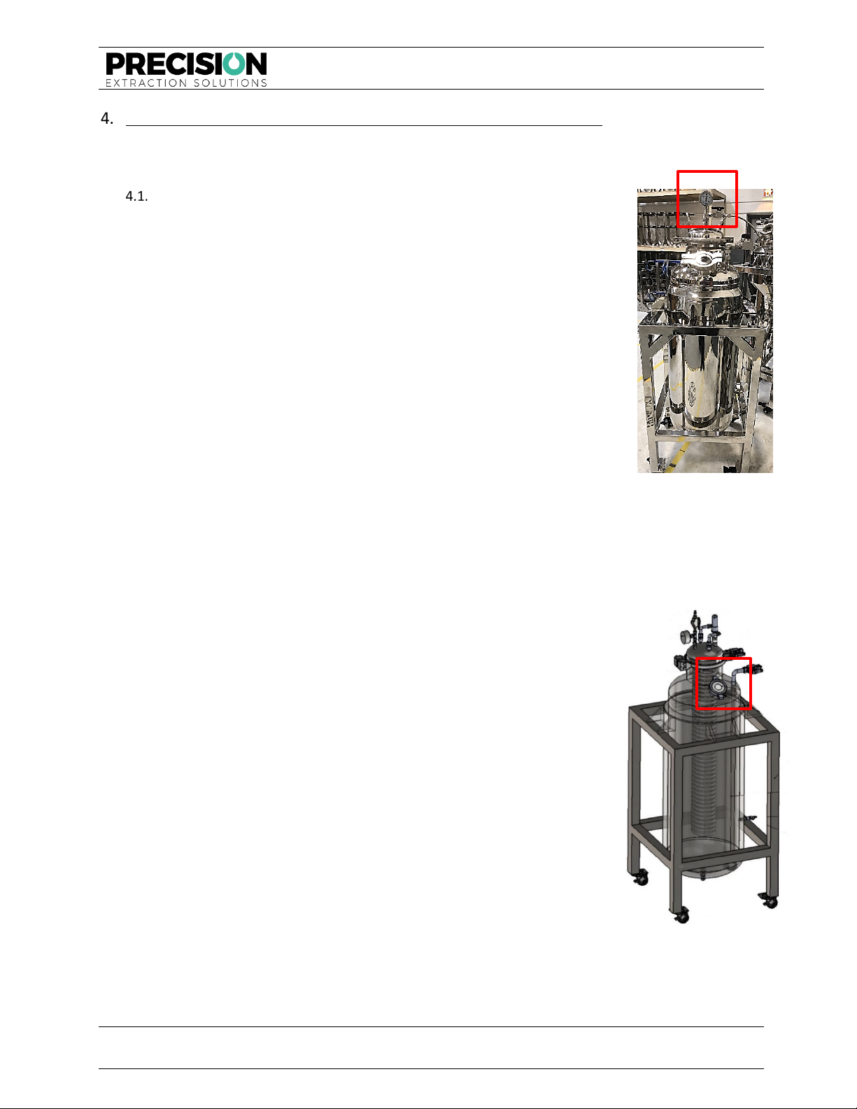
Identifying Leak Locations
3.2.1. Identify leaks by filling a spray bottle with soapy water and spraying the area of the unit where
the suspected leak is located. The presence of bubbles confirms a leak.
3.2.2. The most common areas for leaks are the valve seats (which could need to be re-taped) and the
sight glass (which may need to be re-tightened).
3.2.3. Before adjusting/tightening/re-taping any pieces on the unit, vent the system down to 0 psi.
3.2.4. Once the unit passes a pressure test, the Solvent Vessel is ready to be charged/filled.
Pressure Gauge
Vapor Valve
Siphon Valve
Vacuum Valve
Figure 1: Solvent Vessel Pressure Gauge
and Valves

MODEL X40 MSE OPERATIONAL MANUAL
FOR HAZARDOUS ENVIRONMENTS
Model X40 MSE Operational Manual – For Hazardous Environments
Precision® Extraction Solutions Page 11 of 43
©2019 PX2 Holdings, LLC. All rights reserved. v04.29.2019
Other Necessary Procedures and Notes
3.3.1. Inspect equipment cleanliness. Precision keeps equipment as clean as possible following
production; however, shipping and handling of the equipment
can cause contamination. It is the responsibility of the user to
ensure all surfaces are always clean and sanitary.
3.3.2. To clean the system perform a “wet run” with solvent, but
without material. Clean the Solvent Vessel with special
attention. Vacuum the Solvent Vessel with the hose by removing
the center tri-clamp fitting.
3.3.3. If using ONE chiller to cool MULTIPLE columns, use “T” joints to
split the feed and return lines to service both columns. Use TPE
hosing for these lines.
NOTE—It may be necessary to purchase extra lengths from a
hardware store to place the heater and chiller in the most
desirable spots for setup. Insulation on the lines AND the
columns is essential.
3.3.4. Once the heater and chiller are in place and the equipment is
free of leaks, the user must insulate all the chilled lines and
columns.
3.3.5. It is most desirable to use ½” quick release fittings for the
collection bowl. These fittings are available from Precision®
Extraction Solutions and make disconnecting the heat bath lines
much easier.
3.3.6. It is essential to insulate the lines and columns that connect to the
chiller. The better they are insulated, the more efficient the
machine and chiller will function.
3.3.7. It is highly recommended to purchase a stainless-steel insulated
hose kit from Precision® Extraction Solutions for the heaters and
chillers.
Figure 2: Solvent Vessel Clamp Fitting
Figure 3: Chiller
MODEL X40 MSE OPERATIONAL MANUAL
FOR HAZARDOUS ENVIRONMENTS
Model X40 MSE Operational Manual – For Hazardous Environments
Precision® Extraction Solutions Page 12 of 43
©2019 PX2 Holdings, LLC. All rights reserved. v04.29.2019
Section 4 - Charging/Filling Solvent Vessel with Hydrocarbon Solvent
Use the following procedure for charging/filling the Solvent Vessel. Common issues and solutions are included
after the procedure description. Always disconnect the vacuum pump prior to introducing solvent.
Procedure for Charging/Filling the Solvent Vessel
4.1.1. Wheel the solvent tank onto the scale.
4.1.2. Fill the Solvent Vessel with no more than 120 LBS of hydrocarbon or
100L of ethanol for the X40 MSE model. It should appear through the
sight glass to be about 75–80% full.
4.1.3. Attach the solvent source to the X40 MSE Solvent Vessel via a 1/4" FJIC
Line.
4.1.4. Verify the fittings are correct to safely attach the source vessel to the
X40 MSE Solvent Vessel. These fittings vary by supplier. Check with the
hydrocarbon solvent supplier to procure the proper fittings.
4.1.5. To charge the X40 MSE Solvent Vessel, begin by vacuuming the vessel
down to -30 inHg or until the vacuum pump bottoms out. Ensure the
line from the X40 MSE Solvent Vessel to the solvent source vessel is
under a vacuum.
4.1.6. Cool the Solvent Vessel.
NOTE—If using a Precision chiller, turn on the chiller and allow the vessel
to cool. Depending on atmospheric conditions, the solvent source vessel
may need warming. This can be done by placing the vessel in a hot water bath.
4.1.7. Fill the X40 MSE Solvent Vessel with it detached from the mounting rack, while sitting on a
refrigerant scale.
4.1.8. Start with all valves closed, then open the valve on the X40 MSE
Solvent Vessel leading to the solvent source.
4.1.8.1. Open the valve on the solvent source vessel.
4.1.8.2. Note the flow rate into the X40 MSE Solvent Vessel.
4.1.8.3. For the initial fill of the system, use a refrigerant scale.
Figure 5: Solvent Vessel Sight Glass
Figure 4: Solvent Vessel Pressure
Gauge
MODEL X40 MSE OPERATIONAL MANUAL
FOR HAZARDOUS ENVIRONMENTS
Model X40 MSE Operational Manual – For Hazardous Environments
Precision® Extraction Solutions Page 13 of 43
©2019 PX2 Holdings, LLC. All rights reserved. v04.29.2019
Section 5 - Preparing for Operation
Prior to use, the operator must read and be familiar with the specific operation manual of the recovery
equipment (e.g., pump/compressor operational manuals). The following procedure outlines the steps for
preparing for passive and active operation. Tighten all connections with an adjustable wrench before
proceeding.
NOTE—For active recovery using either a Precision GC 5000 pump or other recovery equipment, adhere to the
following procedure.
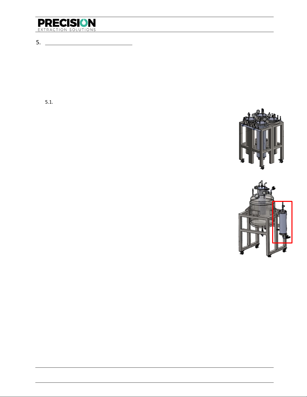
Initial Preparation
5.1.1. Verify the Material Column matches the weight and volume of the
material to be processed.
5.1.2. Ensure the Material Column mounts properly to the mounting rack.
5.1.3. Fill the Material Column with the material to be processed. Leave about 1-
2 inches of headspace at the top of the column. The packing density of the
material is at the operator's discretion.
5.1.4. Attach the Material Column cap to the top of column.
NOTE—For new users to a closed loop system, the manufacturer
recommends the operator bypass the Dewaxing Column until more
familiar with the X40 system.
5.1.5. At the operator's discretion, fill the Expansion Column with a blend of 3A
and 4A molecular sieves. Molecular seives can be purchased from Delta
Adsorbents. Precision recommends changing dessicant every 10 runs. The
lifespan of dessicant is dependant on the moisture content of the material
being extracted
5.1.6. Begin operating the recirculating chiller.
5.1.7. Cool the Solvent Vessel to the desired temperature via the chiller.
NOTE—Cooling the Solvent Vessel reduces the vapor pressure of the
solvent. This will reduce the amount of solvent that can be passively
transferred into the material column.
5.1.8. If using the Dewaxing Column, cool it via the chiller. It takes approximately
45– 60 minutes for the Dewaxing Column to reach the acceptable
temperature range (-30° C) – (-50° C).
5.1.9. The chiller should be operating at the desired solvent temperature continuously. This minimizes
system downtime and allows for the storage of solvent in the Solvent Vessel overnight.
Figure 6: Material Column
Figure 7: Expansion Column

MODEL X40 MSE OPERATIONAL MANUAL
FOR HAZARDOUS ENVIRONMENTS
Model X40 MSE Operational Manual – For Hazardous Environments
Precision® Extraction Solutions Page 14 of 43
©2019 PX2 Holdings, LLC. All rights reserved. v04.29.2019
5.1.10. As the Solvent Vessel and Dewaxing Column cool, vacuum all remaining
columns and hoses. Attach the vacuum pump to the Collection Vessel and
open the proper valves. Vacuum the system until the pump "bottoms
out" or until reaching approximately -30 inHg.
5.1.11. To comply with Class 1, Division 1 or Class 1, Division 2 standards,
applications in hazardous environments can route the vacuum line outside
the classified room.
5.1.12. With the Solvent Vessel and Dewaxing Column chilled and the system
under a full vacuum, the system is now ready to run.
Preparing for PASSIVE Operation
5.2.1. Connect a hose from the ball valve at the bottom of the Expansion Column
to the inlet side of the condenser coil. The inlet side of the coil leads
to the bottom of the condenser coil first. The return hose is a ¾”
MJIC fitting on one end and a ¾” compression fitting on the other
end.
5.2.2. Connect a hose from the outlet side of the condenser coil to the
return valve on the Solvent Vessel. The return valve is located on the
collar of the Solvent Vessel in the left, rear position. This section of
the return line will be a MJIC fitting on both ends.
Preparing for ACTIVE Operation
5.3.1. Connect the active recovery pump to the closed loop system:
5.3.1.1. Connect the hose from the outlet valve on the Expansion
Column to the inlet side of the active recovery pump. In
most cases, this hose is a ¾” compression fitting on one
end and a ¾” MJIC fitting on the other end.
5.3.1.2. Connect the hose from the outlet of the active recovery pump to the inlet on the
condenser coil. The inlet of the condenser coil is the line that goes to the bottom of
the coil.
5.3.1.3. Connect a hose from the outlet on the condenser coil to the return valve on the
Solvent Vessel. The return valve is located on the collar of the solvent in the rear,
left position.
5.3.2. Turn on the heater attached to the Collection Vessel and Expansion Column.
Figure 8: Recirculating Chiller
Figure 9: Expansion Column
Ball Valve

MODEL X40 MSE OPERATIONAL MANUAL
FOR HAZARDOUS ENVIRONMENTS
Model X40 MSE Operational Manual – For Hazardous Environments
Precision® Extraction Solutions Page 15 of 43
©2019 PX2 Holdings, LLC. All rights reserved. v04.29.2019
Section 6 - Running the Extractor (Hydrocarbon)
The procedure for connecting the X40 system to a GC
5000 Recovery Pump for active recovery is provided in
Section 2 of this manual. The operator of such
equipment must read and be familiar with the specific
operational manual of the recovery equipment prior to
use (e.g., pump/compressor operation manuals).
If the user is new to using a closed loop system,
Precision recommends that the user bypass the
Dewaxing Column until the user becomes more familiar
with the X40 system. Dewaxing is not always necessary
and may be counterproductive to the user’s specific
desired product types.
Keep the Solvent Vessel as cold as possible during the
recovery process. This helps condense the solvent as it returns to the Solvent Vessel.
Use the following procedure to begin operating the extractor using hydrocarbon
solvents.
Pressurize Solvent Vessel
6.1.1. All ball valves on the system should now be in the CLOSED position.
6.1.2. Attach hose from nitrogen regulator to the ¼” MJIC vapor valve on the
Solvent Vessel.
6.1.3. Set the regulator to 30 psi above the desired pressure.
6.1.4. Open the vapor valve on the Solvent Vessel.
6.1.5. Allow pressure to reach desired level.
6.1.6. Close vapor valve.
Transfer Solvent to Material Columns
6.2.1. Open the siphon tube valve on the Solvent Vessel - this valve leads to the
manifold on the left side of the Material Column stand.
6.2.2. Open the large ball valve on the solvent manifold - this manifold is located along the left side of
the Material Column stand.
6.2.3. Fill Material Column 1 by opening valve 1 on the manifold. Solvent
begins to flow into the Material Column. Allow solvent to flood the
Material Column. The Material Column is full when the pressure in the
column is within a few psi of the Solvent Vessel pressure.
6.2.4. Close valve 1 on the solvent manifold.
6.2.5. If necessary, re-pressurize the Solvent Vessel headspace with nitrogen to
fill the second column—refer to 6.1.
6.2.6. Fill Material Column 2 by opening valve 2 on the manifold. Solvent
begins to flow into the Material Column. Allow solvent to flood the
Material Column. The Material Column is full when the pressure in the
column is within a few psi of the Solvent Vessel pressure.
6.2.7. Close valve 2 on the solvent manifold.
Figure 10: Dewaxing Column
Figure 11: Solvent Vessel
Vapor Valve
Figure 12: Material
Column Outlet Manifold
Table of contents
Other Precision Industrial Equipment manuals


Popular Industrial Equipment manuals by other brands


Enerpac
Enerpac ECH-52 instruction sheet

PCB Piezotronics
PCB Piezotronics M352C66 Installation and operating manual

Dover
Dover Marathon V-4224 Operation, maintenance and installation manual

Polar Instruments
Polar Instruments GRS550 user guide

Endress+Hauser
Endress+Hauser Prothermo NMT 539 Operating instruction

Uniflex
Uniflex UA 4 Operation manual