Precor P80 Console User manual

© Precor Incorporated, Unauthorized Reproduction and Distribution Prohibited by Law Page 1
P80 CONSOLE
20039-179 REV A01
PRECOR CUSTOMER SUPPORT
Service Manual


© Precor Incorporated, Unauthorized Reproduction and Distribution Prohibited by Law Page 1
Contents
Section 1 - Introduction ........................................................................................... 5
About this Document ........................................................................................................................................................5
Safety Guidelines ................................................................................................................................................................5
Section 2 - Verifying Proper Installation ............................................................ 7
Equipment Base Cabling ...................................................................................................................................................7
P80 Power Requirements.................................................................................................................................................7
Treadmill Specific Concerns............................................................................................................................................7
Cable Routing Through the P80 Armor .......................................................................................................................9
1-Stop Switch Cable Routing.............................................................................................10
2-RF Coax Cable Routing...................................................................................................11
3-Ethernet Cable Routing...................................................................................................13
4-Data Cable Routing.........................................................................................................14
5-Auto-Stop Cable Routing................................................................................................15
6-Power Cable Routing.......................................................................................................16
7-Heart Rate Cable Routing...............................................................................................17
Mounting the P80 Console............................................................................................................................................18
Initial Configuration Steps.............................................................................................................................................20
Steps to Perform on Each And Every P80 ................................................................................................................20
Steps that can be Cloned (copied) .............................................................................................................................20
Section 3 - Operation Verification ......................................................................21
Procedure............................................................................................................................................................................ 21
Operation Verification Checklist................................................................................................................................. 23
Section 4 - Accessing the Service Software Menus......................................25
Settings Menu................................................................................................................................................................... 25
About Menu ...................................................................................................................................................................... 29
Equipment Usage Menu ................................................................................................................................................ 32
System Settings Menu ................................................................................................................................................... 34
Section 5 - System Tests and Workout Limits ...............................................37
System Tests..................................................................................................................................................................... 37
P80 Workout Limits........................................................................................................................................................42
Section 6 - Updating Software........................................................................... 45
Acquiring P80 Software from the Precor FTP Site.................................................................................................46
Installing P80 software into the P80 console..........................................................................................................49
Procedure..............................................................................................................................49
Section 7 - Display and Entertainment Settings ............................................55
P80 Display ....................................................................................................................................................................... 55
P80 TV Settings ............................................................................................................................................................... 59
Channel Guide .................................................................................................................................................................. 62
To scan for available channels:........................................................................................62

© Precor Incorporated, Unauthorized Reproduction and Distribution Prohibited by Law Page 2
To name a channel:............................................................................................................62
To delete a channel from the Channel Guide:.............................................................66
How to update the channel plan:....................................................................................66
Section 8 - Cloning Settings................................................................................ 69
P80 Manage Settings (Cloning)..................................................................................................................................69
P80 Manage Settings Table................................................................................................69
P80 Cloning Procedure ................................................................................................................................................... 71
Section 9 - Connectivity and Registration.......................................................77
P80 Connectivity ............................................................................................................................................................. 77
To view connectivity information:.....................................................................................77
P80 Connectivity Set Up and Registration Procedure ..................................................79
Troubleshooting Procedures................................................................................83
Verifying the Hardware Version.................................................................................................................................. 83
Boot Error resulting in Yellow Triangle Being Displayed...................................................................................... 85
Possible Causes.....................................................................................................................85
Possible Remedies................................................................................................................85
Boot Error resulting in Red Triangle Being Displayed............................................................................................86
Description.............................................................................................................................86
Possible Causes.....................................................................................................................86
Possible Remedies................................................................................................................86
Preva Net Panel Icon Not Displayed .......................................................................................................................... 87
Description.............................................................................................................................87
Possible Causes.....................................................................................................................87
Possible Remedies................................................................................................................87
Preva Net Panel Displayed but Web Pages and/or RSS Feeds Do Not Load ................................................. 88
Description.............................................................................................................................88
Possible Causes.....................................................................................................................88
Possible Remedies................................................................................................................88
Sign-in Button Does Not Appear On the Welcome Screen.................................................................................89
Description.............................................................................................................................89
Possible Causes.....................................................................................................................89
Possible Remedies................................................................................................................89
Black Screen - Full Console ...........................................................................................................................................90
Description.............................................................................................................................90
Possible Causes.....................................................................................................................90
Possible Remedies................................................................................................................90
Boot Screen Procedure.......................................................................................................90
Poor Quality Video - Single Unit Only ........................................................................................................................91
Description.............................................................................................................................91
Possible Causes.....................................................................................................................91
Possible Remedies................................................................................................................91
Poor Quality Video – All Units ..................................................................................................................................... 92
Possible Causes.....................................................................................................................92
Possible Remedies................................................................................................................92

© Precor Incorporated, Unauthorized Reproduction and Distribution Prohibited by Law Page 3
Poor Quality Video – One Channel(s) or Limited Channels................................................................................ 93
Description.............................................................................................................................93
Possible Causes.....................................................................................................................93
Possible Remedies................................................................................................................93
Green Screen.....................................................................................................................................................................94
Description.............................................................................................................................94
Possible Causes.....................................................................................................................94
Possible Remedies................................................................................................................94
Stuttering Channels......................................................................................................................................................... 95
Description.............................................................................................................................95
Possible Causes.....................................................................................................................95
Possible Remedies................................................................................................................95
Touch Screen Slow Response ......................................................................................................................................96
Description.............................................................................................................................96
Possible Causes.....................................................................................................................96
Possible Remedies................................................................................................................96
Touch Screen Responds Incorrectly to Touch or is Unresponsive .................................................................... 97
Description.............................................................................................................................97
Possible Causes.....................................................................................................................97
Possible Remedies................................................................................................................97
Screen Calibration Procedure...........................................................................................97
Poor Quality Video - One Channel or Limited Channels......................................................................................98
Possible Causes.....................................................................................................................98
Possible Remedies................................................................................................................98
Poor Audio Quality – All Channels, Multiple Units................................................................................................99
Description.............................................................................................................................99
Possible Causes.....................................................................................................................99
Possible Remedies................................................................................................................99
Machine Controls Unresponsive...............................................................................................................................100
Description...........................................................................................................................100
Possible Causes...................................................................................................................100
Possible Remedies..............................................................................................................100
Message Out of Service Displayed............................................................................................................................ 101
Description...........................................................................................................................101
Possible Causes...................................................................................................................101
Possible Remedies..............................................................................................................101
Message Please Reset the Treadmill Displayed ................................................................................................... 102
Description...........................................................................................................................102
Possible Causes...................................................................................................................102
Possible Remedies..............................................................................................................102
Unit reboots of its own volition.................................................................................................................................. 103
Description...........................................................................................................................103
Possible Causes...................................................................................................................103
Possible Remedies..............................................................................................................103
Treadmill - Resets to Welcome Screen at Beginning of the “3…2…1…” Countdown.................................. 104
Description...........................................................................................................................104

Possible Remedies..............................................................................................................104


© Precor Incorporated, Unauthorized Reproduction and Distribution Prohibited by Law Page 4
USB Flash Drive Not Recognized............................................................................................................................... 105
Description...........................................................................................................................105
Possible Causes...................................................................................................................105
Possible Remedies..............................................................................................................105
Section 11 - Replacement Procedures..............................................................107
Upper Component Access: ......................................................................................................................................... 107
The Main Vented Access Cover & Components.................................................................................................. 108
Replacing the P80 Console ......................................................................................................................................... 109
Console Mounting - Removal..........................................................................................109
Disconnecting Cables.......................................................................................................110
Console Installation............................................................................................................112
Cable Connections...........................................................................................................113
Securing the P80 Console.................................................................................................116
Replacing the P80 Heart Rate PCA Board....................................................................116
Procedure............................................................................................................................116
Section 12 - Wiring & Block Diagrams.............................................................. 119
Section 13 - Replaceable Parts Identification ............................................... 123

© Precor Incorporated, Unauthorized Reproduction and Distribution Prohibited by Law Page 5
About this Document
Warning: This service manual is for use by Precor trained service providers only. If you are not a Precor
Trained Servicer, do not attempt to service any Precor products. Call your dealer for service.
This document contains information required to perform the majority of troubleshooting and replacement
procedures required to repair and maintain this product.
This document contains general product information, software diagnostic procedures (when available),
preventative maintenance procedures, inspection and adjustment procedures, troubleshooting
procedures, replacement procedures and electrical block and wiring diagrams.
Safety Guidelines
Additional safety guidelines are included in the owner’s manual.
Operate the equipment on a solid, level surface. Visually check the equipment before beginning service or
maintenance operations. If it is not completely assembled or is damaged in anyway, do not attempt to
operate the equipment.
To prevent electrical shock, keep all electrical components away from water and other liquids.
Do not use accessory attachments that are not recommended by the manufacturer-such attachments
might cause injuries.
Section 1 - Introduction
Section


© Precor Incorporated, Unauthorized Reproduction and Distribution Prohibited by Law Page 7
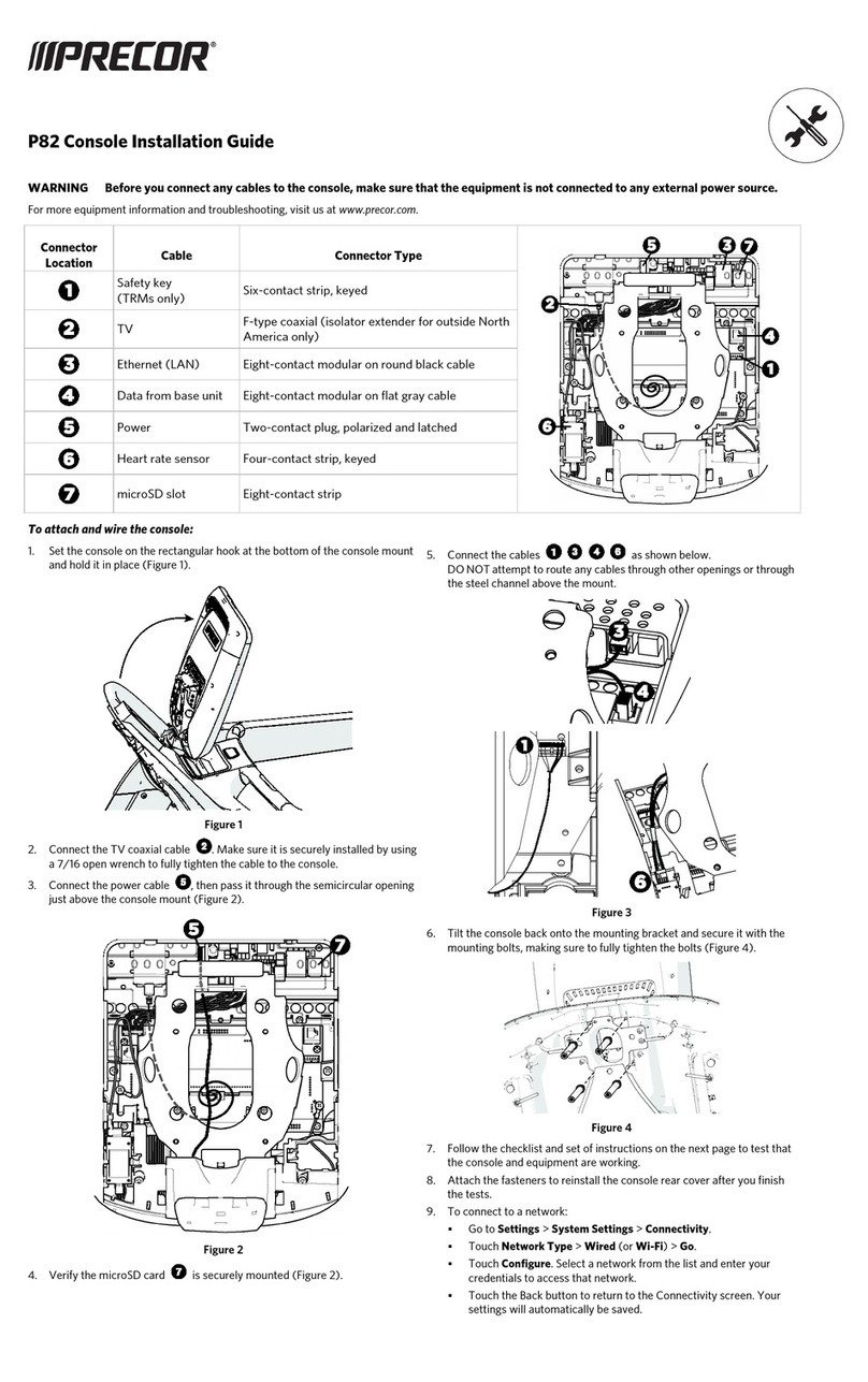
Cables connecting the P80 should be routed in a very specific order and in a very specific path to avoid
damage to the cables. This section is a systematic process on how the cables should be routed through
the P80 console. Functionality issues could occur if the cables have been routed in a manner other than
described in this section. If you have a functionality problem with a P80 console, verifying that these
cables were routed correctly prior to any other troubleshooting could save you time and frustration.
Equipment Base Cabling
For cable routing through the specific equipment base, refer to the installation guide shipped with the
specific equipment base type (TRM, EFX, AMT, RBK, and UBK).
P80 Power Requirements
To operate the P80 requires a separate 12Vdc power supply. The 12Vdc power supply will be mounted to
the inside of the frame of the treadmill using Velcro strips.
For ALL other units (because they are self powered) the 12Vdc power supply must be outside of the
equipment covers, typically in a cable management "Tee" connector or other customer supplied cable
management. Except for the TRM, make sure the power supply cable’s ground lug is grounded to the
equipment frame.
Treadmill Specific Concerns
The cables entering the display support column should be routed from the side above the stop switch
assembly, not through the hole at the bottom of the display support column. The cables should then be
arranged in the clips in the display support column as shown below.
The ends of the cables should be routed through the display support column, behind the console mounting
plate, and out through the hole in the center of the weldment. There should be a total of 7 cables (8
cables if you consider that the heart rate cable is physically 2 cables going into one connector) exiting the
center hole in the console mounting plate.
Cables not routed in this manner can be pinched and/or damaged during installation.
Section 2 - Verifying
Proper Installation

© Precor Incorporated, Unauthorized Reproduction and Distribution Prohibited by Law Page 8
Figure 1: TRM Console Support & Cable Routing

© Precor Incorporated, Unauthorized Reproduction and Distribution Prohibited by Law Page 9
Cable Routing Through the P80 Armor
In the back of the P80 console is a large black steel support, called the Armor. At the bottom of the unit’s
mounting plate there is a hook that holds the console in place, leaving your hands free to perform the
cable routing steps. Remove the 4 console mounting screws and tilt the console forward, allowing the
hook to support the console. Verify the cable routing against the following steps. Cables should be routed
through the center of the armor and out specific side openings in the armor. The specific order and path
that these cables are routed allow them to be attached to their respective connectors without being
pinched and/or damaged.
Cable Routing Order
1 Stop Switch Cable
2 RF Coax Cable
3 Ethernet Cable
4 Data Cable
5 Auto-Stop Cable
6 Power Cable
7 Heart Rate Cable
Figure 2: Console on Mounting Hook

© Precor Incorporated, Unauthorized Reproduction and Distribution Prohibited by Law Page 10
1-Stop Switch Cable Routing
The Stop Switch assembly cable (treadmill only) should be routed through the lower right corner of the
armor, and connected to the 6 pin flat connector on the CPA board. The cable will go through the center
of the armor, out the bottom right side opening, then up to the connector. Be sure to get the connector
onto the six pins correctly or the treadmill will not work.
Figure 3: Stop Cable Routing (Treadmill Only)

© Precor Incorporated, Unauthorized Reproduction and Distribution Prohibited by Law Page 11
2-RF Coax Cable Routing
a) The RF Coax cable should be routed down below the tuner, and out the right bottom side of the
armor. This is easier if you straighten the cable and gently push it through the center of the armor,
in the direction as shown. Use your finger to guide the cable out the bottom right side opening and
feed about 10 inches through.
Figure 4: Coax Cable Starting Path
b) The RF Coax cable should reach up and over the top of the armor connecting it to the flexible cable
attached to the tuner.
When connecting to the flexible cable, take care to not damage the cable. Being
flexible, it is also fragile and can become damaged if handled roughly.

© Precor Incorporated, Unauthorized Reproduction and Distribution Prohibited by Law Page 12
Figure 5: Coax Cable Ending Path
c) The RF Coax connector should be secured in place with the zip tie provided with the console. It is
important that the connection be tied to the frame in this location to prevent the cable being
pinched and possibly causing rattling noises during use. If the zip tie is missing, locate one and
secure the connection. Be sure to get the zip tie on the connector and not on the cable.
Figure 6: Coax Connector Zip Tie

© Precor Incorporated, Unauthorized Reproduction and Distribution Prohibited by Law Page 13
3-Ethernet Cable Routing
The Ethernet cable should be routed through the center of the armor, and then through the opening in the
upper right side of the armor. The Ethernet cable connects to the upper RJ45 type connector. The
Ethernet cable will always be black and round.
Figure 7: Ethernet Cable Routing

© Precor Incorporated, Unauthorized Reproduction and Distribution Prohibited by Law Page 14
4-Data Cable Routing
The Data cable should be routed through the center of the armor, and then through the opening in the
upper right side of the armor. The Data cable attaches to the lower RJ45 type connector. The data cable
will always be grey and flat.
Figure 8: Data Cable Routing

© Precor Incorporated, Unauthorized Reproduction and Distribution Prohibited by Law Page 15
5-Auto-Stop Cable Routing
The Auto Stop cable (treadmill only) should be routed through the center of the armor, and then through
the upper left corner of the weldment. The connector will be a four pin keyed connector.
Figure 9: Auto Stop Cable Routing

© Precor Incorporated, Unauthorized Reproduction and Distribution Prohibited by Law Page 16
6-Power Cable Routing
The Power cable should be routed through the center of the armor, and then through the upper left corner
of the weldment. If the P80 is hardware version 1, It is possible that when you are dressing the cables to
pull this connector back inside the weldment. Leave the connector on the side of the P80 as shown, as it
might be necessary to access it for troubleshooting. Version 1.5 hardware will connect to the power supply
board.
Figure 10: 1_5 Power Cable Routing (Prior to version 1.5 Hardware)
Figure 11: Power Cable (Version 1.5 Hardware or Later)

© Precor Incorporated, Unauthorized Reproduction and Distribution Prohibited by Law Page 17
7-Heart Rate Cable Routing
The Heart Rate cable should be routed through the center of the armor, and then through the upper left
corner of the weldment. Route any excess Heart Rate cable into the rectangular center section of the dash
assembly.
Figure 12: Heart Rate Cable Routing

© Precor Incorporated, Unauthorized Reproduction and Distribution Prohibited by Law Page 18
Mounting the P80 Console
1 Double check that all cables are fully and securely connected, and that cables are tied back properly.
Make sure any extra cabling is pulled down through the neck.
NOTE:
***For treadmill installations, make sure that the cables from the upright to the
mounting neck are routed along the front of the dash (using the attached flex ties),
making sure the cables are routed through the plastic guides inside the neck. ***
Figure 13: Dash Cable Routing
2 Tilt the control console back onto the mounting plate until the tab on the top edge of the armor slides
along the top edge of the mounting plate and the screw holes align properly.
3 Secure the console to the plate using the four flat head 5/8 inch long screws in the hardware kit. Use
the 5/8 inch long screws that come in the hardware kit, as they are a custom length for this location. If
you need additional screws (part number MCCN025-031) contact Precor. ½ inch screws are too short
to provide the proper grounding required by the P80 and ¾ inch are too long and can damage wires.
Other manuals for P80 Console
7
Table of contents
Other Precor Fitness Electronic manuals

Precor
Precor 100i User manual

Precor
Precor Console User manual

Precor
Precor Spinner Chrono Manual

Precor
Precor PVS User manual

Precor
Precor P30 Console Manual

Precor
Precor P80 Console Assembly Instructions

Precor
Precor P10 Assembly Instructions

Precor
Precor P30 Console Assembly Instructions

Precor
Precor Spinner Chrono User manual

Precor
Precor P30 Console User manual