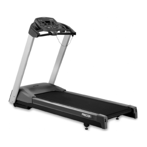
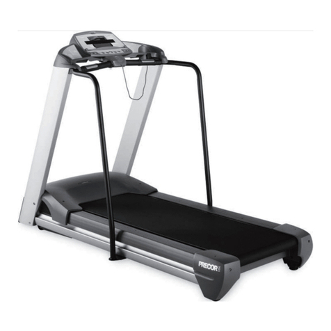
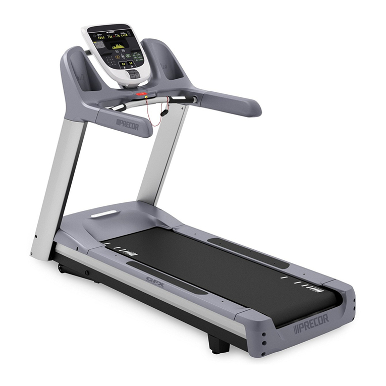
Precor TRM10/GEN06 User manual

© Precor Incorporated, Unauthorized Reproduction and Distribution Prohibited by Law Page 1
TRM10/ GEN06 TREADMILL BASE
20039-165 REV A04
PRECOR CUSTOMER SUPPORT
Service Manual


© Precor Incorporated, Unauthorized Reproduction and Distribution Prohibited by Law Page 1
Contents
Section 1 - About This Document ........................................................................................... 5
Section 2 - General Information ............................................................................................. 6
GEN-06/ TRM10 Treadmill Base ......................................... 6
Lubricants ........................................................... 6
Electrical Requirements .............................................. 6
Section 3 - Safety Guidelines ................................................................................................... 8
Section 4 - Operation Verification.......................................................................................... 9
Operation Verification ............................................... 9
Procedure ................................................................................................................................ 9
Operation Verification Checklist .................................... 11
Section 5 - Standardized Service Access Codes................................................................... 12
Service Access Codes ................................................ 12
Accessing the Service Software ...................................... 12
P80 Console........................................................................................................................... 13
Access Code Table ................................................... 14
P20 Console Service Software Access ................................. 15
Hardware Validation - Diagnostic Tests (51765761) ................... 16
Club Parameter - Settings (5651565) ................................. 17
Information Display (65) ............................................ 18
Section 6 - Theory Of Operation........................................................................................... 19
Consoles ............................................................ 19
Basic operation of a console............................................................................................. 19
Consoles that could appear on the GEN-06 / TRM10 Treadmill Base........................ 20
Console To Base Communication ....................................... 22
Treadmill Base Operation ............................................ 23
Power Entry............................................................................................................................ 23
Lower Electronics Module .................................................................................................. 24
AC Drive Motor Controller .................................................................................................. 25
Auto-Stop............................................................................................................................... 27
AC Lift System –Motion Control ........................................................................................ 28
AC Lift System –Position Monitoring ................................................................................. 30
Section 7 - TRM Base Troubleshooting Procedures ........................................................... 31
Introduction to Treadmill Troubleshooting ........................... 31
Troubleshooting Tripped Breakers .................................... 31
If the unit trips the wall breaker: ........................................................................................ 32
If the Treadmill breaker (power switch) is tripped:......................................................... 33
Troubleshooting No Power to the Console ............................. 35
Standardized Error Codes ............................................ 36
Error Codes ............................................................................................................................ 38
Error Code Table................................................................................................................... 39
Validating the Reported Failure ........................................................................................ 40

© Precor Incorporated, Unauthorized Reproduction and Distribution Prohibited by Law Page 2
Troubleshooting Input Power & Control Error Codes ................... 41
Error 05 - Key Depressed at Power Up.............................................................................. 41
Description............................................................................................................................. 41
Possible Causes..................................................................................................................... 41
Possible Remedies ................................................................................................................ 41
Error 09 - Lower PCA Memory Test Errors .......................................................................... 42
Description............................................................................................................................. 42
Possible Cause ...................................................................................................................... 42
Possible Remedy................................................................................................................... 42
Error 12 - Watchdog (Lower PCA)..................................................................................... 43
Description............................................................................................................................. 43
Possible Causes..................................................................................................................... 43
Possible Remedies ................................................................................................................ 43
Error 15 - A.C. Input Voltage Too High.............................................................................. 44
Description............................................................................................................................. 44
Possible Causes..................................................................................................................... 44
Possible Remedies ................................................................................................................ 44
Error 16 - A.C. Input Voltage Too Low .............................................................................. 46
Description............................................................................................................................. 46
Possible Causes..................................................................................................................... 46
Possible Remedies ................................................................................................................ 46
Error 80, 81, 82, & 83 –P30 Machine Controls Not Working.......................................... 47
Description............................................................................................................................. 47
Possible Causes..................................................................................................................... 47
Possible Remedies ................................................................................................................ 47
Troubleshooting the 3 Phase AC Drive Motor System ................... 48
Procedure:............................................................................................................................. 48
Error 20 - Too many Maximum Power Requests in 1 Second ....................................... 51
Description............................................................................................................................. 51
Possible Causes..................................................................................................................... 51
Possible Remedies ................................................................................................................ 51
Error 27 - Too Much Drive Motor Current ......................................................................... 52
Description............................................................................................................................. 52
Possible Causes..................................................................................................................... 52
Possible Remedies ................................................................................................................ 52
Error 28 - Temperature Too High ........................................................................................ 53
Description............................................................................................................................. 53
Possible Causes..................................................................................................................... 53
Possible Remedies ................................................................................................................ 53
Error 29 - Excessive AC Input Current................................................................................ 54
Description............................................................................................................................. 54
Possible Causes..................................................................................................................... 54
Possible Remedies ................................................................................................................ 54
Troubleshooting the Incline System .................................. 55
Operation of lift motor for testing: .................................................................................... 55
Error 40 - No Lift Motion Detected..................................................................................... 56
Description............................................................................................................................. 56
Possible Causes..................................................................................................................... 56
Possible Remedies ................................................................................................................ 56

© Precor Incorporated, Unauthorized Reproduction and Distribution Prohibited by Law Page 3
Error 42 - Lift Position Value Out of Range ....................................................................... 61
Troubleshooting Procedure ................................................................................................ 61
Description............................................................................................................................. 61
Possible Cause ...................................................................................................................... 61
Possible Remedies ................................................................................................................ 61
Error 44 - Un-commanded Lift Motion .............................................................................. 64
Description............................................................................................................................. 64
Possible Causes..................................................................................................................... 64
Possible Remedies ................................................................................................................ 64
Error 45 - Lift Moving in Wrong Direction .......................................................................... 65
Description............................................................................................................................. 65
Possible Causes..................................................................................................................... 65
Possible Remedies ................................................................................................................ 65
Troubleshooting Communications Errors ............................... 66
Error 30, 31, 32 and 33 - Communications Error .............................................................. 66
Description............................................................................................................................. 66
Possible Causes..................................................................................................................... 66
Possible Remedies ................................................................................................................ 66
Error 37 - E-Stop Not Communicating............................................................................... 67
Description:............................................................................................................................ 67
Possible Cause: ..................................................................................................................... 67
Possible Remedies:............................................................................................................... 67
Running Belt & Deck Troubleshooting ................................. 68
Procedure .............................................................................................................................. 68
Troubleshooting the Auto Stop Feature ............................... 70
Error 60 or “Temporarily Out of Order” – Auto Stop Not Working................................ 73
Description............................................................................................................................. 73
Possible Causes..................................................................................................................... 73
Possible Remedies ................................................................................................................ 73
Error 61 or “Temporarily Out of Order” – Auto Stop Not Present ................................. 75
Description............................................................................................................................. 75
Possible Causes..................................................................................................................... 75
Possible Remedies ................................................................................................................ 75
Troubleshooting Heart Rate Issues .................................................................................... 77
Hand Held Heart Rate Does Not Work............................................................................. 77
Wireless Heart Rate Does Not Work .................................................................................. 78
Possible sources of interference signals include, BUT NOT LIMITED TO:...................... 78

© Precor Incorporated, Unauthorized Reproduction and Distribution Prohibited by Law Page 4
Section 8 - Replacement Procedures..................................................................................... 79
Replacing the Line Cord ............................................. 79
Replacing the Circuit Breaker ....................................... 81
Replacing the Line Filter ........................................... 83
Replacing the Input Module .......................................... 85
Replacing the Auto Stop Sensor ...................................... 87
Replacing the Auto Stop Magnet ...................................... 89
Replacing Drive Motor ............................................... 92
Replacing the Incline Motor ......................................... 93
Replacing the Incline Platform ...................................... 96
Replacing the Power Control Module .................................. 98
Replacing the End Cap or Belt Guard ................................ 100
Drive Belt Replacement ............................................. 102
Replacing the Drive Roller ......................................... 105
Take Up Roller Replacement ......................................... 109
Running Belt and/or Deck Replacement ............................... 111
Section 9 - Adjustment Procedures..................................................................................... 119
Adjusting Drive Belt Tension ....................................... 119
Tensioning the Running Belt ........................................ 122
Running Belt Tracking Adjustment ................................... 124
Running Belt Tracking Adjustment ..................................................................................124
Calibrating the Lift Motor ......................................... 125
Section 10 - Preventive Maintenance.................................................................................. 127
Regular Preventative Maintenance - performed by owner .............. 127
Daily ......................................................................................................................................127
Weekly: (Plus Daily Preventive Maintenance) ..............................................................127
Monthly: (Plus Daily and Weekly Preventive Maintenance)......................................129
On-Site Preventative Maintenance - performed by Service Technician . 130
Preventative Maintenance Checklist (Facility personnel) ............ 133
To Be Done Daily: ...............................................................................................................133
To Be Done Weekly: All of the above plus ....................................................................133
To Be Done Monthly: All of the above plus ...................................................................133
Preventative Maintenance Checklist (Service Technician) ............ 134
Section 11 - Block Diagram................................................................................................. 135
Block Diagram - 120 Volt ........................................... 135
Section 12 - Exploded View & Parts Identification........................................................... 136
Exploded View ...................................................... 136
Parts Identification List .......................................... 142

© Precor Incorporated, Unauthorized Reproduction and Distribution Prohibited by Law Page 5
Warning:
This service manual is for use by Precor trained service
providers only. If you are not a Precor Trained Servicer, you
should not attempt to service any Precor products. Call your
dealer for service.
This document contains information required to perform the majority of
troubleshooting and replacement procedures required to repair and
maintain this product.
This document contains general product information, software diagnostic
procedures (when available), preventative maintenance procedures,
inspection and adjustment procedures, troubleshooting procedures,
replacement procedures and electrical block and wiring diagrams.
Section 1 - About This Document

© Precor Incorporated, Unauthorized Reproduction and Distribution Prohibited by Law Page 6
In This Section
GEN-06/ TRM10 Treadmill Base ...................... 6
Lubricants ........................................ 6
Electrical Requirements ........................... 6
GEN-06/ TRM10 Treadmill Base
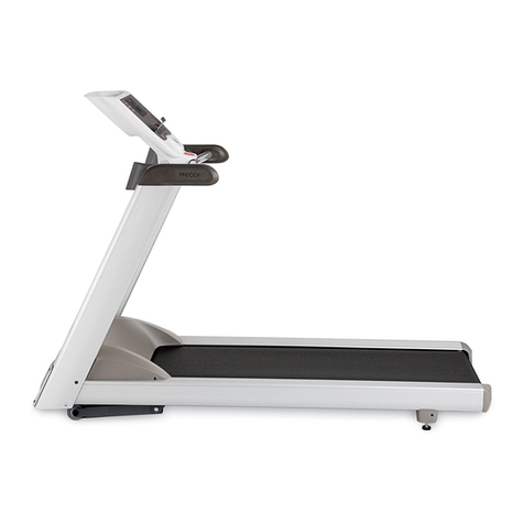
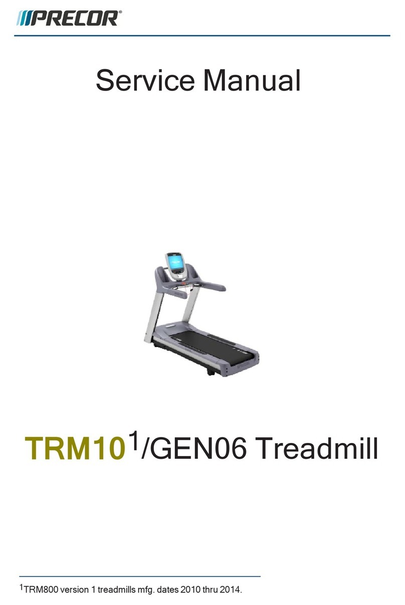
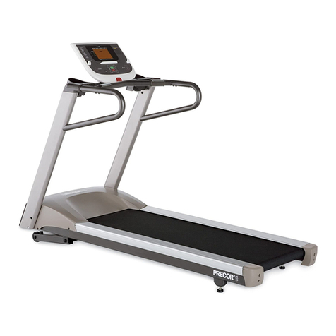
This manual covers service information for the GEN-06 / TRM10 Treadmill
Base.
The GEN-06 treadmill base is defined as any treadmill produced between
April of 2006 and April of 2011. GEN-06 Treadmills include the
following models; C952, C954, C956, and C966.
The TRM10 treadmill base is defined as any treadmill produced after
April 2011 and is mated to a Pxx console. All of the base and console
combinations are part of the "Experience" line of products.
Lubricants
Do not apply any lubricants to the deck and belt. Do not use Wax
Blast, silicon sprays, or other applied lubricants. The use of these
lubricants will quickly degrade the low-friction surface of the deck.
Do not use petroleum based lubricants on mechanical components such as
the lift, as this may result in degradation of nylon gearing
mechanisms. Use only synthetic lubricants such as "Super Lube with
Teflon" or "Mobile One Synthetic" grease (RED).
Use of unapproved lubricants, cleaners, or solvents may void the
treadmill warranty.
Electrical Requirements
It is extremely important that any Precor treadmill be connected to and
operated on a dedicated 20 amp AC branch circuit. A Dedicated Branch
Circuit is defined as a circuit fed by a single circuit breaker feeding a
single load, with a single non-shared neutral providing a return line. A
treadmill operating from a non-dedicated branch circuit or a circuit
breaker of less than 20 amps capacity will not have the necessary power
to operate normally under higher load conditions.
Section 2 - General Information

© Precor Incorporated, Unauthorized Reproduction and Distribution Prohibited by Law Page 7
Nominal AC operating voltage on 120VAC circuits is 90VAC to 132VAC.
Nominal AC operating voltage on 240VAC circuits is 180VAC to 264VAC. For
operator safety considerations and to minimize electrostatic discharge
conditions the AC frame ground continuity must also be verified to be a
low resistance connection to the AC distribution ground bar.
Important
If the AC circuit feeding a treadmill is found to be a non-dedicated
branch circuit or a circuit equipped with a circuit breaker with a
capacity of less than 20 amps, the AC circuit must be corrected before
any reliable troubleshooting can be performed on the treadmill. More
importantly, a non-dedicated branch circuit may constitute a safety
hazard to the treadmill operator.
120 Vac Systems
120 VAC distribution systems utilize a single pole circuit breaker (hot
lead) and a neutral lead connected to a common neutral (ground) bar. The
A.C. safety ground (green wire) is connected to a separate ground bar in
the distribution system.
If it is determined that any of the above electrical conditions are in
question, please consult with a qualified electrician to make appropriate
circuit changes.

© Precor Incorporated, Unauthorized Reproduction and Distribution Prohibited by Law Page 8
Safety guidelines you should know and follow include:
Read the owner’s manual and follow all operating instructions.
Operate the equipment on a solid, level surface.
Visually check the equipment before beginning service or maintenance
operations. If it is not completely assembled or is damaged in anyway,
do not attempt to operate the equipment.
When operating the treadmill:
Do not wear loose clothing. Do not wear shoes with heels or leather
soles.
Check the soles of your shoes and remove any embedded stones.
Tie long hair back.
Do not rock the unit.
Do not stand or climb on the handlebars, display enclosure or cover.
Do not set anything on the handlebars, display enclosure, or cover.
Never place liquids on any part of the treadmill while performing
service.
To prevent electrical shock, keep all electrical components away from
water and other liquids.
Do not use accessory attachments that are not recommended by the
manufacturer-such attachments might cause injuries.
Removing the hood exposes high voltage components and potentially
dangerous machinery. Exercise extreme caution when you perform
maintenance procedures with the hood removed.
Section 3 - Safety Guidelines

© Precor Incorporated, Unauthorized Reproduction and Distribution Prohibited by Law Page 9
This section provides a method of checking the treadmill operation. Check
the treadmill operation at the end of a maintenance procedure and when it
is necessary to ensure that the treadmill is operating properly.
In This Section
Operation Verification ............................ 9
Operation Verification Checklist .................. 11
Operation Verification
Procedure
1 Plug the power cord into the wall outlet and then switch the circuit
breaker to the "ON" position.
2 Press and hold the reset key for at least 6 seconds, if errors are
present the error log will be displayed. Make note of all the errors
in the error log and odometer reading for which the error occurred.
The odometer in the error log can help you determine age and relevance
of the error.
3 Clear the error log.
4 Enter the Hardware Validation test by entering Diagnostic mode as
follows:
5 Press either the STOP, PAUSE or RESET buttons and then enter
5,1,7,6,5,7,6,1
6 Select and run the Display Test, the Keypad Test, and the Heart Rate
Test. Verify the following results.
LEDs light
Keys all function
Heart rate is acquired and displayed
7 Enter the Machine Tests (submenu) and run the Belt Speed test and the
Incline test, verify following results:
Running belt spins and is controlled from 0.1mph to 16.0mph.
Lift goes up and down and the A/D value is approximately 6000+/-500
at 0% incline)
8 Press the reset key to exit diagnostics.
9 Operate the treadmill in the Manual program. Adjust the speed of the
running belt to 2–3mph. Operate the treadmill for at least 5 minutes
while walking on the unit.
Section 4 - Operation Verification

© Precor Incorporated, Unauthorized Reproduction and Distribution Prohibited by Law Page 10
Concentrate on the feel of the running belt, the sound of the drive
motor and rollers. Be on the alert for unusual noises, smells or
vibrations.
Observe the LED’s on the electronic console. Make sure that each LED
lights as the information corresponding to that LED is displayed on
the electronic console.
10 Press the INCLINE key while viewing the electronic console. Confirm
that the running deck inclines and the incline display increments to
15% as the INCLINE key is continually pressed.
11 Press the INCLINE key while viewing the electronic console. Confirm
that the running deck returns to a level position and the incline
display decrements to 0% as the INCLINE key is pressed. (Depending
on the software configuration of the console, the lowest level of
incline might be -3%)
12 While the unit is running and the running belt is in motion, press the
STOP button and verify the running belt stops.
13 Restart the running belt and while the running belt is in motion, pull
the ESTOP cord and verify the running belt stops.
14 Press and hold the reset key for at least 6 seconds and look at the
error log again. This time look for any NEW errors displayed resulting
from the verification test indicating that the unit needs attention.

© Precor Incorporated, Unauthorized Reproduction and Distribution Prohibited by Law Page 11
Operation Verification Checklist
Check, record, and then clear any errors in the error log.
Verify that all LEDs function properly during the Hardware Validation Tests.
Verify that all keys on the keypad function properly during the Hardware Validation Tests.
Verify that the heart rate functions normally and displays a valid heart rate.
Verify the running belt drive system functions properly throughout the minimum to
maximum range of control. All drive system components (deck, belts, rollers, IFT) are free
of excessive noise, vibrations, or smells
Verify the Incline A/D value is approximately 6000+/-500 at 0% incline, the incline operates
within the complete range of the lift when the or keys are pressed and is free of
excessive noise or vibrations.
The STOP button stops the running belt from moving.
Pulling the ESTOP cord stops the running belt from moving.
Check for new errors that may have been recorded in the error log during operation
verification of the treadmill.

© Precor Incorporated, Unauthorized Reproduction and Distribution Prohibited by Law Page 12
In This Section
Service Access Codes .............................. 12
Accessing the Service Software .................... 12
Access Code Table ................................. 14
P20 Console Service Software Access ............... 15
Hardware Validation - Diagnostic Tests (51765761) . 16
Club Parameter - Settings (5651565) ............... 17
Information Display (65) .......................... 18
Service Access Codes
The standardized service access codes are utilized on the following
consoles:
Standard Console
P10 Console
P20 Console
P30 Console
The service codes will allow access to three functional modes, Hardware
Validation, Club Parameters, and a Information Display.
Hardware Validation is a set of functional diagnostic tests that are
useful in troubleshooting problems as well as verifying proper
operation.
Club Parameters are sometimes referred to as Club Settings and are
used to manage usage of the machine.
Information Display is used to access information such as the
odometer, software versions and error logs.
Accessing the Service Software
Accessing these three areas is accomplished the same on all consoles
(Standard, P10, P20, P30) except the P80. To enter Service Software,
press either the STOP, PAUSE, or RESET key (whichever is available on
your specific console) followed by a numeric code for the area of service
software you wish to access.
Section 5 - Standardized Service Access
Codes

© Precor Incorporated, Unauthorized Reproduction and Distribution Prohibited by Law Page 13
The standard access codes use sequential key presses, not simultaneously
holding down multiple keys. The allowable delay between key presses is
short. If too much time is taken between key presses or the wrong key is
pressed, the access procedure will be aborted. If the access is aborted,
it will be necessary to start over from the beginning.
P80 Console
1 Use the System Settings to test your equipment and set parameters that
benefit your users and your facility.
2 The Welcome screen will be the first screen you see when you approach
the P80 console. Press the Pause key and continue holding it down
while you double press (prior to 1.1 version software release) or
single press (1.1 version or after software release) in sequential
order an X configuration on the Volume and Channel key pad (Channel
Up, Volume Down,Volume Up,Channel Down). Release the Pause key
when done pressing the arrows.
Note: The keypad X configuration sequence should be not faster than 1
second between each key stroke. Any speed faster than 1 second may
result in an unsuccessful access to the sign-in screen.
Figure 1: P80 Sign In Access
3 The sign-in screen will be displayed. Type in the technician access
,5,1,7,6,5,7,6,1, and then touch OK. The Settings menu will be
displayed.

© Precor Incorporated, Unauthorized Reproduction and Distribution Prohibited by Law Page 14
Access Code Table
Access Code
Heading Name
Function
5,1,7,6,5,7,6,1
Hardware Validation
Running Diagnostic
Tests
5,6,5,1,5,6,5
Club Parameters
(Commercial)
Changing Machine and
/or Workout Parameters
6,5
Information Display
Acquiring Information

© Precor Incorporated, Unauthorized Reproduction and Distribution Prohibited by Law Page 15
P20 Console Service Software Access
The P20 console starts with STOP, PAUSE, or RESET, however the numeric
values of the service software code is assigned to the function keys in
the absence of the 10-key pad.
Figure 2: P20 Console Access Keys

© Precor Incorporated, Unauthorized Reproduction and Distribution Prohibited by Law Page 16
Hardware Validation - Diagnostic Tests (51765761)
Figure 3: Hardware Validation Graphic

© Precor Incorporated, Unauthorized Reproduction and Distribution Prohibited by Law Page 17
Club Parameter - Settings (5651565)
Safety Code
Eitherenabled ordisabled,thissetting requiresa passw ord
(1234)to be entered in orderto startthe unit.Factory
defaultisdisabled.
SelectLanguage
Setsthe defaultlanguage forALLw orkoutson thism achine.
Language forsingle use w orkoutscan stillbe setby the user
from the w orkoutoptions.
SelectUnits
Setsunitsofm easure (US standard orM etric).Factory
defaultisUS standard.
SetM ax W orkoutTim e
Setsthe m axim um allow able w orkouttim e foreach user.
Factory defaultis60 m inutes.
SetM ax Pause Tim e
Setsthe m axim um tim e thatthe w orkoutcan be paused for.
Factory defaultis120 seconds.
SetM ax CoolD ow n Tim e
Setsthe am ountoftim e thata cooldow n period w illoccurat
the end ofevery w orkout.Factory defaultis5 m inutes.
SetM etricsD efault
Setsa m etricthatm ay be ofspecificim portance to the
specificfacility orfitnesstrainer.The selected m etricw ill
scrollacrossthe screen atregularintervalsduring the
w orkout. Factory default is “N O N E”
SetSpeed Lim it
Setsthe m axim um speed thatthe usercan setthe unitto.
Factory defaultis16m ph.
SetIncline Lim it
Setsa m axim um value thatthe usercan setthe incline to.
Factory defaultis15% .
Show H idden Program s
Eitherenabled ordisabled,thissetting allow sthe unitto
accessspecialized fitnesstestsdesigned forpolice,fire
fighters,and the m ilitary.Factory defaultisdisabled.

© Precor Incorporated, Unauthorized Reproduction and Distribution Prohibited by Law Page 18
Information Display (65)
O dom eter
D isplaysthe totalnum berofaccum ulated m ileson the unit.Thisvalue
isstored in the upperPCA in the console,so ifthe PCA isreplaced the
accum ulated m iles w ould start again from “0”.
H oursofUse
D isplaysthe totalnum berofhoursthatthe unittookto accum ulate
those m ilesunit.Thisvalue isstored in the upperPCA in the console,so
if that PCA is replaced the hours of use w ould start again from “0”
UpperBootSoftw are
D isplaysthe currentversion ofsoftw are thathandlesflash upgradesof
upperPCA (console)softw are.
UpperBase Softw are
D isplaysthe currentversion ofsoftw are loaded in the upperPCA
(console).Thisisthe unitspecificconsole softw are.
Low erSoftw are
D isplaysthe currentversion ofsoftw are loaded in the low ercontrol
m odule (IFT drive).
M etricsBoard Softw are D isplaysthe currentversion ofsoftw are loaded in the m etricsboard.
SerialN um ber
The base serialnum bercan be sethere using theW inCSAFE com puter
softw are.Factory defaultisN O N E.
Usage Log
D isplaysthe type ofw orkoutprogram sthe usersare accessing m ost
frequently.
ErrorLog D isplaysa running log ofthe last10 errorsencountered on the unit.
Table of contents
Other Precor Treadmill manuals

Precor
Precor M9.41si User manual

Precor
Precor M9.21i User manual

Precor
Precor C966i User manual

Precor
Precor 9.31 User manual

Precor
Precor M9.55 User manual

Precor
Precor C932i User manual

Precor
Precor 904 User manual

Precor
Precor M9.20 User manual

Precor
Precor Experience TRM700-16 User manual

Precor
Precor TRM 800 Assembly Instructions

Precor
Precor 9.23 User manual

Precor
Precor 905e User manual

Precor
Precor Cycles Integrated LCD Screen Option none User manual

Precor
Precor C952i User manual

Precor
Precor C954 Instruction manual

Precor
Precor Treadmill EFX534 User manual

Precor
Precor Experience 800 User manual

Precor
Precor 9.25 User manual

Precor
Precor C954 User manual

Precor
Precor ENERGY SERIES User manual