Precor Treadmill EFX534 User manual

Light Commercial EFX®Owner’s Manual
COMMERCIAL PRODUCTS DIVISION

page 2
COMMERCIAL PRODUCTS DIVISION
When using the EFX®, basic precautions should always be followed, includ-
ing the following:
• To ensure your safety and to protect the unit, read all the instructions
before assembling and using the self-powered EFX®534.
• To ensure the proper use and safety of the EFX, make sure that all users
read this manual. Please make this manual a part of your staff’s training
program. Remind the users that before beginning any fitness program,
he or she should obtain a complete physical examination from his or her
physician.
Il est conseillé de subir un examen médical complet avant d’entre-prendre
tout programme d’exercise. Si vous avez des étourdissements ou des
faiblesses, arrêtez les exercices immédiatement.
DANGER —
WARNING —
• Do not allow children or those unfamiliar with its operation on or near
the EFX. Do not leave children unsupervised around the EFX.
• Never leave the EFX unattended with the optional battery recharger
plugged in. Unplug the unit from the outlet when it is not in use, before
cleaning it, and before putting on or taking off parts.
• Assemble and operate the EFX on a solid level surface. Locate the EFX
a few feet from walls or furniture. Check the unit before each use and
verify that all fasteners are secure. Maintain the EFX in good working condi-
tion. (See the
Maintenance
section).
• Use the EFX only for its intended use as described in this manual. Do
not use accessory attachments that are not recommended by the manu-
facturer—such attachments might cause injuries.
• Use care when getting on or off the EFX. Use the stationary handrail
whenever possible. Keep your body and head facing forward. Never
attempt to turn around on the EFX.
• Wear proper exercise clothing and shoes during a workout—no loose
clothing.Tie long hair back.
• Do not rock the unit. Do not stand on the display console or casing.
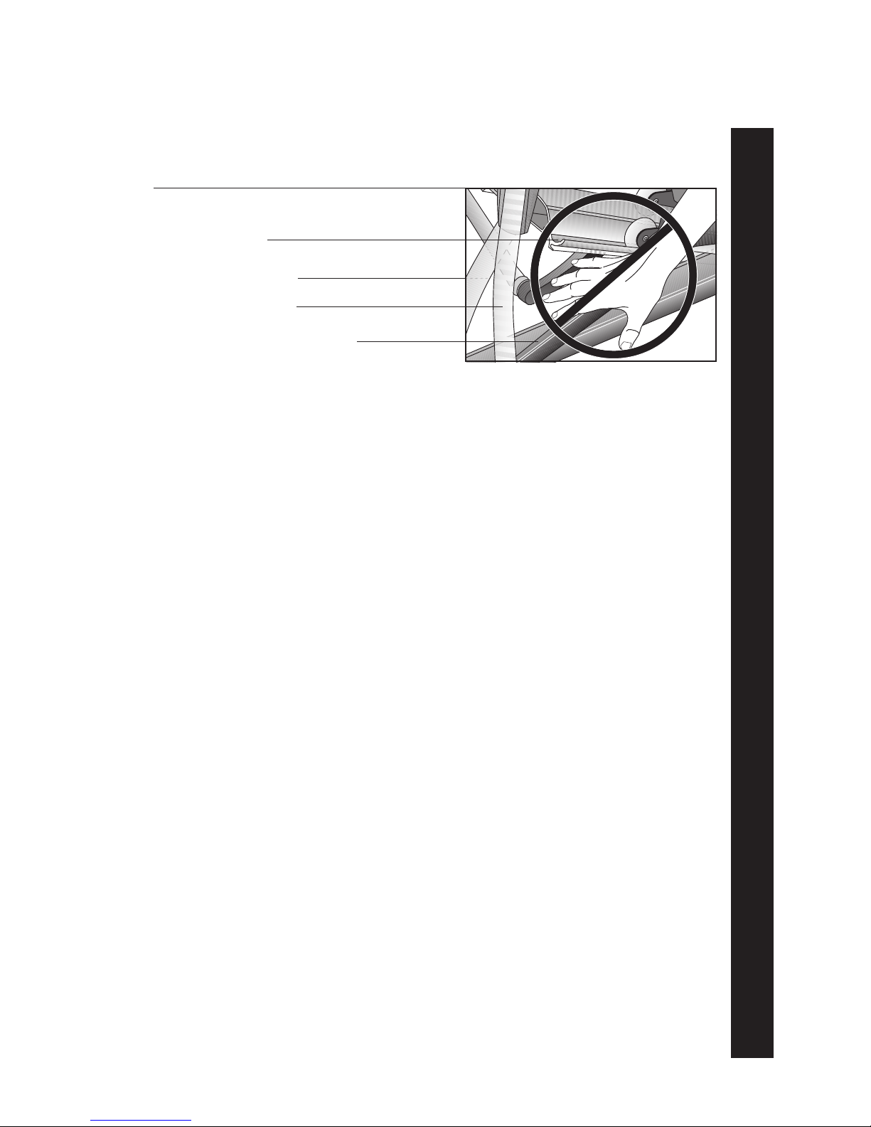
• Never drop or insert any object into any opening. Keep towels and
hands away from moving parts.
• If you purchased the optional POLAR®chest strap, review the guide-
lines found in the
Precor Heart Rate Option Owner’s Manual
that is
supplied with that option.
• Do not overexert yourself or work to exhaustion. If you feel any pain or
abnormal symptoms, stop your workout immediately and consult your
physician.
•Keep all electrical components away from liquids to prevent shock. Do not
set anything on the casing, handrails, or display console. Place liquids
only in the appropriate receptacles.
IMPORTANT SAFETY INSTRUCTIONS
To reduce the risk of electrical shock, always unplug the
optional battery recharger from its power source before clean-
ing or performing any maintenance tasks.
To reduce the risk of burns, fire, electric shock, or injury to
persons, take the following precautions:
IMPORTANT SAFETY INSTRUCTIONS

page 3
COMMERCIAL PRODUCTS DIVISION
• Never place your hand(s) or feet in the path of the roller arm because
injury may occur to you or damage may occur to the equipment. Refer
to Diagram 1.
• Never operate the unit if it is damaged, if it is not working properly, if it
has been dropped, or dropped in water. Return the unit to a service
center for examination and repair.
• Keep the optional battery recharger cord away from heated surfaces.
• Do not operate where aerosol (spray) products are being used or where
oxygen is being administered.
• Do not use outdoors.
• Do not attempt to service the EFX yourself other than the assembly and
maintenance instructions found in this manual. Refer to
Obtaining Service
.
HAZARDOUS MATERIALS AND PROPER DISPOSAL
The EFX534 has an internal battery which must be removed before the EFX is
scrapped.The battery contains materials which are considered hazardous to the
environment. Proper disposal of the battery is required by federal law.
To remove the battery from the EFX, take the following steps:
CAUTION: Unplug the battery recharger and disconnect it from
its receptacle at the rear of the EFX.
Tools required: Phillips head screwdriver and hex wrench set.
1. Remove both the right and left rear covers from the EFX.
2. Remove the top rear cover.
3. Unplug the black and red battery wires from the circuit board.
4. Separate the circuit board from the battery by removing four screws.
5. The battery is held in place with a metal bracket. Lift the battery away from
the bracket.
6. Dispose of the battery according to the federal Hazardous Waste Regulations.
SAFETY APPROVAL
When identified with the ETL-c logo, the EFX has been tested and conforms to
the requirements of CAN/CSA-E-335-1/3-94, Safety of Household and Similar
Electrical Appliances.
IMPORTANT SAFETY INSTRUCTIONS
SAVETHESE INSTRUCTIONS
Diagram 1
Avoid injury from the roller
arm mechanism.
Front cover
Handlebar
Lower pivot roller arm
(handlebar linkage)
Ramp

page 4
COMMERCIAL PRODUCTS DIVISION
Important Safety Information ...........................................2
Hazardous Materials and Proper Disposal .............................. 3
Safety Approval ..................................................................... 3
RFI — Radio Frequency Interference ..................................... 6
European Applications ........................................................... 6
EFX®Self-powered Features .................................................. 7
Obtaining Service ................................................................... 7
About this Manual .................................................................. 8
Unpacking the EFX®.................................................................................................. 9
Standard Equipment ............................................................... 9
Other Equipment .................................................................... 9
Acquiring the Appropriate Tools .............................................. 9
Hardware Kit .......................................................................... 10
Setting Up the EFX .........................................................11
Installation Requirements ....................................................... 11
Assembly Instructions ........................................................... 11
Removing the Locking Pin...................................................... 21
Supplying Power To the EFX534 ............................................. 22
Testing the Heart Rate Display ............................................... 22
Custom Setting Mode ....................................................23
Changing the Custom Settings ............................................... 23
Determining the Units of Measure .......................................... 24
Setting a Workout Time Limit.................................................. 25
Setting a Pause Time Limit .................................................... 25
Viewing the Odometer, Hours of Use,
Software Version, and Error Log ............................................. 25
Using CSAFE Standard Equipment ........................................ 26
The EFX®534 Display .....................................................27
Features on the Display Console ............................................ 27
User Setup Prompts ............................................................... 28
Using QuickStart During the Setup Prompts .......................... 29
Center Display........................................................................ 30
SmartRate®Display ............................................................... 31
Informational Displays Prior to Shutdown ............................... 31
Keys on the Display Console.................................................. 32
Table of Contents

page 5
COMMERCIAL PRODUCTS DIVISION
Table of Contents
Exercising on the EFX®..................................................................................... 34
The Heart Rate Feature .......................................................... 34
Utilizing the SmartRate®Feature ............................................ 34
Removing the Locking Pin...................................................... 35
Workout Tips .......................................................................... 35
Using the Handlebars ............................................................. 36
Using the Stationary Handrail ................................................. 36
Changing the Display Features using the Select Key ............. 36
Quick Steps to Working Out ................................................... 37
Cooling Down After a Workout ................................................ 38
Pause, Cool Down and Exit Features ..................................... 38
Inserting the Locking Pin ....................................................... 39
Courses...........................................................................40
Manual Mode and the QuickStart Key .................................... 40
Hill Climb Course ................................................................... 40
Interval Course ....................................................................... 40
Cross Training Course ............................................................. 41
Weight Loss Course ............................................................... 42
Maintenance ...................................................................43
Inspection .............................................................................. 43
Cleaning the Equipment ......................................................... 43
Storing the POLAR®Chest Strap ........................................... 44
Servicing the EFX and Long Term Storage ............................. 44
Symptoms of a Low Battery ................................................... 44
Using the Battery Recharger and Its Power Cord .................... 44
Replacing the Battery ............................................................. 45
Battery Recharger Power Cord ............................................... 45
Exploded Views ...................................................................... 46
Warranty Registration Card ..................................................... 53
Warranty ................................................................................. 55
Specifications ............................................................back cover

page 6
COMMERCIAL PRODUCTS DIVISION
RFI — RADIO FREQUENCY INTERFERENCE
Federal Communications Commission Part 15
The EFX has been tested and found to comply with,
• the IEC EMC Directive (international electromagnetic compatibility certification)
• the limits for a Class A digital device, pursuant to Part 15 of the FCC Rules.
These limits are designed to provide reasonable protection against harmful
interference in a commercial installation. The EFX generates, uses, and can
radiate radio frequency energy and, if not installed and used in accordance
with the owner’s manual instructions, may cause harmful interference to radio
communications. Operation of the EFX in a residential area is likely to cause
harmful interference. If this occurs, the user will be required to correct the
interference at his or her own expense.
CAUTION —
Canadian Department of Communications
This digital apparatus does not exceed the Class A limits for radio noise emissions
from digital apparatus set out in the Radio Interference Regulations of the Canadian
Department of Communications.
Le présent appareil numérique n’émet pas de bruits radioéélectriques dépassant les
limites applicables aux appareils numériques de la Class A prescrites dans le
Règlement sur le brouillage radioélectrique édicté par le ministére des Communica-
tions du Canada.
EUROPEAN APPLICATIONS
This product conforms to the requirements of the European Council Directive 89/336/
EEC, Electromagnetic Compatibility and has been tested to the following standards:
EN55022, Limits & Methods of Measurement of Radio Interference, Information
Technology Equipment (Class A).
EN50082-1, Generic Immunity Standard for Residential, Commercial and Light
Industrial Products (Class A).
This product additionally conforms to the requirements of the European Council Directive
73/23/EEC, Low Voltage Directive and has been tested to the following standard:
IEC 335-1, Safety of Household and similar Electrical Appliances.
European Applications
This product has been tested to the requirements of EN55022, “Limits & Methods of
Measurement of Radio Interference, Information Technology Equipment.” Per that
standard, the EFX534 is a Class A product. In a domestic environment, this product
may cause radio interference, in which case the user is responsible to take adequate
measures to alleviate the interference.
Per FCC rules, changes or modifications to the EFX
not expressly approved by Precor, could void the
user’s authority to operate the equipment.

page 7
COMMERCIAL PRODUCTS DIVISION
EFX®SELF-POWERED FEATURES
The power source for the EFX is the user.When a person works out on the EFX and
moves the foot pedals at a stride rate above 40 strides per minute, the power that
is generated allows the EFX to function properly.
Informational displays appear when the battery is low or when the user has stopped
pedaling during a workout. The display provides minimal instructions to let you
know what to do to retain power. If the messages are ignored, the EFX will begin
shutdown procedures to maintain the charge of the battery. Refer to page 31,
Informational Displays Prior to Shutdown
.
An optional battery recharger can be purchased and provides sustained power to
the EFX. If you plan to customize your unit, the optional battery recharger is highly
recommended.To purchase the optional battery recharger, check with your dealer.
OBTAINING SERVICE
Do not attempt to service the self-powered EFX®yourself except for the mainte-
nance tasks described in this manual. The EFX does not contain any user-service-
able parts. For information about product operation or service, contact an authorized
Precor Commercial Products Customer Support Representative at 1-888-665-4404.
Diagram 2
EFX serial number location.
Serial number label location
To help Customer Support personnel expedite your call, have your serial number
available.The serial number can be found on a label near the power receptacle on
the rear cover. Refer to Diagram 2. If you have any questions regarding the EFX,
use the model and serial numbers whenever you call your Precor dealer or servicer.
Model number: EFX®534
Unit number: _____ Serial number: _____________________________

page 8
COMMERCIAL PRODUCTS DIVISION
ABOUT THIS MANUAL
Inside this manual, you will find instructions for installing and using the self-powered
EFX. To maximize the use of the EFX, please study this manual thoroughly. The
manual uses the following conventions for identifying special information:
Note: Contains additional information.
Important: Indicates information to which you should pay special attention.
CAUTION: Indicates steps or information necessary to prevent harm to your-
self or damage to the equipment.
WARNING — Provides instructions to prevent electrical damage to
the equipment and prevent injuries to yourself.
DANGER — Indicates steps you must take to prevent electrical shock.

page 9
COMMERCIAL PRODUCTS DIVISION
Thank you for purchasing the self-powered Precor EFX®534.
Important: Before using the EFX, we urge you to familiarize yourself and your
staff with the entire Owner’s Manual. Understanding this manual will help you and
your customers use the EFX safely and successfully.
Your EFX is carefully inspected before shipment so it should arrive in good operating
condition. Precor ships the unit in the following pieces:
❑Base frame assembly ❑Base frame stabilizers (left and right)
❑Upright support ❑Display console
❑Handlebars (left and right) ❑Bracket cover
❑Hardware kit and owner’s manual
CAUTION: This unit weighs over 230 pounds (105 kilograms). To prevent
injury to yourself or damage to the equipment, obtain appropriate assistance
before removing the unit from the pallet.
If any items are missing, contact your Precor Commercial Products Service Repre-
sentative at 1-888-665-4404.
STANDARD EQUIPMENT
The EFX®534 incorporates the Precor SmartRate®and Heart Rate features into its
display console. Devices, such as FitLinxx®, that are CSAFE compatible, can also
be attached.
Note: An optional POLAR® chest strap can be purchased and worn during a workout.
The chest strap transmits the user’s heart rate to the display console’s receiver.
OTHER EQUIPMENT
Optional equipment available through your dealer includes:
• Battery recharger
• POLAR®chest strap.
If you are interested in obtaining Precor option kits for your unit, check with your
dealer. For Customer Support, see
Obtaining Service
on page 7.
ACQUIRING THE APPROPRIATE TOOLS
Obtain the following tools
before
assembling the EFX.
❑Wire cutter ❑Phillips head screwdriver
❑Rubber mallet ❑Hex torque wrench
❑Two 9/16" combination wrenches (open-end and box)
❑SAE Standard socket set with socket extension for 1/2” and 9/16" bolts
Unpacking the EFX®

page 10
COMMERCIAL PRODUCTS DIVISION
Diagram 3
EFX534
Hardware kit
HARDWARE KIT
Carefully unpack the parts from the shipping container. Open the Hardware Kit
and make sure that you have the following items as shown in Diagram 3:
❑(A) 5/16-inch hex key — secures handlebars
❑(B) End cap
❑(C) Two shoulder bolts — install handlebars to lower pivot arms
❑(D) Four Phillips-head screws — attach display console
❑(E) Six 1-inch long x 5/16-inch diameter bolts — attach handlebars
❑(F) Six small diameter washers — use with 5/16-inch bolts (E)
❑(G) Eighteen 1-inch long x 3/8-inch bolts — attach upright and stabilizers to base
❑(H) Eighteen large diameter washers — use with 3/8-inch bolts (G)
❑(J) Height adjustor
If any items are missing, contact your dealer. If you need Customer Support,
refer to
Obtaining Service
on page 7.
Note: After assembling the EFX, be sure to store the hex key in a secure place.
The tool is used for maintenance procedures that are described in this manual.
B
A
C
DE
F
H
G
J

page 11
COMMERCIAL PRODUCTS DIVISION
You do not need any special knowledge or experience to set up the EFX. However,
because of the size and weight of the EFX, you will need to obtain appropriate
assistance during assembly.
INSTALLATION REQUIREMENTS
Follow these installation requirements when installing the EFX.
If you do not
install the EFX according to the following guidelines, you could void the Precor
Limited Warranty.
•Set up the EFX on a solid, flat surface. Unpack and assemble the EFX close to
where you’ll use it. Make sure that the flat surface under the unit is smooth and
level. A level unit is required for the user’s safety and for proper operation.
•Provide ample space around the unit. Open space around the unit makes
for a safer mount and dismount.
•Fill out and mail the limited warranty card.The serial number is located on
a label at the rear of the unit near the optional battery recharger receptacle.
Write the serial number onto the Precor Limited Warranty card found on the
back cover of this manual. Refer to
Obtaining Service
on page 7 and write the
number there as well.
ASSEMBLY INSTRUCTIONS
To assist you in the assembly, the items in the Hardware kit, shown in Diagram 3,
correspond to a particular letter in the alphabet. These letters appear throughout the
assembly instructions. Refer to Diagram 3 on page 10.
1. Obtain assistance. Place the shipping carton close to the location where
you plan to use the unit. Break down the side walls so that they lie flat. You
may need to cut the tie wraps that hold the base frame and roller arms to the
pallet.
2. Unpack the EFX534. Remove the packing materials and loose contents. Refer
to the list on page 9.
3. Move the unit to the location where you plan to use it. Once you attach
the handrails and base stabilizers, the EFX is difficult to move through a
standard door frame. Make sure to assemble the unit where it will not have to
be moved through any doorways.
CAUTION: Do not assemble the EFX if it is connected to the optional
battery recharger. Remove the battery recharger from the EFX prior to
assembly.
Setting Up the EFX®

page 12
COMMERCIAL PRODUCTS DIVISION
2
Diagram 4
4. Cut the tie wrap securing the front base tube to the pallet. Discard the tie
wrap.
5. Thread the height adjustor to its lowest position. Diagram 4, #1 and #2.
Remove the height adjustor from the Hardware kit. Ask an assistant to lift the
front base tube while you insert the height adjustor.Turn the height adjustor so
that the threads appear inside the base tube.Tighten the nut (with a crescent
wrench) when the height adjustor is fully threaded into the front base tube.
6. Cut the tie wrap holding the plastic grommet. Diagram 4, #3. Use a wire
cutter (or scissors) to remove the plastic grommet from the cable.
Front base assembly.
Cut the tie wrap that
secures the grommet
to the cable.
Height adjustor
Front base tube
3
Tighten the height
adjustor so that the
nut is secure against
the front tube.
Diagram 5
Front base assembly.
Plastic grommet
Front base assembly
Cable receptacle
1
7. Insert the plastic grommet. Diagram 5. Place the grommet into the hole on
the front base assembly. Press down so that it snaps into place.
Plastic grommet

page 13
COMMERCIAL PRODUCTS DIVISION
8. Prepare for the attachment of the upright support to the base assembly.
Diagrams 6 and 7. Remove the four phillips-head screws (D), two bolts (G),
and two washers (H) from the Hardware kit. Place one washer (H) on each of
the two bolts (G). Keep the fasteners together.
CAUTION: Do not stretch, crimp, or damage the cable. Excess cable may
be gently pushed into the base assembly. Cables damaged by improper
installation will not be covered by the Precor limited warranty.
9. Route the display console cable through the upright support. Diagram 6, #1
Remove any tape or wire ties on the cable. Have an assistant hold the upright
support securely while you grasp the display console in one hand and route the
cable through the upright support with the other.
10. Attach the display console. Diagram 6, #2. Use the four phillips-head
screws (D) to attach the display console to the upright support. Have your
assistant hold the upright support securely while you align the mounting holes
and tighten the screws.
Diagram 6
Route the cable and
attach the display
console to the
upright support.
Display console
Upright support
Cable
2
1

page 14
COMMERCIAL PRODUCTS DIVISION
11. Position the upright support over the base. Diagram 7. Have your assistant
move the upright support close to the front of the base assembly while you
thread the cable through the grommet hole and out the front of the base tube
(see inset #1). Make sure that the display console (on the upright support)
faces the rear of the unit (see inset #2).
CAUTION: As you assemble the unit, do not fully tighten the fasteners until
instructed to do so. Finger tighten the fasteners or use the hex key so that
the unit is stable, but the fasteners still allow room for adjustments.
12. Secure the upright support to the base assembly. Diagram 7. Align the
mounting holes and thread the two bolts (G) with washers (H) through opposite
sides of the upright support and into the base assembly. Finger tighten each
bolt. Do not fully tighten the fasteners until the entire unit has been assembled.
Diagram 7
Route the cable
through the grommet
and attach the upright
support.
Cable connector
Have your assistant
hold the upright
support while you
secure it to the base.
2
1
Two bolts (G)
with washers (H)
Cable receptacle
Upright
support
Base
assembly
Diagram 8
Connect the
cables.
Cable connector
Cable receptacle
Place excess cable
into the base tube.
Height adjustor
threads
Base tube
Base tube

page 15
COMMERCIAL PRODUCTS DIVISION
13. Connect the cable. Diagram 8, inset. Insert the cable into its receptacle.
Just like a telephone connection, a definite "click" is heard when a good
connection is made. If you do not hear a "click," try reinserting the cable
connection again.
14. Push excess cable inside base tube. Diagram 8. Carefully, push any excess
cable behind the height adjustor threads that protrude from inside the base tube.
15. Rotate the rear pads. Diagram 9, inset. Ask your assistant to stabilize the
unit while you rotate the rear adjustable pad to the highest position. This
procedure lifts the base assembly off the floor which provides better access
to the fasteners.
16. Place the base assembly on the supportive wedge. Diagram 9. Have an
assistant grasp and lift the upright support so that you can slide a wedge
(packing material) under the front of the unit.
Diagram 9
Place the base
on supportive
blocks.
Adjustable rear pad
Supportive
wedge
Base assembly

page 16
COMMERCIAL PRODUCTS DIVISION
17. Attach the left and right frame stabilizers. Diagram 10. Proceed with one
side at a time.When you have installed the first stabilizer, perform the same
steps on the opposite stabilizer.
a. Remove four bolts (G) and four washers (H) from the Hardware kit. Place
a washer on each bolt and set the fasteners within easy reach of the unit.
b. Grasp one of the frame stabilizers and align it with the upright support bracket.
c. Insert the four bolts (G) with washers (H) through the frame stabilizer and
upright support bracket. See Diagram 10.
d. Thread all four bolts and washers until the frame stabilizer is secure. Do
not fully tighten the bolts until after the lower section is attached.
e. Perform steps a through d on the opposite side.
Diagram 10
Attach the frame
stabilizers to the
upright support
brackets.
Bolts (G) and
washers (H)
Frame stabilizer
Upper section
Lower section
Upright
support
bracket
Diagram 11
Attach the lower
frame stabilizers
to the base
assembly.
Bolts
f. Carefully, align the mounting holes on the right and left frame stabilizer with
the base frame holes. Insert four bolts (G) and washers (H) on both sides.
Thread the bolts through the unit. See Diagram 11.You may need to adjust
and gently move the stabilizers up and down to get the mounting holes on
both sides of the base frame properly aligned.
g. Tighten the bolts so that the unit is stable, but leave room for final adjustments.
Do not securely tighten the bolts until the unit has been fully assembled.

page 17
COMMERCIAL PRODUCTS DIVISION
18. Tighten all mounting screws using a 9/16" wrench. Diagram 12.
a. Ask for assistance to remove the supportive wedge from beneath the base
assembly and to turn the unit onto its side.
b. With the unit on its side, start at the base with the eight bolts that attach the
frame stabilizers to the base frame. Tightening these bolts first helps pull
the rest of the parts into alignment. Proceed with securely tightening the
bolts attached to the upright support bracket and the bolts that secure the
upright support to the base frame.
Tighten the bolts
on the base
frame first.
Diagram 12
Tighten the
mounting bolts.
2
3
1
Upright support
bracket
Left frame stabilizer
Base frame
Upright support

page 18
COMMERCIAL PRODUCTS DIVISION
19. Attach the left and right handlebars. Diagram 13. Perform the following
steps on one side of the unit and then, repeat the steps on the opposite side.
a. Remove the three bolts (E) and washers (F) from the Hardware kit. Place
the washers on the bolts.
b. Attach one handlebar at a time. Note that the handlebars’ mounting holes
are smooth on one side and slightly protrude on the other side. Place the
protrusions against the handlebar brackets.
c. Align the holes and insert the three bolts (E) and washers (F).Thread the
bolts (E) into the holes using your fingers.
d. Tighten the bolts securely using a 1/2-inch socket wrench.
e. Repeat steps a. through d. to secure the opposite handlebar.
Diagram 13
Secure the
handlebars.
Protrusions
Handlebar
bracket
Tighten bolts securely.
Diagram 14
Secure the
handlebars to the
pivot arm.
Shoulder bolt (C)
Handlebar
5/16-inch hex key
Pivot arm

page 19
COMMERCIAL PRODUCTS DIVISION
Diagram 15
Secure the
bracket cover.
Bracket cover
Upright support
bracket
20. Attach the handlebars to the pivot arm. Diagram 14. Proceed with one
handlebar at a time.When you have completed the installation steps for one,
perform the same steps for the opposite handlebar.
a. Remove the shoulder bolt (C) from the Hardware kit.
b. For ease of installation, slide the foot pedal to the top of the ramp.
c. On the same side, align the mounting holes on the handlebar and the
pivot arm.
d. Insert the shoulder bolt. Secure the handlebar to the lower pivot arm using
the hex key provided.Tighten the bolt securely. See Diagram 14.
21. Attach the bracket cover. Diagram 15.Take the following steps to attach the
cover over the upright support bracket.
CAUTION: Do not overtighten the screws or you may inadvertently cause
stress cracks in the plastic.
a. Move the handlebars out of the way.
b. Locate the two screws beneath the upright support bracket. Remove each
one using a phillips head screwdriver.
c. Place the bracket cover over the upright support and align the mounting
holes. See Diagram 15.
d. Insert the two screws through the bracket mounts and into the side of the
upright support bracket. Tighten the screws. Do not tighten too much or
you may inadvertently crack the plastic mounts.
Remove screws from
beneath the upright
support bracket.

page 20
COMMERCIAL PRODUCTS DIVISION
22. Level the unit. Diagram 16.To keep the unit stable, the EFX has adjustable
rear pads and, at the front of the base assembly, a height adjustor. Check to
make sure that the unit does not wobble from side to side or front to back.
Important: If the unit is placed on a slightly, uneven surface, adjusting the
rear pads can help, but will not compensate for extremely uneven surfaces.
a. To remove any side to side movement or wobble, rotate the rear pads.
b. To counteract any rocking (front to back) motion, ask your assistant to
grasp the upright support so that he or she can raise the front of the unit
off the floor. Use a crescent or combination wrench to loosen the nut.
• Turn the height adjustor clockwise to raise the height of the front end.
• Turn the height adjustor counterclockwise to lower the height.
Once you have the proper height adjustment, use the wrench to turn the
nut counterclockwise and tighten it securely against the base tube.
Diagram 16
Level the unit.
Height adjustor
Rotate rear
adjustment pads.
Rear crossbar
Base tube
Nut
Diagram 17
Clean the ramp.
Roller
Wipe ramp with a
damp, clean cloth.
Ramp
Foot pedal
23. Clean the ramp. Diagram 17. Wipe down the ramp and foot pedals with a
soft cloth dampened in a diluted solution of mild soap and water.
Table of contents
Other Precor Treadmill manuals

Precor
Precor C932i User manual

Precor
Precor TRM10/GEN06 User manual

Precor
Precor 9.23 User manual

Precor
Precor M9.41si User manual

Precor
Precor 9.23 User manual

Precor
Precor 9.25 User manual

Precor
Precor TRM 425 User manual

Precor
Precor TRM. 600 User manual

Precor
Precor M9.45 User manual

Precor
Precor 903 User manual

Precor
Precor Experience 800 User manual

Precor
Precor 9.41s User manual

Precor
Precor ENERGY SERIES User manual

Precor
Precor C934 User manual

Precor
Precor C932 User manual

Precor
Precor Experience 700 line Series User manual

Precor
Precor C954 Instruction manual

Precor
Precor 9.35 Owner's manual

Precor
Precor TRM 800 Assembly Instructions

Precor
Precor 9.31 User manual