Midea RG15A1/E User manual

without prior notice for product improvement.
Consult with your dealer or manufacturer for details.
For more information, please visit our website www.midea.com.ph
A quality product of
Window Type Inverter Model
Customer Care
(02) 863-55-22
Landline:
0917-8425555
SMS:
1-800-10-863-5522
Toll free:
Email: customercare@midea.com.ph

CONTENTS
1. SAFETY PRECAUTIONS..............................................................................................................................
2. UNIT PARTS IDENTIFICATION .................................................................................................................
3. AIR CONDITIONER FEATURES ................................................................................................................
4. HANDLING THE REMOTE CONTROLLER.............................................................................................
5. INSTALLATION INSTRUCTIONS...............................................................................................................
6. CARE AND CLEANING................................................................................................................................
7. TROUBLESHOOTING TIPS..........................................................................................................................
2
5
6
8
14
17
18
Inside you will find many helpful hints on how to use and maintain your air conditioner
properly. Just a little preventive care on your part can save you a great deal of time and
money over the life of your air conditioner. You’ll find many answers to common
problems in the chart of troubleshooting tips. If you review our chart of Troubleshooting
Tips first, you may not need to call for service at all.
This appliance can be used by children aged from 8 years and above and persons with
reduced physical, sensory or mental capabilities or lack of experience and knowledge if
they have been given supervision and instruction concerning use of the appliance in a
safe way and understand the hazards involved. Children shall not play with the
appliance. Cleaning and maintenance shall not be done by children without supervision.
If the supply cord is damaged, it must be replaced by the manufacturer, its service agent
or similarly qualified persons in order to avoid hazard.
The appliance shall be installed in accordance with national wiring regulations.
Do not operate your air conditioner in a wet room such the bathroom or the laundry
room.
Contact Midea Customer Care for repair or maintenance of this unit.
READ THIS MANUAL
CAUTIONS

OTHER TIPS(be applicable for R32 refrigerant)
WARNING(be applicable for R32 refrigerant)
Do not use means to acclerate the defrosting process or to clean,other than those
recommended by manufacturer.
The appliance shall be stored in a room without continuously operating ignition
sources(for example:open flames,an operating gas appliance or an operating
electric heater).
Do not pierce or burn.
Be aware that the refrigerants may not contain the odour.
Appliance should be installed,operated and stored in a room with a floor area larger
than 4m2.
Compliance with national gas regulations shall be observed.
Keep ventilation openings clear of obstruction.
The appliance shall be stored so as to prevent mechanical damage from occuring.
A warning that the appliance should be stored in a well ventilated area where the
room size coresponds to the room area as specified for operation.
Any person who is involved with working on or breaking into the refrigerant circuit
should hold a current valid certificate from an industry-accredited assessment
authority,which authorises their competence to handle refrigerants safely in
accordance with an industry recognised assessment specification.
Servicing shall only be performed as recommended by the equipment
manufacturer.Maintenance and repair requiring the assistance of other skilled
personnel shall be carried out under the supervision of person competent in the
use of flammable refrigerants.
1.Transport of equipment containing flammable refrigerants
See transport regulations
2.Marking of equipment using sighs
See local regulations
3.Disposal of equipment using flammable refrigerants
See national regulations.
4.Storage of equipment/appliances
The storage of equipment should be in accordance with the manufacturer's instructions.
5.Storage of packed(unsold) equipment
Storage package protection should be constructed such that mechanical damage to the
equipment inside the package will not cause a leak of the refrigerant charge.
The maximum number of pieces of equipment permitted to be stored together will be
determined by local regulations.
6.Information on servicing
1)Checks to the area
Prior to beginning work on systems containing flammable refrigerants,safety checks are
necessary to ensure that the risk of ignition is minimised.For repair to the refrigerating
system,the following precautions shall be complied with prior to conducting work on the
system.
2)Work procedure
Work shall be undertaken under a controlled procedure so as to minimise the risk of a
flammable gas or vapour being present while the work is being performed.
3)General work area
All maintenance staff and others working in the local area shall be instructed on the
nature of work being carried out.Work in confined spaces shall be avoided.The area
around the workspace shall be sectioned off.Ensure that the conditions within the area
have been made safe by control of flammable material.
4)Checking for presence of refrigerant
The area shall be checked with an appropriate refrigerant detector prior to and during
work,to ensure the technician is aware of potentially flammable atmospheres.Ensure
that the leak detection equipment being used is suitable for use with flammable
refrigerants.i.e.non-sparking adequately sealed or intrinsically safe.
5)Presence of fire extinguisher
If any hot work is to be conducted on the refrigerantion equipment or any associted
parts,appropriate fire extinguishing equipment shall be available to hand,Have a dry
powder or CO2 fire extinguisher adjacent to the charging area.
6)No ignition sources
No person carrying our work in relation to a refrigeration system which involves
exposing any pipe work that contains or has contained flammable refrigerant shall
use any sources of ignition in such a manner that it may lead to the risk of fire or
explosion.All possible ignition sources,including cigarette smoking,should be kept
sufficiently far away from the site of installation,repairing,removing and disposal,
during which flammable refrigerant can possibly be released to the surrounding
space.Prior to work taking place,the area around the equipment is to be surveyed
to make sure that there are no flammable hazards or ignition risks."No Smoking"
signs shall be displayed.

SAFETY PRECAUTIONS
!
WARNING
It may cause electric shock.
!
!
!
!
!
!
To prevent injury to the user or other people and property damage, the following instruc-
tions must be followed. Incorrect operation due to ignoring of instructions may cause
harm or damage. The seriousness is classified by the following indications.
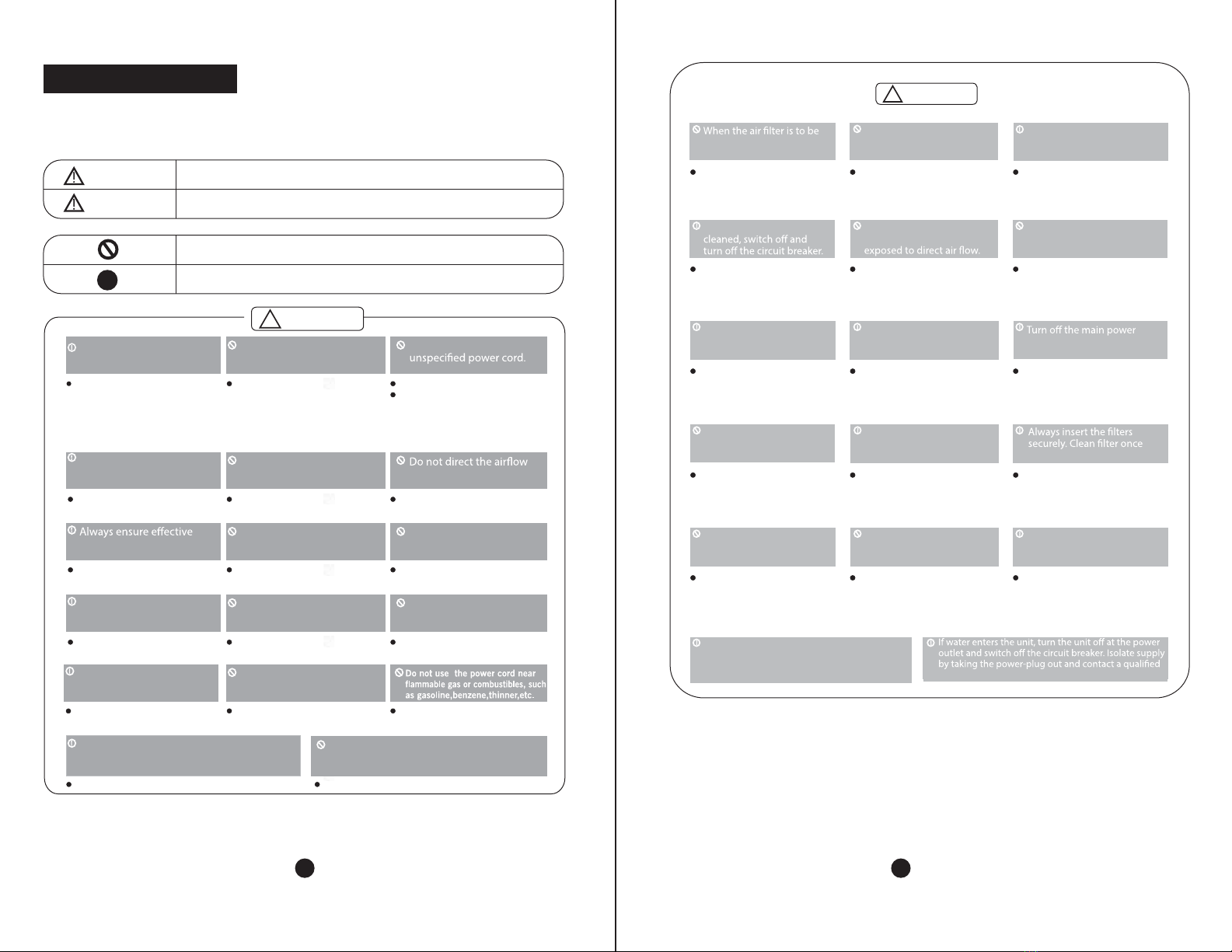
!
This symbol indicates the possibilty of death or serious injury.
This symbol indicates the possibilty of injury or damage to property.
WARNING
CAUTION
Never do this.
Always do this.
Plug in power cord
properly.
Do not operate or stop the
unit by inserting or pulling
out the power cord.
Do not damage or use an
It may cause electric shock or fire. If
the power cord is damaged, it may
be replaced by the manufacturer or
an authorized service center or a
similar qualified person in order to
avoid a hazard.
It may cause electric shock or fire
due to heat generation.
Otherwise, it may cause electric
shock or fire due to excess heat
generation.
Do not modify power cord
length or share the outlet
with other appliances.
Do not operate with wet
hands or in damp
environment. at room occupants only.
This could damage your health.
Always install circuit
breaker and a dedicated
power circuit.
Incorrect installation may cause fire
and electric shock.
Do not allow water to run
into electric parts.earthing.
It may cause electric shock or
fire due to heat generation.
Incorrect earthing may cause
electric shock.
Unplug the unit if strange
sounds, smell, or smoke
comes from it.
It may cause fire and electric
shock.
It may cause fire and electric
shock.
It may cause fire and electric
shock.
Leave the door closed
while the air conditioner
is running.
It is not designed to cool the entire
house.
Ventilate room before operating air
conditioner if there is a gas leakage from
another appliance.
It may cause explosion, fire and burns.
It may cause fire and electric
shock.
Do not disassemble or modify unit.
It may cause failure and electric shock.
It may cause an explosion or fire.
Do not use the power cord
close to heating appliances.
Do not open the unit
during operation.
Do not use the socket if it
is loose or damaged.
!
CAUTION
!
!
!
!
!
!
!
!
!
!
removed, do not touch the
metal parts of the unit.
Do not clean the air
conditioner with water.
Ventilate the room well when
used together with a stove,
etc.
It may cause an injury. Water may enter the unit and
degrade the insulation. It may
cause an electric shock.
An oxygen shortage may occur.
Do not use for special
purposes.
Do not put a pet or house
plant where it will be
When the unit is to be
Do not clean unit when
power is on as it may cause
fire and electric shock. It may
also cause an injury.
This could injure the pet or
plant.
Stop operation and close
the window in a storm or
hurricane.
Operation with windows
opened may cause wetting
of indoor and soaking of
household furniture.
Do not place obstacles
around air-inlets or inside
of air-outlet.
It may cause failure of
appliance or accident.
switch when not using the
unit for a long time.
Hold the plug by the head
of the power plug when
taking it out.
It may cause electric shock
and damage.
Ensure that the installation bracket
of the outdoor appliance is not
damaged due to prolonged exposure.
every two weeks.
It may cause failure of product
or fire.
Operation without filters may
cause failure.
If bracket is damaged, unit may
fall and get damaged.
Do not use strong deter-
gent such as wax or
thinner but use a soft cloth.
Do not place heavy objects on the
power cord and ensure that the
cord is not compressed.
There is danger of fire or
electric shock.
Appearance may be
deteriorated due to change of
product color or scratching of
its surface.
It contains contaminants and
could make you sick.
Do not drink water drained
from air conditioner.
Use caution when unpacking and
installing. Sharp edges could cause injury.
service technician.
Do not use this air conditioner to
preserve precision devices, food,
pets, plants, and art objects. It may
cause deterioration of quality, etc.
1 2

Usage
Cleaning and Maintenance
Service
Operating Temperature
1. Contact an installation specialist for installation.
2. Plug in the power plug properly.
3. Do not use a damaged or non-standard power cord.
4. Do not share the same outlet with other appliances.
5. Do not use an extension cord.
6. Do not start/stop operation by plugging/unplugging the power cord.
For repair and maintenance, contact your authorised service dealer.
Safety Precautions (prior to operation)
Cooling operation
Outdoor temp:
O
18-43 C
Indoor temp:
O
17-32 C
Preparing for operation
1. Exposure to direct airflow for an extended period of time could be hazardous to
your health. Do not expose occupants, pets, or plants to direct airflow for extended
periods of time.
2. Due to possibility of oxygen deficiency, ventilate the room when used together
with stoves or other heating devices.
3. Do not use this air conditioner for non-specificied special purposes (e.g. preserv-
ing precision devices, food, pets, plants, and art objects). Usage in such a manner
could harm such property.
1. Do not touch the metal parts of the unit when removing the filter. Injuries can occur
when handling sharp metal edges.
2. Do not use water to clean inside the air conditioner. Exposure to water can destroy
the insulation, leading to possible electric shock.
3. When cleaning the unit, first make sure that the power and circuit breaker are
turned off.
Note: Performance may be reduced outside of these operating temperatures.
1. Front panel
2. Air filter
3. Frame
4. Cabinet
5. Air inlet grille (outdoor side)
6. Air outlet grille
7. Electronic control keypad
8. Power supply cord
9. Remote control
UNIT PARTS IDENTIFICATION
POWER
CORD
A
E
N
E-Earth wire, yellow/green
N-Neutral wire, blue
A-Active wire, brown
Fig.1 Fig. 2
Wall outlet Air-break switch
Accessories
Seal
(Used on
drain joint)
1
1
Screw
Drain Joint Rubber Plug
NOTE
8
Wooden screw
(optional)
1. Power cord conductors are distinguished according to color as follows (see Fig.1)
2. For your safety and protection, this unit is earthed through the power cord (see Fig.2)
Please contact the manufacturer or its service agent or a similar qualified person if you
want to replace it.
3. Be sure that the unit being correctly grounded. The wall outlet (Air-break switch) should
be provided with reliable earth wire.
4. The unit should be provided with an individual circuit and the circuit breaker/fuse rating
should be the same as that of the power cord and wall outlet.
1 or 2
(depend on type you purchased)
2 (For >19000kJ/h models only:
used to fasten the front panel)
All the illustrations in the manual are for explanation purpose only. Your air conditioner may be
Remote for Remote model
3 4

Control Panel
AIR CONDITIONER FEATURES
Vent Control
The vent control is located above the control knobs. The operation method is different on
different models (see the following figures).
For maximum cooling efficiency, CLOSE the vent. This will allow internal air circulation.
OPEN the vent to discharge stale air.
CLOSE VENT OPEN
To open the vent, pull the lever toward you
To close it, push it in.
To open the vent, set the lever to the right position
To close it, set the lever in the left position.
CLOSE OPEN
NOTE: The VENTILATION LEVER should normally be kept in the CLOSED position during
cooling for maximum cooling effect. The "OPEN" position is used only for ventilation.
To adjust vertical air direction, adjust any one of the
horizontal louvre blades. When adjusting the horizontal louver
blades up or down, always keep the top or bottom blades
. This can e ctively prevent water droplets condensing
on the front panel of the unit.
horizontal
The air lter behind the inlet grille should be checked and
cleaned at least once every 2 weeks (or as necessary) to
maintain optimal performance of the air conditioner.
Vertical air flow adjustment (manually)
Air Filter
How to remove the air filter
1.
2.
3. Clean the lter with warm, soapy water. The water
should be below 40 C to prevent distortion of the lter.
4. Rinse o and gently shake o excess water from the
ter. Allow the lter to dry before replacing it. To prevent
distortion of the lter, do not dry in direct sunlight.
Hold the slot under the front panel, then uplift it outwards,
and remove the front panel.
Pinch the handle under the air lter and make the lter
arched, remove it from the slot from underside to upside.
O
See the following procedures to perform back drainage:
1. Fit the seal onto the drain joint (provided with your air
conditioner as accessory.)
2. Remove the rubber plug from the back of the unit
(if applicable) and insert it into the bottom drain hole.
3. Attach the drain joint tothe back of the cabinet where you
removed the plug and rotate it 90otosecurely assemble them.
4. Connect the drain joint with an extension drain hose
(locally purchased)
Note: If you choose non-drainage when cooling, both the bottom and the back drain holes of the unit
should be inserted with rubber plugs. When you choose non-drainage, the air conditioner will give
optimal cooling efficiency, but the unit may have a splashing sound due tothe blower wheel hitting the
accumulated water gathered in the base pan. The water then hits the condenser, and this results in a
higher cooling efficiency.
Drainage
SEAL
DRAIN
JOINT RUBBER
PLUG
5 6
POWER
SWING
SLEEP
HIGH
MED LOW
AUTO
COOL
DRY FAN
TIME R
SWING
FAN MODE
TIME ON
O
TIME OFF
TEMP
C

Use the remote controller within a distance of 5
meters from the appliance, pointing it towards
the receiver. Reception is confirmed by a beep.
Location of the remote controller.
5m
CAUTIONS
The air conditioner will not operate if curtains, doors or other materials block the signals
from the remote controller to the unit.
Prevent any liquid from falling into the remote controller. Do not expose the remote
controller to direct sunlight or heat.
If the infrared signal receiver on the indoor unit is exposed to direct sunlight, the air
conditioner may not function properly. Use curtains to prevent direct sunlight on the
receiver.
If other electrical appliances react to the remote controller, either move these
appliances or consult your local dealer.
HANDLING THE REMOTE CONTROLLER
Installation instructions of battery
Step 1: Insertacoin vertically in the groove
on the battery cover, clockwise rotation of 45
degrees, make sure that the groove is aligned
with the "unlock" sign
and remove the battery cover.
as shown below
Step 2: Install battery inside the remote
controller, the positive (+) side up.
Step 3: Install the battery cover, make
sure the battery cover groove
nsertacoin
vertically in the groove and press it
gently, then counter clockwise rotation
of 45 degrees, make sure the groove is
is aligned
with the "unlock" sign. I
aligned with the "lock" sign as shown
below.
Coin
Battery cover
Groove
Lock sign
Unlock sign
Groove
Unlock sign
Battery cover
Battery Positive (+) side up
Coin Groove
Battery cover
Unlock sign
Lock sign Coin
Groove
Battery cover
Unlock sign
Lock sign
Lock sign
Coin
WARNING
1. Battery must be disposed of properly. Do not
short circuit or dispose of in the fire.
2. Keep batteries out of the reach of children.
3. Caution for ingestion.
4. Non-rechargeable batteries are not to be
recharged.
5. Exhausted batteries are to be removed from
the product.
7 8

Model
Lowest Voltage of
CPU Emitting Signal
Rated Voltage
-5 C 60 C
5m
3.0V
2.4V
( Dry batteries Lr03x2)
~
Remote Contoller Specifications
Environment
Signal Receiving Range
NOTE:
-Buttons design is based on typical model and might be slightly different
from the actual one you purchased, the actual shape shall prevail.
-All the functions described are accomplished by the unit, if the unit has
no this feature, there is no corresponding operation happened when
press the relative button on the remote controller.
-When there are wide differences between Remote controller Illustration
and USERS MANUAL on function description, the description on USERS
MANUAL shall prevail.
RG15A1(B)/E, RG15A2(B)/E,
RG15A1(B)/E RG15A2(B)/E
Function buttons
Push this button to
decrease the indoor
temperature setting.
Press this button to
activate the Sleep
mode. This function is
available on COOL,
or AUTO mode only
and maintain the most
comfortable temperature
for you while saving
energy.
Operation starts when this button is
pressed and stops when the button
is pressed again.
Used to select the
desired fan speed.
ON/OFF button
MODE button
Press this button to
select the desired
operation mode.
TEMP DOWN button
TEMP UP button
FAN button
TIMER button
Push this button to
activate the uto
Start or uto Stop
program.
"A
" "A "
SLEEP button
SWING button
Push this button to
increase the temper-
ature setting.
Upon pushing SWING button,
the vertical louvres will
swing automatically from
side to side. Press it again
to deactivate the "SWING"
feature.(on some models)
910

Coolin/Fan operation
MODE
TEMP UP/DOWN
FAN
Ensure the unit is plugged in and power is
available.
1.
Press the button to select Cool or
Fan mode.
3. Press the button to set the
desired temperature.
4. Press the button to select the fan
speed.
Press the button to start the air
conditioner.
2.
ON/OFF
In Fan mode, the setting temperature is not
displayed in the remote controller and you are not
able to control the room temperature either. In this
case, only step 1, 2 and 4 may be performed.
NOTE
How to use the buttons
Auto operation
MODE
TEMP UP/DOWN
Ensure the unit is plugged in and power is
available.
1.
Press the button to select Auto.
3. Press the button to set
the desired temperature.
Press the button to start the air
conditioner.
2.
ON/OFF
3
4
2
1. In the Auto mode, the air conditioner can logically
choose the modes of Fan and Cooling
by sensing the e between the actual
ambient room temperature and the set temperature
on the remote controller.
2. You cannot change the fan speed in auto mode.
it has already been automatically controlled.
3. If the Auto mode is not comfortable for you , the
desired mode can be selected manually.
NOTE
1
3
3
2
1
3
3
2
1
3
2
1
2
Dehumidifying operation
Ensure the unit is plugged in andpower is
available.
1. Press the ON/OFFbutton to start the air
conditioner.
2. Press the MODEbutton to select Dry.
3. Press the TEMPUP/DOWN button to
set the desired temperature.
NOTE
In the Dehumidifying mode, you cannot change the
fan speed. It has already been automatically
controlled.
Timer operation
Press the Timer button to set the Auto-Start
and Auto-stop time of the unit. Auto-start/ Auto-stop
programs can be set from 0-12 hours.
NOTE:
To set Auto-start time, the unit must be in the
position.
To set Auto-stop time, the unit must be in the
On postion.
To set the Auto-start/stop time.
1. Press the TIMER button, when the TIMER
ON indicator displayed on the LED window
of the air conditioner, it indicates the Auto
Start setting program is initiated. When the
TIMER OFF indicator displayed on the LED
window of the air conditioner, it indicates the
Auto Stop setting program is initiated.
2. Press or hold the Up( ) or Down( ) to
change the Auto time. The control will count
down the time remaining until start/stop.
11 12

3. The selected time will register in 5 seconds
and the air conditioner will automatically
revert back to display the previous temper-
ature setting.
4. Turning the unit ON or OFF at any time
will cancel the Auto Start/stop function.
To cancel the TIMER setting, push
the TIMER button and press or hold the Up
( ) or Down( ) until 0 hour is displayed
on the LCD window of the air conditioner.
NOTE:
1
Swing operation
Use the SWING button to adjust the Left/Right
airflow direction.
1. Pressing this button while the unit is operational
will make the vertical louvers automatically swing
right and left, sweeping the cold/hot air alternately
to obtain comfortable cooling/heating.
2. Press the SWING button again to stop the
swing operation.
Over 50cm
FENCE
AWNING
75-150cm
Over 50cm
O
About 3~4
FENCE
AWNING
75-150cm
CAUTION
O
About 3~4
Preferred method of installation into a timber
framed wall, partition or window.
FLASH OR SEAL AROUND EXTERNAL
WALL FRAME OR ARCHITRAVE
STURDY TIMBER
FRAME ALL ROUND
UNIT
TIMBER FRAMED
WALL OR PARTITION
EXTERNAL SUPPORT
FRAME AT BALANCE
POINT OF A/C
ALTERNATIVELY, BRACKETS
AS ILLUSTRATED BELOW
MAY BE USED.
DRAIN PAN
Step 1
Remove the air conditioner from its packaging,
remove fixing screws and slide the air conditioner
out from the housing. (Refer toInstallation Steps).
Step 2
Prepare the hole in the wall sothat the bottom of the
housing is well supported, the top has minimum
clearance and the air inlet louvers have clearance
as shown below in options A and B. Holes from the
outside through tothe cavity should be sealed. The
housing should slope down towards the rear by
about 5mm to allow water formed during operation
to drain.
Step 3
Install the housing into the wall and ensure the foam
seals are not damaged. Seal or fill the gaps around
the inside and outside to provide satisfactory
appearance and protection against the weather,
insects and rodents.
Note: Unit may be supported by a
solid frame from below or by a
hanger from a solid overhead
support.
INSTALLATION INSTRUCTIONS
Select the Best Location
1. To avoid vibration and noise, make sure the units is installed securely and firmly.
2. Install the unit where the sunlight does not shine directly on it.
If the unit receives direct sunlight, build an awning toshade the cabinet.
3. There should be no obstacle, such as afence or wall within 50 cmfrom the back
of the cabinet because it will prevent heat radiation on the condenser. Restriction
of outside air will greatly reduce the cooling efficiency of the air conditioner.
4. Install the unit a little obliquely outward sothe codensed water will not leak into
the room (about 3~4° with level).
5. Install the unit with its bottom portion 75~150 cm above the floor level.
6. The power cord must be connected to an independent circuit. The yellow/green
wire must be grounded.
All side louvers of the cabinet must remain exposed to the outside of the structure.
Installation of the Housing
13 14

W
Alternative method of installation if external
support cannot be provided.
FLASH OR SEAL AROUND EXTERNAL
WALL FRAME OR ARCHITRAVE
STURDY TIMBER
FRAME
TIMBER FRAMED
ALL OR PARTITION
SOLID TIMBER SUPPORT
STEADYING BRACKET
(ONE PER SIDE)
DRAIN PAN
ENSURE LOUVRES
ARE ENTIRELY
OUTSIDE THE WALL
Step 1
Slide the unit into the housing until it is firmly against the
rear of the housing. Care is required to ensure the foam
sealing strips on the housing remain in position.
Step 2
Connect the air conditioner to the power and position the
excess cord length beneath the air conditioner base.
Step 3
Engage the chassis fixing brackets into the bottom housing
rail and secure to the base with the screw
provided.
Step 4
Remove the front panel from it’s carton and plastic bag and
fit as per the Installation Instruction.
Step 5
Switch unit on. Check for operation of the unit and check for
vibration in the installation.
Step 6
Fit the drain pan to the housing and run a drain line to a
suitable location if required.
AIR IN
AIR IN
AIR OUT
100mm minimum
OPTION A
AIR IN
LOUVRE
BRICK
WALL
O
45 BRICK CUT AWAY
TO CLEAR LOUVRES
FRONT
AIR OUT
AIR INAIR IN
TOP
VIEW
O
45 BRICK CUT AWAY
TO CLEAR LOUVRES
100mm
BRICK
WALL
100mm
OPTION B
Installations of the unit into the wall
Installations of the unit into the housing
Step 4. Install the frame
Fix the screws on the frame (See Fig.3).
Step 5. Install the air filter and front panel
a. Install the air filter into the frame’s slot from upside to underside
(See Fig.2).
b. Hang the front panel on the frame’s buckle, then press the front
panel into the frame’s slot until you hear a click (See Fig.10).
6
45
Installations steps
Step 1. Remove the front panel and the air filter
a. Hold the slot under the front panel, then uplift it outwards, and remove the front panel (See Fig.1).
b. Pinch the handle under the air filter and make the air filter arched, remove it from the slot from
underside to upside (See Fig.2).
Step 2. Remove the frame
a. Remove the two fixing screws from the frame (See Fig.3).
b. Grasp the left corner of the frame’s underside, release the coupler plugs, then loosen the frame
(See Fig.4).
Step 3. Installation
a. Remove the two fixing screws on the chassis fixing brackets, then remove the chassis fixing brackets
(See Fig.5).
b. Grasp the handle on the chassis and carefully slide the air conditioner out of the cabinet (See Fig.6).
c. Remove shipping pad from around compressor before operation and make sure the discharge points
to the
15 16

17
Clean your air conditioner occasionally to keep it looking new. Be sure to unplug
CAUTION
Air Filter Cleaning
The air filter should be checked at least once a
month to see if cleaning is necessary. Trapped
particles in the filter can build up and cause an
accumulation of frost on the cooling coils.
CARE AND CLEANING
Cabinet Cleaning
Hold the slot under the front panel, then uplift it onwards, and remove the front panel.
Pinch the handle under the air filter and make the air filter
arched, remove it from the underside to upside.
Wash the filter using liquid dishwashing detergent and warm
water. rinse filter thoroughly.
Gently shake excess water from the filter. Be sure the filter
is thoroughly dry before putting it back.
Or, instead of washing you may vacuum the filter to clean.
Note: Never use hot water over 40°C (104°F) to clean the
air filter. Never attempt to operate the unit without the air filter.
Be sure to unplug the air conditioner to prevent shock or fire hazard. The cabinet and
front panel may be dusted with an oil-free cloth or washed with a cloth dampened in a
solution of warm water and mild liquid dishwashing detergent. Rinse thoroughly and
wipe to dry.
Never use harsh cleaners, wax or polish on the cabinet and front panel.
Be sure to wring excess water from the cloth before wiping around the controls.
Excess water in or around the controls may cause damage to the air conditioner.
Plug in air conditioner.
Note: Never use water over 50°C, alcohol, gasoline, acid, solvent or brush to clean the
18
Other manuals for RG15A1/E
1
This manual suits for next models
5
Table of contents
Other Midea Inverter manuals

Midea
Midea M2OC-14HRDN1 Operating manual

Midea
Midea MOU-12HDN1 User manual

Midea
Midea MVUR252B-VA3 User manual

Midea
Midea MDV-V120W/DRN1 Operating manual

Midea
Midea Super DC Series User manual

Midea
Midea MSMABU-09HRDN8-QRD0GW User manual

Midea
Midea 11DSNA-A-1301 User manual

Midea
Midea IC SI-A-1205 User manual

Midea
Midea MDV-120W/DON1 Operating manual

Midea
Midea MSAEAU-09HRFN1-QRD0GW User manual