Preference K-602 User manual
The Architectural Loudspeaker:
INSTALLATION GUIDE
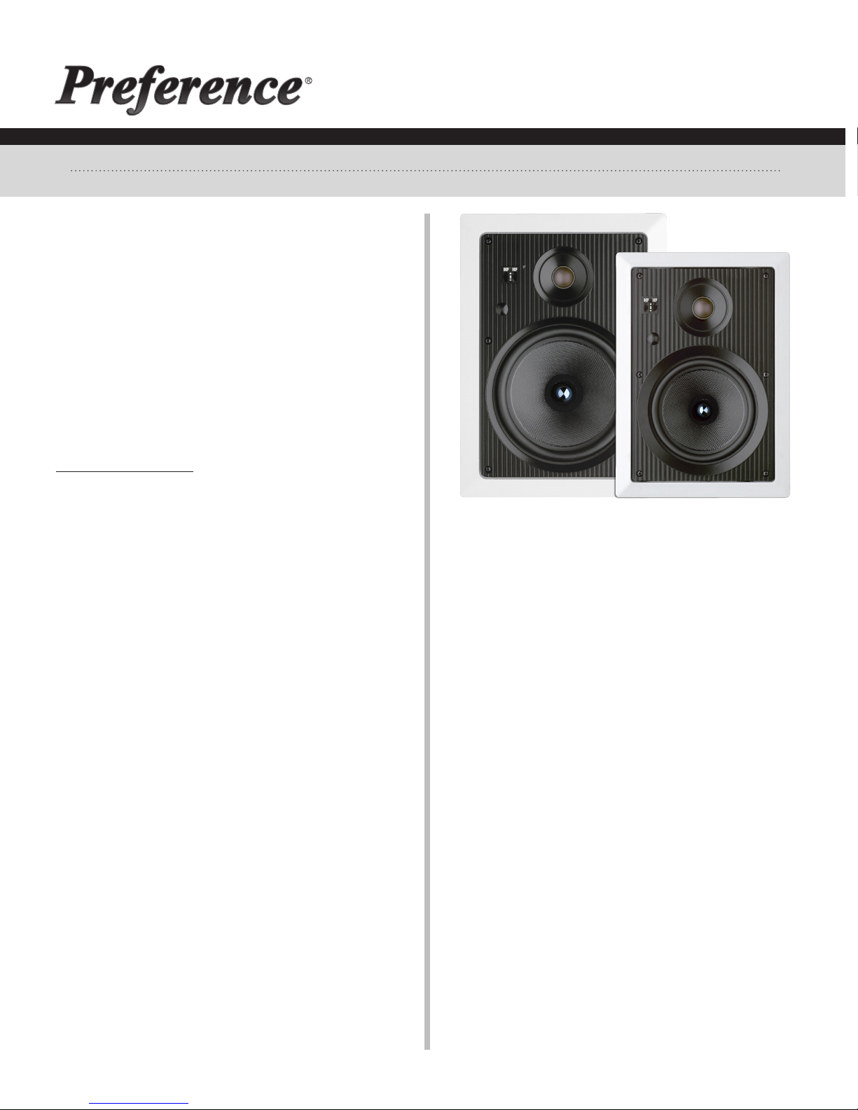
For 6-1/2" & 8" In-Wall Models
Overall Cut-Out (Round x Depth)
K-602 6-1/2"In-WallLoudspeaker 2-PieceBafe&Frame 9-1/16"x12-3/4" 8"x11-3/4"x3-1/4"
K-802 8"In-WallLoudspeaker 2-PieceBafe&Frame10-1/2"x14-1/2" 9"x13"x3-1/4"
In-Wall models
Congratulations! You have purchased a high quality stereo
loudspeaker. When matched to comparable electronic
equipment, expect years of quality high delity sound. We
are constantly striving to provide the very best technology
has to offer.
The following manual is designed to give you, the installer
or owner, basic information as to the speaker’s installation
and operation. It is beyond the scope of this manual to go
into all the details that must be taken into consideration in
a sophisticated high delity system.
If you have any questions regarding this speaker which are
not answered by this manual, contact your local dealer for
assistance. For the most current information please visit
www.oemsystems.com.
GENERAL DESCRIPTION
These two-way speakers have specially designed woofers
with linear long throw butyl rubber surrounds for long life
and superior damping. Dome tweeters are utilized for
excellent high frequency dispersion throughout your entire
listening environment. Two piece bafe/frame assemblies
allow for custom painting of the frames and grilles without
the need to mask the speakers.
SHIPPING DAMAGE
Each speaker is thoroughly tested before it leaves the
factory. However, in shipment, accidents may occur.
Please inspect your speakers carefully when you receive
them to make sure there is no damage. If there is, please
notify your dealer, or supplier immediately for assistance.
If you received your speakers by public transportation,
report the damage at once to the shipping company.
AMPLIFIER OPERATION
These speakers will perform well with ampliers from 5
to 125 Watts RMS. However, damage to the speakers can
be done by ampliers of nearly any power rating if the
amplier is overdriven into clipping. “Amplier clipping”
is a phrase used to describe a condition when, because of
the volume demand, an amplier is being asked for more
power than it can give. Clipping causes distortion of the
audio signal. If you should hear an unusual amount of
distortion at high listening levels then consider reducing
the volume. DAMAGE DONE TO A SPEAKER BY CLIPPING IS
NOT COVERED UNDER THE WARRANTY.
SPEAKER PLACEMENT
Placement of Wall Mounted Speakers should be carefully
considered. Ideally, the speakers should be located
where they will provide the best possible sound and ease
of installation. It is beyond the scope of this publication to
discuss all of the various aspects of speaker placement.
Please contact a professional for assistance if you are
uncomfortable with the planning or installation process.
Note: Though these speakers are referred to as “wall
mount,” they are also suitable for installations in ceilings
and custom cabinetry.
WIRING
To achieve maximum performance from your new speakers
we strongly suggest the use of good quality stereo cable.
There are many good brands available. We recommend
that the cable be at least 16 gauge or larger for runs of
over 50 feet and that the wire be double insulated. This is
often referred to as “jacketed” speaker cable. “Zip cord,”
which is single insulated and is often made with clear
insulation, should be avoided as it is not as durable. It is
important when installing the wiring and speakers that
you adhere to all local codes and regulations. We suggest
that a professional be consulted in order to maximize your
system’s performance. The following, however, are some
useful suggestions.
Try to keep the wire length to a minimum. However, allow
about 2½ feet of free wire at the speaker cut-out and
sufcient length at the electronics to aid in the ease of
installation. Adding extra wire later is tedious and time
consuming.
Avoid bundling speaker cables parallel to electrical cables
K-802 K-602
page 1 of 2Rev. A
for extended lengths. Though the impedance is
low and the likelihood of interference low, this
may help reduce hum and RF interference. When
securing the wire, use care not to staple or nail
the electrical conductors. Doing so could result
in a short that might damage the electronics.
More than two pair of these speakers can
be connected to one amplier. However, we
suggest that you consult a professional if you are
installing more than two pair.
When connecting your speakers, make sure
proper polarity (phasing) is maintained. Simply
put, this means being sure the same wire which
is hooked to the positive terminal of the amplier
has its other end hooked to the positive terminal
of the speaker. It is important to check this on
all speakers. If the connections on one of the
speakers are reversed, (out of phase) the quality
of your bass will be seriously impaired.
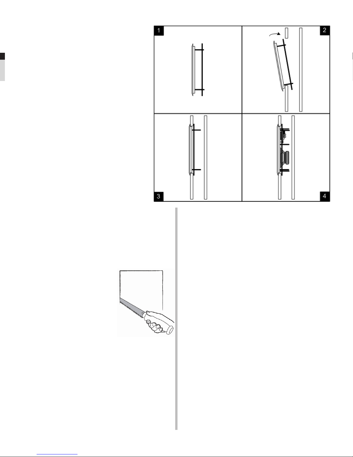
INSTALLATION
As the diagrams show, the speakers utilizes a
metal mounting ring which, after tightening with
the screws provided, acts as a clamp to hold the
speakers in place.
To aid in speaker performance, a brous material, such
as berglass or polyester ber, may be placed behind the
speaker. This may also help to reduce unwanted sound
from being transmitted into adjoining rooms.
Once you determine where you wish the speakers to be
placed, do the following:
Using the paper template provided,
mark the speaker cut-out location
making sure that where you wish
the speakers to be placed will not be
obstructed by a stud or other material
hidden in the wall. Proper use of an
electronic stud-nder is invaluable
for this operation. Using the proper
equipment, cut the appropriate
sized hole in the wall. On drywall,
the cleanest cuts will be made with a
drywall saw.
Install the frame and mounting ring assembly by passing
the black mounting ring through the cut-out as illustrated.
(see gures 1 and 2) For the 8” speakers, observe that
there is a top and bottom to the frame. The top and
bottom are identiable by the spacing between the six
vacant screw holes in the black clamp ring. The more-
closely spaced holes are toward the top. Next, verify that
the speaker frame ts into the cut-out. The white frame
should t snugly and smoothly in the cut-out hole. If the
hole should have been cut a little too large, the ange on
the frame should cover this.
Once the frame is in place, gently tighten all of the screws
so that the mounting ring is up against the back side of the
wall board. (see g. 3) Avoid over-tightening the screws or
it may later become difcult to install the grille.
If the wire has not yet been run, do so, now that you have
access to the wall’s interior. Once the speaker wire has
been run, pull the end of the wire out of the wall, strip back
a section of the jacket as needed, and then expose ½" of
each conductor. Connect the wire to the terminals on the
back of the speaker assembly, observing polarity (+ & -).
Insert the speaker into the frame and install the six screws.
Tighten the screws starting with the middle pair of screws
followed by the top pair and then the bottom pair. (see
g. 4) Use care not to over-tighten the screws or it may
later become difcult to install the grille. Install the grilles
after testing the operation of the speakers. The grilles are
installed by gently working the edge of the grille into the
frame of the speaker, beginning at one corner and working
one or both directions around to an adjacent or opposite
corner.
preference-audio.com
info@preference-audio.com
page 2 of 2Rev. A
This manual suits for next models
1
Table of contents
Other Preference Speakers manuals


