Preference K-5LCRSd User manual

page 1 of 2Rev. B
The Architectural Loudspeaker:
INSTALLATION GUIDE
For 5-1/4" LCR In-Wall Models
Overall Cut-Out (Round x Depth)
K-5LCRSd Dual5-1/4"LCRIn-WallLoudspeakerFramelessBafe&Grille9"x15-3/4"7-15/16"x14-7/16"x3-1/4"
In-Wall models
K-5LCRSd
Congratulations! You have purchased a high quality stereo
loudspeaker. When matched to comparable electronic equipment,
expect years of quality high delity sound. Our belief is that music
matters and we are focused on delivering superlative music
reproduction everywhere in your home.
The following manual is designed to give you, the installer or
owner, basic information as to the speaker’s installation and
operation. It is beyond the scope of this manual to go into all the
details that must be taken into consideration in a sophisticated
high delity system. When installing the wiring and speakers it is
important to adhere to all local codes and regulations. Consulting
a professional will help to maximize your system’s performance.
If you have any questions that are not answered by this manual,
contact your local dealer for assistance. For the most current
information please visit: www.preference-audio.com.
GENERAL DESCRIPTION
These two-way speakers have specially designed woofers with
linear long throw butyl rubber surrounds for long life and superior
damping. Pivoting Dome Tweeters are utilized for excellent
high frequency dispersion throughout your entire listening
environment.
SHIPPING DAMAGE
Each speaker is thoroughly tested before it leaves the factory.
However, in shipment, accidents may occur. Please inspect your
speakers carefully when you receive them to make sure there
is no damage. If there is, please notify your dealer, or supplier
immediately for assistance. If you received your speakers by
public transportation, report the damage at once to the shipping
company.
AMPLIFIER OPERATION
These speakers will perform well with ampliers from 5 to 125
Watts RMS. However, damage to the speakers can be done by
ampliers of nearly any power rating if the amplier is overdriven
into clipping. “Amplier clipping” is a phrase used to describe
a condition when, because of the volume demand, an amplier
is being asked for more power than it can give. Clipping causes
distortion of the audio signal. If you should hear an unusual
amount of distortion at high listening levels then consider
reducing the volume. DAMAGE DONE TO A SPEAKER BY CLIPPING
IS NOT COVERED UNDER THE WARRANTY.
SPEAKER PLACEMENT
Placement of In-wall Speakers should be carefully considered.
Please contact a professional for assistance if you are
uncomfortable with the planning or installation process.
Ideally, the speakers should be located where they will provide
the best possible sound and ease of installation. It is beyond the
scope of this publication to discuss all of the various aspects of
speaker placement but here are some helpful suggestions.
For more bass, place the speakers between 18 and 36 inches
from an adjacent wall as measured to the center of the speaker.
Avoid placing the speakers less then 18 inches from an adjacent
wall. When placing speakers near a corner, avoid locating them an
equal distance from the two adjacent srfaces.
When used in a home theater the front left and right speakers
should be separated from each other a distance of 0.8 to 1.2
times the seating distance (assuming they are on the same
plane as the center speaker). For example, if the seating position
is 10 feet from the viewing screen and/or center speaker then
ideally the distance between the left and right speakers should
be somewhere between 8 and 12 feet, (10 x 1.2ft = 12ft). MTM
style speakers are best installed in portrait orientation. However,
landscape is often used for the center speaker for aesthetic
or clearance purposes. If the speakers are located behind an
acoustically transparent screen then all the speakers should
be oriented portrait style. Tweeters may be aimed toward the
listening area by pressing the lens area along side the tweeter
dome.
WIRING
To achieve maximum performance we recommend that the
speaker cable be at least 16 gauge or larger for runs over 50 feet
(15m) and that the cable be double insulated. A CL-2 or CL-3 rated
cable may be required. Check local codes. “Zip cord,” which is
single insulated and is often made with clear insulation, should be
avoided as it is not as durable. Allow about 2½ feet (0.8m) of free
cable at the speaker cut-out and sufcient length at the other end
to reach the electronics. Having to add extra cable later can be
tedious and time consuming.
Avoid bundling speaker cables parallel to electrical cables for
extended lengths. Though the impedance is low and the likelihood
of interference low, this may help reduce hum and RF interference.
page 2 of 2Rev. B
When securing the cable, use care not
to staple or nail through the electrical
conductors. Doing so could result
in a short that might damage the
electronics.
When connecting your speakers,
make sure proper polarity (phasing) is
maintained. Simply put, this means
ensuring the same wire which is connected to the positive
terminal of the amplier has its other end connected to the
positive terminal of the speaker. It is important to check this on all
speakers. If the connections on one of the speakers are reversed,
(out of phase) the sound quality will be impaired.
INSTALLATION
If the drywall has not yet been installed a Rough-in-Bracket (RIB-
LCR) may be used to reserve the speaker location on the wall.
The RIB-LCR brackets are available from the distributor or dealer
where the speakers were purchased. When these brackets are
used the holes are cut when the drywall is installed. The cable can
be tied off on the bracket after securing the cable to a nearby joist.
If the drywall is installed and the speaker locations have not yet
been established, then do so now. Assess the wall for possible
concealed obstructions such as wiring, plumbing, etc. Inspect the
backside of the wall, the attic, and/or the crawl space if available
for clues to possible obstructions. Use inspection holes with
inspection tools (camera, mirror, ashlight, etc.) if absolutely
necessary. Use a “stud nder” to locate the positions of the studs.
The K-5LCRSd is shipped with a horizontal Retro
Ring and a vertical retro ring . With retro
ring , the edge of the speaker opening must be
at least 1/2" (13mm)
away from a stud if the
speaker is installed in
the portrait orientation.
Retro ring is for
mounting closer to the
stud when in the portrait
orientation.
Once the speaker locations are established
use the cardboard template (the outside
of the inner cardboard rectangle) to mark
the speaker cut-out. The dimensions for
the cut-out are listed on the previous page.
Using the proper tool, cut the appropriate
sized hole in the wall. On drywall, clean
cuts can be made with a drywall saw.
If the cable has not yet been run, do so once you have access to
the wall’s interior.
To aid in speaker performance, a brous material, such as
berglass, may be placed behind the speaker. This may also help
to reduce unwanted sound from being transmitted into adjoining
rooms. If the wall space has blown or loose insulation, care must
be taken to prevent the loose insulation from entering the back
of the speaker. This can be accomplished by placing a batt of
berglass insulation over the back of the speaker.
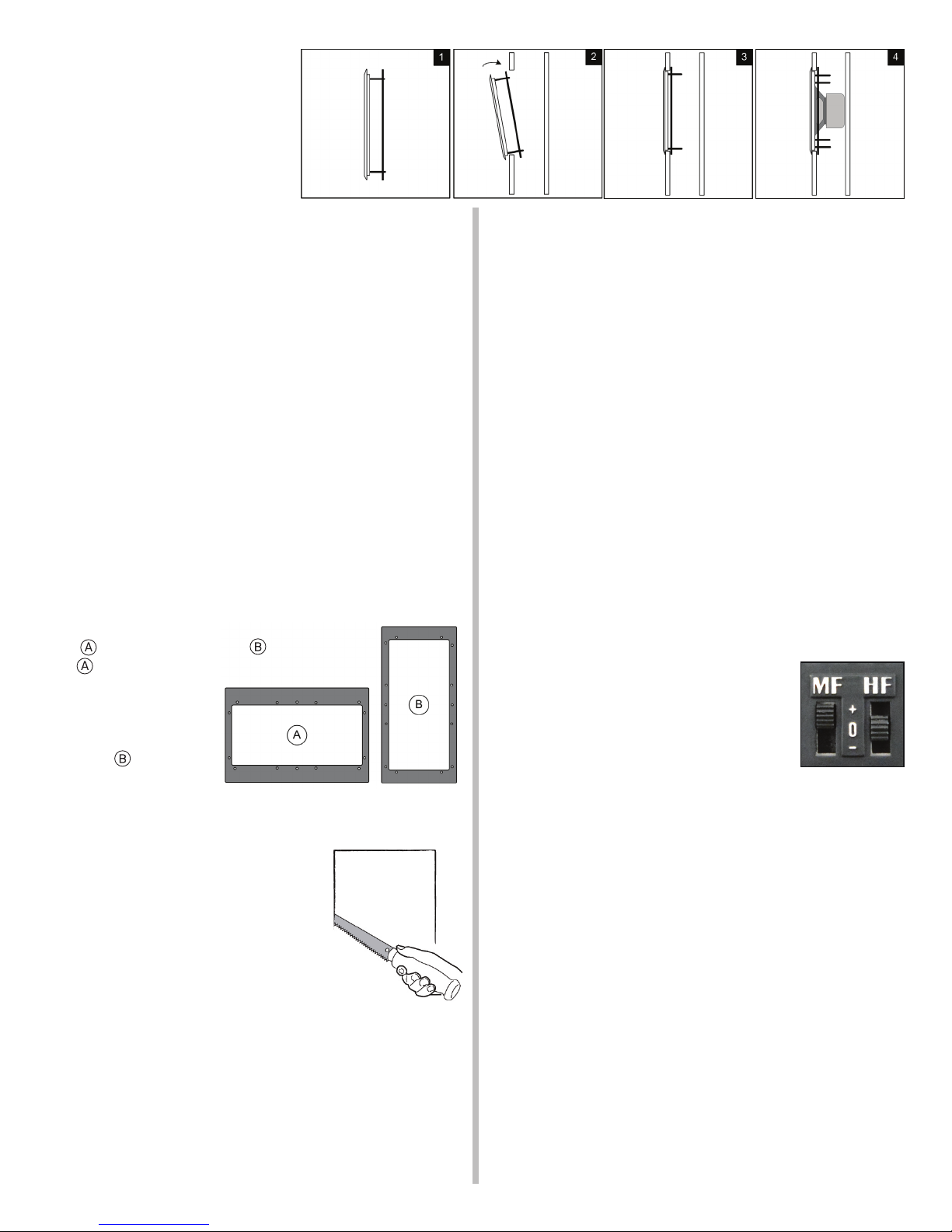
As the diagrams above show, the speakers utilize a metal Retro
Ring which, after tightening the 4 provided screws, acts as a clamp
to hold the magnet frame in place. Note: Use only the 4 outer
holes for mounting the frame.
Install the frame and retro ring assembly by passing the metal
retro ring through the cut-out as illustrated in gures 1 & 2. The
magnet frame should t cleanly, without interference, in the cut-
out hole. If the hole is a little small then trim the hole as needed.
Lightly tighten the screws to secure the retro ring against the back
of the wall (see g. 3). Use care not to over-tighten the screws or
the frame may become distorted.
Pull the end of the cable out of the wall, strip back a section of the
jacket as needed, and then expose ½" (13mm) of each conductor.
Connect the wire to the terminals on the back of the speaker
assembly, observing polarity (+ & -).
Insert the speaker into the frame and install the eight screws
(see g. 4).
The mid and high frequency levels can also be
adjusted as desired using the mid frequency
(MF) and high frequency (HF) switches. The MF
switch changes the output level in the lower
midrange. Increasing the level adds more body
to the midrange, while decreasing it creates a
lighter presentation. Decreasing the level may
benet the sound reproduction when the speaker is mounted
close to another surface.
The HF switch changes the output level of the upper midrange
and high frequencies. Increasing the level creates a brighter
presentation while decreasing it produces a softer one.
The grilles can be painted using multiple light coats of spray paint.
Custom color spray paints are available from specialty companies.
Contact your dealer for more information. The grilles should be
removed from the speaker and painted in a clean environment to
prevent contamination. It is best to go around the grilles and apply
the paint from multiple angles. DO NOT remove the scrim cloth
from the backside of the grille. It is not replaceable.
Attach the grilles to the speakers and enjoy. Should you wish
to remove the grilles from the speakers pull at the grilles' edge.
Initially there will be signicant resistance because the grilles are
magnetically attached.
preference-audio.com
info@preference-audio.com
Table of contents
Other Preference Speakers manuals


Popular Speakers manuals by other brands


Advanced Visual Solutions
Advanced Visual Solutions CSGAMKIT01 Installation and operating instructions

Dynasty ProAudio
Dynasty ProAudio WSA-5RP-PLUS manual

Bang & Olufsen
Bang & Olufsen BEOLAB 28 user manual

Conquer
Conquer CQL1572-B instruction manual

Opvimus
Opvimus BS-20BA instruction manual

Boss Audio Systems
Boss Audio Systems MPWT50RGB user manual