Preference K-W6LCRSd User manual

page 1 of 4Rev. Apage 4 of 4Rev. A
INSTALLATION GUIDE
Overall Cut-Out (Round x Depth)
K-W6LCRSd 6-1/2"In-WallLCRLoudspeakerwithRotatingWaveguide 9"x15-3/4" 7-15/16"x14-7/16"x3-1/2"
You have purchased a high quality stereo
loudspeaker. When matched to comparable electronic
equipment, expect years of quality high delity sound. Our
belief is that music matters and we are focused on delivering
superlative music reproduction everywhere in your home.
The following manual is designed to give you, the installer or
owner, basic information as to the speaker’s installation and
operation. It is beyond the scope of this manual to go into all the
details that must be taken into consideration in a sophisticated
high delity system. When installing the wiring and speakers it is
important to adhere to all local codes and regulations. Consulting
a professional will help to maximize your system’s performance.
If you have any questions that are not answered by this manual,
contact your local dealer for assistance. For the most current
information please visit: www.preference-audio.com.
Each speaker is thoroughly tested before it leaves the factory.
However, in shipment, accidents may occur. Please inspect your
speakers carefully when you receive them to make sure there
is no damage. If there is, please notify your dealer, or supplier
immediately for assistance. If you received your speakers by
public transportation, report the damage at once to the shipping
company.
These speakers will perform well with ampliers from 5 to 125
Watts RMS. However, damage to the speakers can be done by
ampliers of nearly any power rating if the amplier is overdriven
into clipping. “Amplier clipping” is a phrase used to describe
a condition when, because of the volume demand, an amplier
is being asked for more power than it can give. Clipping causes
distortion of the audio signal. If you should hear an unusual
amount of distortion at high listening levels then consider
reducing the volume. DAMAGE DONE TO A SPEAKER BY CLIPPING
IS NOT COVERED UNDER THE WARRANTY.
This speaker was designed and engineered to provide the nest
performance achievable in a compact package. The custom
waveguide is unique in the industry and provides cross-axis
performance that gives every listener in the room a sense of
envelopment unmatched by other speakers in this category.
By focusing the sound eld across the listening space, the
listener experiences a more balanced and symmetric sound level,
especially when the main speakers are spaced more closely than
is ideal, (common in many of today’s home theaters).
The waveguide also increases the efciency of the tweeter,
allowing it to operate with far less input power and signicantly
lowering the distortion. This also
allows for the elimination of the
ferro-uid used for heat dissipation,
improving elements of the tweeter’s
performance including part-to-part
consistency. This same waveguide
also allows the tweeter to operate a
full octave lower than conventional
dome tweeters while simultaneously
reaching more than a half octave
higher in frequency. This allows the
tweeter to cover more of the critical
voice range.
But we’re not done yet. This same
cross-axis tweeter design creates
a much smoother off-axis listening
experience, eliminating the midrange-
hole that is commonly experienced
with conventional designs. Additionally, by controlling the
directivity of the sound eld, the early reections that occur from
nearby walls and furniture are reduced so that more of the direct
sound from the speakers are heard, improving the intelligibility
and detail of the original sound source.
Finally, the inset tweeter produces a time aligned position and
excellent phase coherency with the woofer, improving the off-axis
performance, both in the vertical and horizontal directions.
While the tweeter has allowed us to create a truly unique speaker,
the woofer’s complement of components provides the balance of
performance. Every detail of the woofer was considered using a
“Design of Experiments” methodology:
• Cast aluminum basket with its stiff but inert structure
• Super-light extra-long copper-clad aluminum voice coil
• Low eddy-loss mechanically damped Kapton former
• Lightweight curved woven cone made from genuine Dupont Kevlar®
• Linear-transitioning butyl rubber surround
• Vibration damping silica rubber motor boot
• High compliance at spider
• Machined aluminum heat-dissipating phase plug
Clearly, care was exercised to create a woofer that behaves as well
off-axis as it does on-axis and meets the tweeter’s top caliber
performance.
Of course all of this performance is brought together using a
sophisticated multi-order crossover that seamlessly blends the
drivers for performance that rivals and exceeds everything in
its class. The crossover contains two level controls to tailor the
speaker for the application.
There are 2 switches located on the front bafe, labeled MF and
HF, (Mid-Frequency and High-Frequency, respectively). Each
switch has 3 positions that allow the user to tailor the sound of
the speaker for different room acoustics, mounting locations,
and personal preference. These controls are also useful when
using the speakers behind acoustically transparent video screens
(where some augmentation of the upper frequencies may be
necessary) or when customizing the speakers for unique surround
applications where the sound may be either focused directly at
the seating area or reected off nearby surfaces. The diagrams
below show an approximation of how each control affects the
frequency response. Moving the switches up (Toward +) increases
the output.
The Mid-Frequency (MF) control allows for a relaxed, neutral, or
forward midrange presence.
The High-Frequency (HF) control affects the uppermost audible
range to create soft, neutral, or articulate detail.
The grilles can be painted using multiple light coats of spray paint.
Custom color spray paints are available from specialty companies.
Contact your dealer for more information. The grilles should be
removed from the speaker and painted in a clean environment to
prevent contamination. It is best to go around the grilles and apply
the paint from multiple angles. DO NOT remove the scrim cloth
from the backside of the grille. It is not replaceable.
Attach the grilles to the speakers and enjoy. Should you wish
to remove the grilles from the speakers pull at the grilles' edge.
Initially there will be signicant resistance because the grilles are
magnetically attached.
www.preference-audio.com info@preference-audio.com
(775)355-0405 (800)291-0561FAX
K-W6LCRSd
- Front Channel
- Center Channel
- Side Channel
- Rear Channel
- Subwoofer
- 2 Channel Ambient
For more bass, place the speakers between 18 and 36 inches
from an adjacent wall as measured to the center of the speaker.
Avoid placing the speakers less then 18 inches from an adjacent
wall. When placing speakers near a corner, avoid locating them an
equal distance from the two adjacent srfaces.
When used in a home theater the front left and right speakers
should be separated from each other a distance of 0.8 to 1.2
times the seating distance (assuming they are on the same
plane as the center speaker). For example, if the seating position
is 10 feet from the viewing screen and/or center speaker then
ideally the distance between the left and right speakers should
be somewhere between 8 and 12 feet, (10 x 1.2ft = 12ft). If the
speakers are located behind an acoustically transparent screen
then all the speakers should be oriented portrait style. The
tweeter should be aimed toward the listening area.
To achieve maximum performance we recommend that the
speaker cable be at least 16 gauge or larger for runs over 50 feet
(15m) and that the cable be double insulated. A CL-2 or CL-3 rated
cable may be required. Check local codes. “Zip cord,” which is
single insulated and is often made with clear insulation, should be
avoided as it is not as durable. Allow about 2½ feet (0.8m) of free
cable at the speaker cut-out and sufcient length at the other end
to reach the electronics. Having to add extra cable later can be
tedious and time consuming.
Avoid bundling speaker cables parallel to electrical cables for
extended lengths. Though the impedance is low and the likelihood
of interference low, this may help reduce hum and RF interference.
When securing the cable, use care not to staple or nail through the
electrical conductors. Doing so could result in a short that might
damage the electronics.
When connecting your speakers, make sure proper polarity
(phasing) is maintained. Simply put, this means ensuring the
same wire which is connected to the positive terminal of the
amplier has its other end connected to the positive terminal of
the speaker. It is important to check this on all speakers. If the
connections on one of the speakers are reversed, (out of phase)
the sound quality will be impaired.
If the drywall has not yet been installed a Rough-in-Bracket (RIB-
LCR) may be used to reserve the speaker location on the wall.
The RIB-LCR brackets are available from the distributor or dealer
where the speakers were purchased. When these brackets are
used the holes are cut when the drywall is installed. The cable can
be tied off on the bracket after securing the cable to a nearby joist.
If the drywall is installed and the speaker locations have not yet
been established, then do so now. Assess the wall for possible
concealed obstructions such as wiring, plumbing, etc. Inspect the
backside of the wall, the attic, and/or the crawl space if available
for clues to possible obstructions. Use inspection holes with
inspection tools (camera, mirror, ashlight, etc.) if absolutely
necessary. Use a “stud nder” to locate the positions of the studs.
Once the speaker locations are
established use the cardboard template
(the outside of the inner cardboard
rectangle) to mark the speaker cut-
out. The dimensions for the cut-out
are listed in the chart on the previous
page. Using the proper tool, cut the
appropriate sized hole in the wall. On
drywall, clean cuts can be made with a
drywall saw.
If the cable has not yet been run, do so
now that you have access to the wall’s
interior.
To aid in speaker performance, a brous
material, such as berglass, may be
placed behind the speaker. This may
also help to reduce unwanted sound
from being transmitted into adjoining
rooms. If the wall space has blown or
loose insulation, care must be taken
to prevent the loose insulation from
entering the back of the speaker. This
can be accomplished by placing a batt
of berglass insulation over the back
of the speaker.
Install the frame and retro ring
assembly by passing the metal retro
ring through the cut-out as illustrated
in The
frame should t cleanly, without
interference, in the cut-out hole. If the
hole is a little small then trim the hole
as needed. Lightly tighten the screws
to secure the retro ring against the back
of the wall Use care not to
over-tighten the screws or the frame
may become distorted.
Pull the end of the cable out of the wall,
strip back a section of the jacket as
needed, and then expose ½" (13mm) of
each conductor. Connect the wire to the
terminals on the back of the speaker
assembly, observing polarity (+ & -).
Insert the speaker into the frame and
install the eight screws
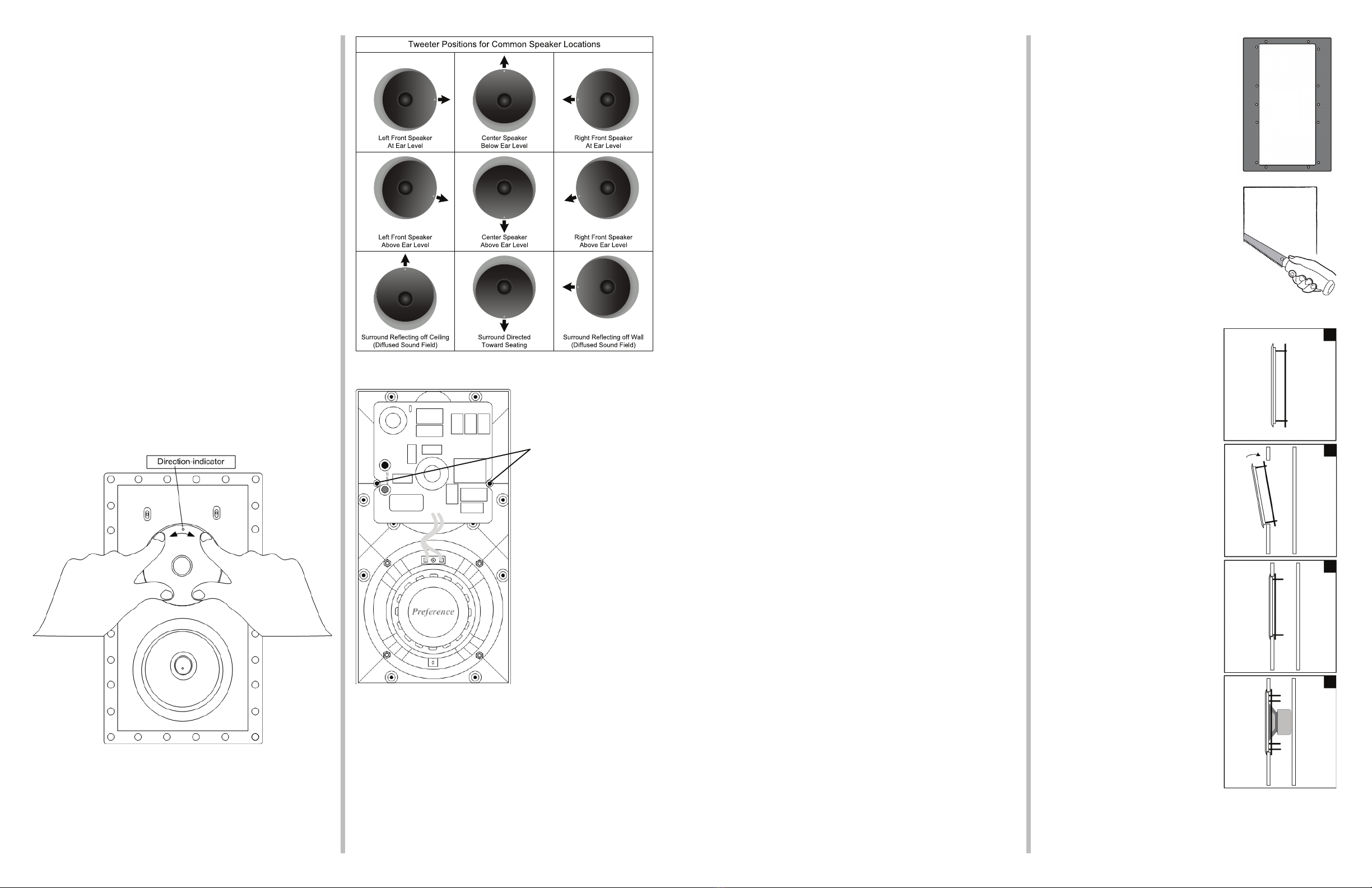
This speaker can be used for 2-channel High Resolution audio or
for nearly any speaker location within a home theater system. The
chart to the right provides suggested tweeter orientations for a
number of common speaker locations within a home theater. We
encourage you to experiment with the tweeter orientation to see
what works best within your system, especially with surround
placements.
While it may seem unconventional to use this speaker in the
Landscape orientation for the center dialog speaker, it is actually
well suited because of the excellent phase coherency between
the tweeter and woofer. The speaker actually outperforms most of
MTM (Mid-Tweeter-Mid) designs that have become commonplace
for the center dialog channel.
• The tweeter should be rotated into the desired position for
optimal performance.
• There are detents every 15 degrees. The tweeter will lock into
these detents when positioned over them.
• Press rmly at the edge of the tweeter waveguide using 4 ngers.
• A gap of about 2mm will appear at the edge when depressed.
• Rotate the tweeter into the desired position, releasing when you
feel a detent.
• NOTE: It may be necessary to moisten one's ngers to achieve
good traction on the waveguide.
• The detents will not be felt when the waveguide is fully
depressed. Decrease pressure to locate the detents.
Placement of In-wall speakers should be carefully considered.
Please contact a professional for assistance if you are
uncomfortable with the planning or installation process.
Ideally, the speakers should be located where they will provide
the best possible sound and ease of installation. It is beyond the
scope of this publication to discuss all of the various aspects of
speaker placement but here are some helpful suggestions.
Two holes have been
provided to lock the
tweeter into place and
prevent rotation.
Should it be desirable to
lock the tweeter, install
two #6x3/8" (3.5mm
X 10mm) sheet metal
screws with at washers
in the provided holes.
(Hardware not included)
page 3 of 4Rev. ARev. A
page 2 of 4
Other Preference Speakers manuals


 user manual")

