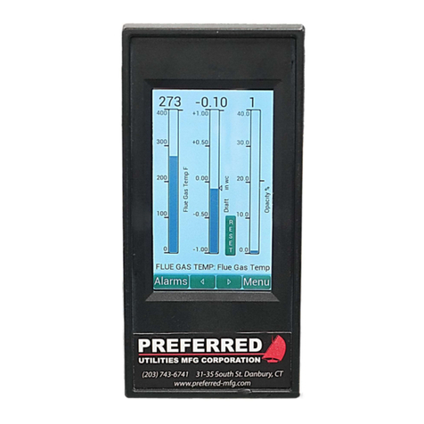
Preferred JC-22D2 Installation instructions

SDI-JC-22D2 rev. 11-1-21 page 1 of 22
Preferred Utilities Mfg Corp
Preferred Instruments div.
31-35 South Street, Danbury CT 06810
203-743-6741 www.preferred-mfg.com
JC-22D2 Sequence Draft Controller
NYC DEP Accepted
Installation & Operation Instructions
The JC-22D2 controller maintains the flue gas at a constant positive or
negative Draft by modulating the outlet damper on a boiler or furnace.
A separate 4-20mA Draft transmitter is required to modulate the damper.
The JC-22D2 interfaces to the burner flame safeguard to automatically
sequence the outlet damper Open for: Purge, Light-Off, and Post-Purge.
The sequence closes the damper after the burner shutdown to minimize
heat loss up the stack.
A separate time delayed Draft Cutout switch wired into the flame safeguard
Lockout Limits is required by Code for Safety.
The JC-22XMTR-xxCO includes a separate Draft xmtr and a separate time
delayed Draft Cutout switch in a single enclosure to reduce installation effort.
Features
Automatic Draft Control for increased boiler efficiency and reliability.
Precision Outlet Draft Control for low NOx induced FGR burners.
Firing Rate Feedforward option is included and assures stable draft during
load changes. Separate curves for up to two fuels.
Floating Draft Control mode is the easiest to tune. Floating Control can be
used with any type of actuator or an ID Fan VSD.
PID Draft Control mode is for those who prefer this type of tuning.
Automatic Damper Sequencing for purge, lightoff, post-purge burner
shutdown, and standby. Simple Flame Safeguard interface.
Damper Adjustable Start Position option is included for installations with
excessively high draft during lightoff.
High Draft Alarm with time stamped alarm and event history.
Modbus Communication with RS-485 and Ethernet capability.
Live Data Tuning Screen for more convenient tuning.
Table of Contents:
SAFETY .............................................................................. 2
Operation ............................................................................ 3
Alarms ............................................................................ 3
History ............................................................................ 3
Standard Sequence ............................................................ 4
Control Types, Control Options, and Actuators .................. 5
Control Types: Floating vs. PID ..................................... 5
Command Types: Triac vs. mA ...................................... 5
Firing Rate Feedforward ................................................ 5
Adjustable Start Position Option .................................... 5
Configuration Compatibility Chart .................................. 5
Installation ........................................................................... 6
JC-22D2 Indicator Mounting: ......................................... 6
JC-22XMTR-xxCO Mounting ......................................... 6
Damper Actuator Linkage: ............................................. 6
Wiring Requirements ..................................................... 7
BEFORE installing the wiring: ........................................ 7
Terminal Layout and Wiring Diagrams ........................... 8
Wiring Diagrams Sheet 1 of 3 ...................................... 8
Parameters / Menu Map ................................................... 12
Screen Settings ........................................................... 13
Draft Control Setpoint .................................................. 13
Tuning ......................................................................... 13
Control Options ........................................................... 14
Sequencing ................................................................. 14
Adjustable Start Menu ................................................. 15
Draft Xmtr. ................................................................... 15
Bargraph Setup ........................................................... 15
Commissioning ................................................................. 16
Triac Servo Calibration ................................................ 16
Triac Deadband Test ................................................... 16
Firing Rate Signal Calibration ...................................... 16
Controller Tuning Screens ............................................... 17
Tuning Screen Loop .................................................... 17
Firing Rate Feedforward Curve Screen ....................... 17
Live Tuning Data Screen ............................................. 17
I/O Examine - Troubleshooting ........................................ 18
Modbus ............................................................................ 19
Parts List .......................................................................... 20
Specifications ................................................................... 20
Full Size Cutout Template ................................................ 21

SDI-JC-22D2 rev. 11-1-21 page 2 of 22
SAFETY
DANGER
Electric Shock Hazard
Multiple power sources may be present.
Disconnect all electric power sources, local and remote, before servicing
WARNING
This product is intended for use in Commercial and Industrial installations,
it is NOT intended for Residential use.
This product is intended to be used by Trained Operators.
Installation, start-up, and troubleshooting is intended to be done by
Experienced Technicians familiar with Industrial Safety Codes
and all Safety Codes specific to burners and boilers.
WARNING
This product is NOT a Primary Safety Interlock rated device.
The Relay Outputs should only be used as an
additional auxiliary Operating limit and should not replace or bypass
any Primary Safety Interlock devices required by Safety Codes.
A High Draft Cutout switch and Open Damper position switch are required
to be installed and wired into the flame safeguard system.
Failure to do so can result in equipment damage, injury, or death.
If the Adjustable Starting Draft Option is used,
an additional Outlet Damper Low Fire Start position proving switch
will be required and wired into the flame safeguard low fire circuit.
Incorrect wiring connections to burner/boiler Flame Safeguard controls
can cause Equipment Damage, Injury, or Death

SDI-JC-22D2 rev. 11-1-21 page 3 of 22
Operation
Home Screen
The current boiler outlet draft pressure is displayed at the top in the selected engineering units:
“wc, cm wc, mm wc, or kPa. The Bargraph height varies in proportion to the measured draft.
The line on the right side of the bargraph is the high draft pressure alarm setpoint.
The triangle on the right is the draft control Setpoint.
The Auto/Manual button allows for manual control of the draft damper when the boiler is in
standby or released to modulate.
Press either the left or right arrow to display the large font alternate home screen.
Alarms
The lower left button on all screens indicates one of these three words:
Silence or Alarms or History
When a new Alarm occurs, Silence and the bargraph blink, and the Alarm Relay energizes.
Touch Silence to stop the blinking and to de-energize the Alarm Relay.
Alarms is displayed after silencing (if an Alarm is still active).
History is displayed when there are no active Alarms.
Active Alarms Screen
From any other screen, touch the Alarms button to display the Active Alarms Screen.
If there are no active Alarms, Alarms will not be displayed on the Home or Menu screens.
All active Alarms are displayed on this screen: High Draft Pressure Alarm, Configuration Errors,
Hardware Faults, etc….
The draft pressure and time/date shown occurred when the Alarm time delay expired and the
Alarm triggered.
When the Alarms screen is displayed, History and Home are displayed.
Touch History to display the History screen.
Touch Home return to the Home screen.
History
Touch History to display the History screen.
The History screen displays the Time/Date of the most recent 50 Alarms and Events.
Events include: when an Alarm Clears, a Shutdown Reset, JC-22D2 power-up, etc..
Touch the Up or Down arrow to advance to the next page of History. Touch Date to enter a
time/date and then to jump to the nearest History records.
The Hide Events and Show Events removes or displays Events.
The History memory is retained when powered down. The History can be extracted via the USB
port using the free JC_Edit Windows App.
Menu Screens
To set clock, Alarm Setpoints, and other initial Setup…..See pages 12-15

SDI-JC-22D2 rev. 11-1-21 page 4 of 22
Standard Sequence
Sequence
Steps
Burner Flame Safeguard Sequence
(Typical)
JC-22D2 Draft Controller
Sequence
1. Shutdown Operating Limits, Fan and Fuel Valve
inputs = OFF
Fan Delay relay output = OFF
2. Fan Start
Delay
“Call for Heat “ Operating Limits make and
energize JC-22D2 term. 15.
Burner fan starts after JC-22D2 Fan Delay
relay energizes.
The JC-22D2 commands the outlet damper to start opening and
also starts the 15 sec. (adjustable.) When the timer expires, the
Fan Delay relay closes, which completes the Burner Limits input
which starts the Burner fan. By then the outlet damper should be
open enough to prevent pressurizing the furnace with the burner
fan running.
3. Purge When both burner and outlet damper
actuators limit switches make, the Purge
starts. When Purge is complete the burner
actuator returns to low fire for Ignition.
The outlet damper continues to fully open position. The outlet
damper remains wide open.
4. Release To
Modulate
Delay
Burner main flame trial period The outlet damper remains wide open. The 15-sec. (adjustable)
release to modulate timer holds the outlet damper wide open during
the flame safeguard main flame trial period and longer if desired.
5. Modulate Burner Modulates Outlet damper modulates when the JC-22D2 is in Auto.
In Manual the operator sets the damper position.
6. Post Purge No Call for Heat
(Operating Limits and Fuel Valve inputs =
OFF, Fan remains on for post-purge)
The JC-22D2 commands the outlet damper to wide open for post
purge.
7. Damper
Close Delay
Burner completes post-purge and stops
the Fan
(Operating Limits, Fan and Fuel Valve
inputs = OFF)
Cooldown Delay timer (0 seconds, field adjustable) starts. This
timer is typically only used with refractory lined furnaces that need
an extended cooldown period. It keeps the outlet damper open for
a time delay after the Fan stops. When this timer expires, if the JC-
22D2 is in AUTO, the outlet damper moves to the fully closed.
Fan Delay Relay Output
Terminals 9-10
Operating Limit Input
Terminal 15
Fan Starter Input
Terminal 8
Fuel Valve Input
Terminal 13
Outlet Damper
12 5 6 73 1
Shutdown
Fan Start
Delay
Purge
and
Ignition
Modulation
Delay
Modulate
Post-Purge
Damper Close
Delay
Shutdown
4
open
closed
on
off
on
off
on
off
on
off
Fan Start Delay
Cooldown
Delay
Draft Modulation Delay

SDI-JC-22D2 rev. 11-1-21 page 5 of 22
Control Types, Control Options, and Actuators
The JC-22D2 allows field selection of: control types, output/actuator type etc…. The field wiring and the required auxiliary
equipment changes based on the selections made. Please read the following descriptions.
Control Types: Floating vs. PID
Floating control has (2) tuning adjustments: Deadband (DB) and Proportional Band (PB). PB slows down the actuator/VSD
rate of change (speed) as the Draft approaches the Setpoint, which makes overshoot and oscillation less likely. This makes
it easier to tune and provides very good control.
PID control has (3) tuning adjustments: Deadband (DB), Proportional Band (PB), and Integral (I) (also called “Reset”).
Instrument Technicians are typically more familiar with this type of controller tuning and can tune for tight Draft control.
However, burner technicians who are less familiar with PID tuning can improperly tune the controller and inadvertently
cause overshoot and Draft control oscillation.
Command Types: Triac vs. mA
Triac output is used with a 3 wire AC reversible actuator with Open, Close, Neutral terminals. The JC-22D2 internal solid
state Triacs energize the Open or Close outputs. Some Triac actuators have a position feedback potentiometer, such as:
models R-AL-2A, SM-xx, UM-xxx, some do not: models: PL-2A-xxx. Triac actuators without a position feedback pot
can not be used with some features, see the compatibility chart below.
4-20 mA or 0-20 mA output can be used with actuators that have with built-in “positioners” (electric or pneumatic) that move
the actuator to a position proportional to the mA command. mA outputs can also command an ID Fan VSD.
External resistors (available separately) can be used to convert the mA signal into a wide variety of DC voltage signals:
1-5V, 2-10V, 0-5V, 0-10V. The Adjustable Starting Position option can not be used with a mA Command actuator or VSD.
Firing Rate Feedforward
During a burner firing rate change, Feedforward control starts to move the damper (or VSD) before the change in burner air
flow causes the draft to deviate from the Setpoint. This is very beneficial for low NOx burners that require tight FGR and air
flow control in order to prevent combustion issues. The JC-22D2 has a Feedforward Proportional Band tuning adjustment
and has 2 “firing rates versus damper position” Feedforward curves for dual fuel burners. See the compatibility chart below.
A burner Firing Rate signal is required: 4-20mA, 0-5V, 0-10V, or Potentiometer. The Model SPS (Shaft Position Sensor)
includes linkage for jackshaft style burners
Adjustable Start Position Option
Installations with extremely tall stacks, or with an oversized ID fan, can create an excessively negative draft if the
Draft Damper wide open during light-off. This can cause nuisance pilot flame failures. The default JC-22D2 sequence
positions the damper wide open for Purge, Ignition, and Main Flame Trial.
The Adj. Start Position option positions the damper wide open for Purge and then moves to a partially closed position after
Purge completes. When the damper reaches this position, if the measured draft not sufficiently negative, the damper will jog
open until the Draft is more negative that the User set Adj. Start Draft Setpoint. When the Draft is acceptable, the
JC-22D2 Adj Start Relay Output energizes.
NOTE: This Option should NOT be used unless absolutely required by the site conditions. This Option requires a second
damper proving switch to be used as a Burner Flame Safeguard Ignition Interlock, see page 11 wiring diagram.
Configuration Compatibility Chart
Actuator Compatible Control Type and Options
Command Type Triac Feedback
Control Type Feedforward Adj. Start Position
Triac No Floating No No
Triac Yes PID or Floating Yes* Yes**
4-20 or 0-20 mA
damper or VSD N/A PID or Floating Yes* No
*The controller must have a firing rate input to use the Feed-forward option.
**The controller must have either a firing rate input or a purge/low fire DIN indication from the
FSG to use the Adjustable Start option.

SDI-JC-22D2 rev. 11-1-21 page 6 of 22
Installation
JC-22D2 Indicator Mounting:
The JC-22D2 Indicator is designed for flush mounting in an enclosure
located rated NEMA 12 or better.
The JC-22D2 should not be subjected to excessive vibration.
Continuous operation is guaranteed over the 32-131 F (0-55C) ambient
operating range.
JC-22XMTR-xxCO Mounting
The JC-22XMTR-xxCO is the standard xmtr for use with the
JC-22D2. Other 4-20 mA xmtrs may be used with the JC-22D2.
Mount the transmitter in a location that is free from excessive
vibration and that will remain at a stable temperature. To prevent
incorrect pressure measurements, the pressure tap in the duct
should be flush with the inside wall of the duct and should be
perpendicular to the primary flow pattern.
Burner flue gas contains a significant amount of water vapor, which
condenses inside the impulse tubing. If the condensed water
collects and remains in the impulse tubing, a false higher pressure
will be applied to the transmitter, which will cause improper draft
control system operation and/or nuisance burner trips.
Mounting the JC-22XMTR close to the pressure tap minimizes
condensate drainage problems.
See the SDI-JC-22XMTR-xxCO instruction manual for additional important installation details.
Damper Actuator Linkage:
The linkage arrangement between the servo actuator and the damper is
important. The wrong arrangement can make it very difficult to control the
draft at reduced firing rates.
Single blade and Parallel blade dampers have a very non-linear flow vs.
rotation characteristic. Rotating from fully closed toward open, the flow
increases very rapidly as the damper opens. The flow changes much less
near the fully open end of the rotation.
The linkage for single and parallel blade dampers should be arranged in a
'Slow Opening' configuration in order to linearize the draft control loop. Near
the Closed position, the servo rotation opens the damper very slowly.
Opposed blade dampers have a more linear flow vs. rotation characteristic.
The linkage for a properly sized opposed blade damper should be between
Linear. Oversized opposed blade dampers may require a Slow Opening
linkage arrangement.
Furnace
or
Flue Gas Duct
UP
12"
minimum
Pitch Down
2" per foot
(minimum)
for drainage.
Pressure Tap with
Clean-out Plug (1-1/4" pipe typ.)
JC-22XMTR
Must be located
ABOVE the flue gas
tapping for proper
condensate draining
Impulse Line
See text for size
Single
Blade
Parallel
Blade
Damper Style: Linkage Setup:
Damper
Servo
Slow Opening:
O
C
C
O
Opposed
Blade Damper
Servo
Linear:
O
C
C
O
Panel Cutout
3.61 x 7.65
3.88
8.00
Touch
Screen
8.74
Plug-in Terminals
1.00
4.88
Plug-in Terminals

SDI-JC-22D2 rev. 11-1-21 page 7 of 22
Wiring Requirements
DANGER
Electric Shock Hazard
Multiple power sources may be present.
Disconnect all electric power sources, local and remote, before servicing
WARNING
This product is intended for use in Commercial and Industrial installations,
it is NOT intended for Residential use.
This product is intended to be used by Trained Operators.
Installation, start-up, and troubleshooting is intended to be done by
Experienced Technicians familiar with Industrial Safety Codes
and all Safety Codes specific to burners and boilers.
This product is NOT a Primary Safety Interlock rated device.
The Relay Outputs should only be used as an
additional auxiliary Operating limit and should not replace or bypass
any Primary Safety Interlock devices required by Safety Codes.
A High Draft Cutout switch and Open Damper position switch are required
to be installed and wired into the flame safeguard system.
Failure to do so can result in equipment damage, injury, or death.
If the Adjustable Starting Draft Option is used,
an additional Outlet Damper Low Fire Start position proving switch
will be required and wired into the flame safeguard low fire circuit.
Incorrect wiring connections to burner/boiler Flame Safeguard controls
can cause Equipment Damage, Injury, or Death
BEFORE installing the wiring:
Consult with the burner control system designer to determine which wiring options on the following pages
should be installed. The JC-22D2 has field selectable options for: Control Type, Actuator type,
Feedforward, Sequence, etc..
All wiring must comply with all local and national electrical codes. Tighten all terminals to 4.4 in-lb. Wire must be stranded
copper, 12-24 ga., 150V / 75 C insulation minimum.
AC and DC wiring must be separated and must not be run in the same conduit to prevent electrical noise coupling.
Use shielded cables where shown, connect shields only where shown, insulate all other shields to prevent accidental
grounding.
Ignition transformer and motor VFD wiring are particularly noisy and should be kept away from all AC and DC wiring.
Relay contacts are rated: 10 A resistive, 9 FLA / ½ Hp / 120 Vac
If the 4-20 mA output will not be used, jumper terminal 42 to 43 to prevent the OUTPUT FAILURE error message.
RS485 is electrically Isolated from all other DC and AC wiring.
All DC '-', terminals are connected together internally.
Terminals 1-20 are Line Voltage AC. Terminals 31-60 are low voltage DC.
An external Line Voltage supply switch or circuit breaker, marked as the disconnect for this instrument, suitably located and
easily reached, and complying with IEC 60947-1 and -3 must be provided.
Fuse: 3.15 amp Slo-Blo, 250 V, 5x20mm (Littlefuse 02393.15HXP, Belfuse 5TT 3.15-R, Preferred Utilities 16740-3.15S)
2 amp Slo-Blo, 250 V, 5x20mm (Littlefuse 0239002.HXP, Belfuse 5TT 2-R, Preferred Utilities 16740-2S)
Caution: To reduce the risk of fire, only replace fuses with the same type.

SDI-JC-22D2 rev. 11-1-21 page 8 of 22
Terminal Layout and Wiring Diagrams
Wiring Diagrams Sheet 1 of 3
L1
L1
N
N
4
3
2
1
8
7
6
5
50
48
46
44
42
40
38
36
34
32
49
47
45
43
41
39
37
35
33
31
Main
Board
USB
Ethernet
3.15A
Slo Blo
N
19
18
17
16
15
14
9
13
12
11
10
60
59
58
57
56
55
54
53
52
51
Future
Rmt I/O
Aux
Board
USB
2A
Slo Blo
20
Low Voltage DC terminals
31
+24 Vdc
32
2.5Vref
33
DC -
34
AIN 1
35
+24 Vdc
JC-22XMTR term 1, 4-20mA "+"
36
AIN 2
JC-22XMTR term 2, 4-20mA "-"
37
+24 Vdc
38
AIN 3
39
DC -
40
AOUT 1
41
DC -
42
AOUT 2
Damper (or VSD) 4-20mA Command
43
DC -
Damper (or VSD) 4-20mA Command
44
DC DIN 1
Remote Alarm Silence
45
RS485 A+
46
DC DIN 2
Burner at Purge Position
47
RS485 B-
48
DOUT 1
49
RS485 Com
50
DOUT 2
51
+24 Vdc
52
2.5Vref
Actuator Feedback Pot Closed
53
AIN 3
Actuator Feedback Pot Wiper
54
DC -
Actuator Feedback Pot Open
55
+24 Vdc
Burner Firing Rate, Vdc or mA
56
AIN 4
Burner Firing Rate, Vdc or mA
57
DC -
Burner Firing Rate, Vdc or mA
58
future
59
future
60
future
Line Voltage AC terminals
N
N
N
N
L1
L1
L1
L1
1
ROUT 1 NO
Common Alarm
2
ROUT 1 C
Common Alarm
3
ROUT 1 NC
4
ROUT 2 NO
5
ROUT 2 C
6
ROUT 2 NC
7
AC DIN 1
Burner at Purge Position
8
AC DIN 2
Fan Starter Energized
9
ROUT 3 NO
Fan Start Delay Contacts
10
ROUT 3 C
Fan Start Delay Contacts
11
ROUT 4 NO
Adj Start at Position
12
ROUT 4 C
Adj Start at Position
13
AC DIN 3
Fuel Valve Energized
14
AC DIN 4
Fuel 2 Select
15
AC DIN 5
Operating Limits Made
16 Close Triac Damper Actuator x Vac CLOSE Cmnd.
17 Open Triac Damper Actuator x Vac Open Cmnd.
18 Triac Power
Input
Actuator 24-120Vac Power Input
19 Actuator Neutral
20 Fused 120 Vac
Output
N
N

SDI-JC-22D2 rev. 11-1-21 page 9 of 22
Typical JC-22D2 Interfacing to a Burner Flame Safeguard
L1
L2
G
3
P
JC-22D2
Draft
Controller
35
36
39
+24 V
+
-
4
L2
G
L1
L2
G
L1
N
Draft Sensor and
High Pressure Switch
Model: JC-22XMTR-xPCO
15
9
10
6 13
Operating Limit
Fan Start
Delay
Contacts
Non-Recycling / Lockout Limits
3
7 P
Draft / Pressure
Connection
T1-1 R
T1
5 sec
Off Delay
blk
wht
red
red
4-20 mA
" WC Xmtr
+
-
1
2
Low Voltage DC
Do not run in Conduits with AC
H
N
G
120 Vac
60 Hz
26 VA
Fireye
E100/E110
Honeywell
RM7800L
Existing Burner Flame Safeguard:
WARNING:
* Some Flame Safeguard Wiring is Omitted for Clarity.
* Consult Burner Manual for Complete Wiring Diagram.
* An Experienced Burner Technician must adapt this TYPICAL
wiring diagram to each specific burner wiring diagram.
Fireye
YB110
Safety Interloc k (required by Co de)
Burner
Flame
Safeguard
120 Vac
60 Hz
99 7 13
8
M
D
8
Low Fire Proving Switches
Purge Proving Switches
Fan
Fan
Fuel Valve
Fuel Valves
Draft Purge Interlock (required by Code)
Fireye
E100/E110
Honeywell
RM7800L
Fireye
YB110
D
M
8
18
5
19
RM7800 / YB110
E100 / E110
For Draft Damper Actuator
and ID Fan VSD wiring
See sheet 2
For Additional Options
See sheet 3
Fan
Operating Limits
Legend:
Existing AC Wire (Do NOT change this wiring)
Remove Existing AC Wire
New AC Wire
New Shielded Low Voltage DC Cable
Do Not Run in Conduits with AC Wires

SDI-JC-22D2 rev. 11-1-21 page 10 of 22
Wiring Diagrams Sheet 2 of 3
Damper Actuator (or ID Fan VSD) Wiring
Damper Actuator or ID Fan VSD
42
43
-
+
Draft Purge Interl ock (required by Co de)For an Actuator:
Draft Purge Interl ock (required by Co de)
Input:
4-20mA, 0-20mA,
1-5V, 2-10V ,
0-5V, 0-10V
+
-
Command: 4-20mA or 0-20mA
Feedback: None
Command/Output Input Resistor
4-20 mA 4-20 mA none
4-20 mA 1-5 V 250 ohms
4-20 mA 2-10V 500 ohms
0-20mA 0-20mA none
0-20mA 0-5V 250 ohms
0-20mA 0-10V 500 ohms
JC-22D2
Resistors not included, order Separately
Actuator Compatiblity
YES: Floating Control, PID, Feedforward
NO: Adj. Start.
54
53
52
+2.5 V
+
-
CW
CCW
16
17
OPEN
CLOSE
18
20
To Reverse
Rotation
Swap Wires
on Terminals:
16 & 17
52 & 54
fused 120 Vac output
Triac Power Input
3
14
CW
CCWEXT
RET
510
69
5
711
EXT
RET
OPEN
CLOSE
0.15 – 2.29 Vdc
2
3
Low Voltage DC
Do not run in Conduits with AC
131
142
EXT
RET 7
Draft Purge Interlock (required by Code)
Bias Resistors are required for some feedback pot styles.
Not needed for SM-xx actuators. See Instructions.
Resistors not included, order Separately
SM-15, SM-37
R-AL-2, R-AL-2A
Actuator
Terminals:
6
EXT
RET
Command: Triac
Feedback: Pot
Potentiometer Spec:
500 - 10,000 ohms
JC-22D2
Actuator Compatiblity
YES: Floating Control, PID,
Feedforward, Adj. Start.
16
17
OPEN
CLOSE
18
N
20
fused 120 Vac output
Triac Power Input
24Vac Damper Actuator
120 V 24 V
Draft Purge Interlock (required by Code)
Damper Open
Switch
Command: Triac
Feedback: None
To Reverse
Rotation
Swap Wires
on 16 & 17
JC-22D2
Actuator Compatiblity
YES: Floating Control
NO: PID, Feedforward, Adj. Start.
SM-15, SM-37
PL-2, PL-2A
Actuator
Terminals:
120 Vac Damper Actuator
16
17
OPEN
CLOSE
18
19
20
Damper Open Switch
To Reverse
Rotation
Swap Wires
on 16 & 17
fused 120 Vac Output
Triac Power Input
5
3
14
138
146
CW
CCWEXT
RET
EXT
RET 7
3
2
JC-22D2
Draft Purge Interl ock (required by Code)
Command: Triac
Feedback: None
Actuator Compatiblity
YES: Floating Control.
NO: PID, Feedforward, Adj. Start.
Made from
90-100% Open.
Made from
90-100% Open.
Damper Open Switch
Made from
90-100% Open.
Damper Open Switch
Purge Air Flow Switch
For an ID Fan VSD:
N
19
Note
Terminal 20 is connected to the
internal Triac surge suppressors
Note
Terminal 20 is connected to the
internal Triac surge suppressors
Note
Terminal 20 is connected to the
internal Triac surge suppressors
19
N

SDI-JC-22D2 rev. 11-1-21 page 11 of 22
Wiring Diagrams Sheet 3 of 3
Feedforward, Adj. Start, Miscellaneous Wiring
Burner Firing Rate Signal Types
(choose one), required for the Feedforward Option
52
56
57
+
Low Fire
High Fire
Potentiometer Signal
0.15 – 2.29 Vdc
Low Voltage DC
Do not run in Conduits with AC.
Connect Shields only where shown.
Potentiometer Spec:
500 - 10,000 ohms
linkage to burner
Model SPS or equal
+2.5 VHi Fire
-Low Fire
JC-22D2
56
57
+
4-20mA Signal
+
-
-
Firing Rate
4-20 mA Output
from
Burner Controls
(Order Separately) 100k
56
57
+
0-5V or 0-10V Signal
(or any 2V min. span)
+
-
-
Firing Rate
Voltage Output
from
Burner Controls
Miscellaneous Optional Wiring
41
L1
2
1
44
N
ROUT 1 C
ROUT 1 NO
Alarm
Horn
24 Vdc Remote
Alarm Silence
Pushbutton
DC DIN 1
-
RS485
Isolated
A +
B -
Isolated
Common
45
47
49
ORG
BLU
WHT
ORG
BLU
WHT
Belden 3106A
or equal
JC-22D2
JC-22D2
Adjustable Starting Draft Sequence Option Wiring
7
AC DIN 1
Low Fire
Proving Switches
Purge
Proving Switches
Draft Purge Interlock
(required by Code)
Fireye
E100/E110
Honeywell
RM7800L
Fireye
YB110
Made from
90% to 100% Open.
Draft Damper
Position Switches
Draft Adjustable Start Interlock
(required by Code)
JC-22D2
12
11
Adj. Start
Relay Made from the
Adj. Start position
up to 100% Open.
SM-x and UM-x servos
include (2) aux. switches
All wiring on Sheet 1 is also required
All wiring on Sheet 2 for Command: Triac / Feedback: Pot is also required
A signal indicating when the burner is at the Purge Position is required.
There are 3 options, choose one: Burner Firing Rate Signal (above), AC DIN 1, or DC DIN 2.
46
33
DC DIN 2
-
Compatible with RM7800L or YB110 (NOT allowed for E100/E110)
24 Vdc Purge position limit switch
M
D
8
D
M
8
18
5
19
120 Vac Purge position signal
L1
14
120 Vac
Fuel 2 FF Curve Select
Fuel 2
Feedforward Curve
Select

SDI-JC-22D2 rev. 11-1-21 page 12 of 22
Parameters / Menu Map
From the Home screen, touch Menu to display the Main Menu.
Tuning Live Data
Draft
Draft Setpoint
Proportional Term
Feedforward Term
Output
Control Options
Control Type
Command Type
Triac Feedback Type
Firing Rate Signal Type
FR Feedforward Option
Sequencing Menu
Utilities
Set Clock
Calibrate Touch
Clean Screen
Screen Settings
Firmware Version
Startup History
Pasword
Enter
Change
Logout
Screen Settings
Brightness
Touch Buzzer
Alarm Buzzer
Main Menu
Utilities
Password
Draft Control Setpoint
Tuning
Alarm
Configure/Setup
I/O Examine
Alarm
Low Draft Alarm Setpoint
Alarm Delay Seconds
Configure/Setup
Control Options
Inputs / Outputs
RS485
Ethernet
Calibrate Firing Rate
Start Auto Calibration
FR Volts/mA at 100%
FR Volts/mA at 0%
Sequencing
Fan Start Delay
Draft Modulate Delay
Cooldown Delay
Adj. Start Position Option
Adjustable Start Menu
Adj Draft Ignition Position
Purging Input
Firing Rate % at Purge
Fuel 1 Draft Ign. Position
Fuel 2 Draft Ign. Position
Ignition Draft Setpoint
Bargraph Setup
Bargraph Top Draft
Bargraph Bottom Draft
BG Tick Decimal Digits
Draft Xmtr Setup
Draft Xmtr Units
Xmtr 20mA = ? Draft
Xmtr 4mA = ? Draft
Draft Decimal Digits
Draft Xmtr Name
Bargraph Setup
Triac Servo Calibration
Auto Calibration
Volts at 100% (Open)
Volts at 0% (Closed)
Triac Servo Stroke Sec.
Tuning Screens Loop
Inputs / Outputs
Draft Xmtr
Triac Servo Cal.
Triac Deadband Test
Firing Rate Signal Cal.
Triac
Deadband Test
Tuning
Draft Proportional Band
Draft Deadband
Xmtr Smoothing Filter
More Tuning
Feedforward Prop. Band
PID Minutes/Repeat
Output Rate Limiter
Auto Max Output
Auto Min Output
Feedforward Curv e
Curve Data Entry Screen
Control Options Factory Defaults are:
Control = Floating, Command = Triac, Feedback = None
Parameters that are grayed out are ignored.
Changing Control Options enables those parameters.
Some Combinations of Options are Not Allowed,
Always do the Config. Error Check after changing Options
Only displayed when
Feedforward Option is
Enabled

SDI-JC-22D2 rev. 11-1-21 page 13 of 22
Parameters
Screen Settings
Parameter
Default
Max.
Min.
Go
to: Menu > Utilities > Screen Settings
1 Disable Enable Disable
Touch Buzzer Enable
Activates faceplate Tone when a
screen item is touched
2
Disable
Enable
Disable
Alarm Buzzer Enable
Activates faceplate Tone when a
n Alarm is triggered.
Draft Control Setpoint
Parameter
Default
Max.
Min.
Go to: Menu > Draft Control Setpoint
40 -0.10 +200.00
-200.00
Draft
Control Setpoint
See: Draft Xmtr Setup for the Units
Tuning
Parameter
Default Max. Min. Go to: Menu > Tuning
41 0.25 25.00
0.025
Draft Proportional Band
Expressed in the same units/scaling of the Draft Xmtr (see Draft Xmtr Setup menu)
Smaller values cause more aggressive control action.
Larger
values cause less aggressive
control
action.
42 0.030 1.500
0.003
Draft Deadband
Expressed in the same units/scaling of the Draft Xmtr (see Draft Xmtr Setup menu)
If the draft pressure is with +/- Draft Deadband of the setpoint, the damper stops.
Smaller Deadband increases damper movement and allows for tighter control.
Setting the deadband too low can cause draft damper oscillation/hunting
Larger
values decrease damper movement but limit control pre
cision.
43 2.0 5.0 0.5
Xmtr Smoothing Filter (seconds)
Smooths out normal combustion pressure pulsations.
Smaller values reduce smoothing (Too small can cause damper hunting).
Larger
values ca
us
e more smoothing. (Too large can ca
us
e overshoot
oscillations
).
44 125 1000
75 Feedforward Prop. Band
Determines how the Damper/VSD responds to a change in the Burner Firing Rate.
Smaller proportional band will cause more aggressive Feedforward action.
L
arger
proportional band will cause less aggressive
Feedforward
action.
45 0.50 4.00 0.12 PID Minutes/Repeat
Proportional Band responds instantly to a Draft disturbance. After that, PID “Repeats”
ramps the damper back to the Draft Setpoint.
Smaller minutes/repeat will cause faster ramping (Too small causes oscillation).
Larger minutes/repeat will cause slower ramping.
46 30 75 25 Output Rate Limiter Sec./100%
Only affects Floating control mode. Prevents the damper from moving too fast.
Smaller Sec/100% allows damper to move faster.
Larger Sec/100% limits the damper speed.
This
value
should
always
be set to longer than the actuator
0
-
100%
stroke time.
47 100.0 100.0
0.0 Auto Max Output
When Released to Modulate AND in AUTO, this is the maximum damper opening.
This prevents “Reset Windup”. Otherwise, the Damper can stroke the full 0-100%.
Auto Max
Output
m
ust be
greater than
:
(Auto Min
Output
+ 25
)
48 0.0 100.0
0.0
Auto Min Output
When Released to Modulate AND in AUTO, this is the minimum damper opening.
This prevents “Reset Windup”. Otherwise, the Damper can stroke the full 0-100%.
Auto Min
Output
must be Less than
:
(Auto Max
Output
-
25)

SDI-JC-22D2 rev. 11-1-21 page 14 of 22
Draft Alarm
Parameter
Default
Max.
Min.
Go
to: Menu >
Alarm
52 2.00 250.0 -250.0
Alarm
Setpoint
Draft Alarm will only activate when the boiler is released to modulate.
Alarm activates when Draft is more positive than this Setpoint for longer than the Alarm
Delay. Example: Draft =
-
0.10”, Alarm SP =
-
0.20”,
Alarm activates after Delay.
53 8 60 1
Alarm
Delay (se
conds)
Draft Alarm time delay, see Alarm Setpoint description.
Control Options
Parameter
Default
Max.
Min.
Go
to: Menu > Configure / Setup >
Control Options
55 Floating PID Floating
Control Type
Options: PID
or
Floating
See pg 5
Compatibility
chart
56 Triac 4-20mA Triac Actuator or VSD Command Type
Options: Triac / 4-20mA / 0-20mA
With an external resistor, 0-20mA can drive 0-5V or 0-10V devices.
See pg 5
Compatibility
ch
art
57 None Pot. None Triac Feedback Type
Options: None / Potentiometer
See pg 5
Compatibility
chart
58
Disable
0
-
10V
Disable
Firing Rate Signal Type
Options: Disabled / 4-20mA / Potentiometer / 0-5V / 0-10V
Firing rate signal input is required for
the Feedforward control option.
59
Disable
Enable
Disable
F
iring Rate
Feedforward Option
Options: Disable / Enable
See pg 5
Compatibility
chart
Sequencing
Parameter
Default
Max.
Min.
Go
to: Menu > Configure / Setup >
Sequencing
65 15 60 1 Fan Start Delay Seconds
When the Operating Limits input makes: the draft damper starts to drive fully open and
the timer starts timing. The JC-22D2 Fan Start Delay Relay energizes at the end of the
delay and energizes the FSG Operating Limits input.
This delay allows the Draft damper to get enough open to prevent pressurizing the
boiler when the burner FD fan starts. This delay prevents a nuisance Draft Cutout
Lockout during startup.
6
6
15
60
0
D
raft Modulate Delay Seconds
This sets the delay after the fuel valves are opened before the draft damper can begin
to start modulating.
If the adjustable start position option is being used, the modulate delay must be set for at
least as long as the MTFI.
67 0 900 0 Cooldown Delay Seconds
This keeps the damper wide open for the selected seconds after a burner shutdown.
Note: T
he cooldown delay will only activate if the burner had been released to modulate
for at least 60 seconds.
68
Disable
Enable
Disable
Adjustable Start Position Option
Options: Disable / Enable
The JC-22D2 must have either a firing rate input or FSG purge position input to use the
adjustable start position option. See additional Code required Interlock, see page 11.
The Adj. Start parameters are in the next Menu screen.

SDI-JC-22D2 rev. 11-1-21 page 15 of 22
Adjustable Start Menu
Parameter
Default
Max.
Min.
Go
to: Menu > Configure / Setup > Sequencing > Adjustable Start Menu
70 AIN 5 AIN 5
AC_DIN1
Burner Purging Input
Options: AC_DIN 1 / DC_DIN 2 / AIN 5
This signal indicates when the burner is at the Purge position
. See
page 5 des
cription.
71 90 95 50 Firing Rate % at Purge
If AIN 5 is selected as the Burner Purging Position input and the signal is greater than
this parameter, the Adj. Start sequence detects that the burner is Purging.
See page
5
description.
72 35 50 10 Fuel 1 Draft Ign. Position
When the JC-22D2 Fuel 2 input is de-energized,
the draft damper will go to this position
before checking adjustable start draft.
See page
5
description.
73 35 50 10 Fuel 2 Draft Ign. Position
When the JC-22D2 Fuel 2 input is energized, the draft damper will go to this position
before checking adjustable start draft.
See page
5
description.
74 -0.25 -0.1 -8.0 Ignition Draft Setpoint
Once the damper has reached the adjustable start position, If required, the damper will
will slowly jog
open D
raft
is more negative than
this setpoint.
See page
5
description.
Draft Xmtr.
Bargraph Setup
Parameter
Default
Max.
Min.
Go
to: Menu > Configure / Setup > Inputs / Outputs >
Draft Xmtr > Bargraph Setup
87
1.00
250.0
-
250.0
Draft at Bargraph Top
This sets the scale at the top of the bargraph.
88 -1.00 250.0
-250.0
Draft at Bargraph Bottom
This sets the scale at the bottom of the bargraph.
89
2
3
1
BG Tick Decimal
Digits
The number of decimal digits displayed at the bargraph 0%, 25%, 50, 75%,
and 100% marks.
Parameter
Default
Max.
Min.
Go to: Menu > Configure / Setup > Inputs / Outputs > Draft Xmtr
80 In. wc
kPa In. wc Draft Xmtr Units
Options: in. wc / cm wc / mm wc / kPa
This is the Units text used on various screens.
Changing the Units does NOT change, or re-calculate, or any other parameter’s
numeric value
…such as the Control setpoint, Alarm setpoint, etc…
8
1
-
1.0
250.0
250.0
Xmtr 20 mA = ?? Draft
Draft transmitter 20 mA calibration value.
Fail Safe design for a xmtr or field wiring fault, typically means the xmtr 20 mA
calibration
should
correspond to the
more
negative
value
.
82 1.0 250.0
-250.0 Xmtr 4 mA = ?? Draft
Draft transmitter 4 mA calibration value.
Fail Safe design for a xmtr or field wiring fault, typically means the xmtr 4 mA
calibration should correspond to the
more positive value
.
8
3
2
3
1
Draft Decimal Digits
The number of digits
displayed on the screen to the right of the decimal point.
84 Draft Econ
Outlet
Draft Draft Xmtr Name
Options: Draft / Furnace / Outlet / Econ Outlet

SDI-JC-22D2 rev. 11-1-21 page 16 of 22
Commissioning
Triac Servo Calibration
Menu > Configure/Setup > Inputs/Outputs >Triac Servo Cal.
A Triac servo with a feedback pot must be stroked and the
0% and 100% feedback voltages must be stored before the
draft controller is run in automatic.
Initially this screen is in Manual and the damper servo can
be opened/closed in order to check rotation, and to set the
travel limit switches. Verify that there is no linkage or
damper binding, and that the servo stops before the
damper hits a hard stop at both ends of travel. Verify that
the Pot voltages at full Open and Closed are in the ranges
shown on the screen (if needed, correct the Pot wiring).
After the Manual checks are completed, press Manual to
change to Auto mode. To prevent injury: Verify that no
one is near the servo or damper .
Press Start to initiate the automated Calibration cycle. The Start button then changes to Stop. Press Stop at any time to stop
servo movement (which also aborts the cycle). The automated calibration cycle is:
Close output energizes. The closed limit switch stops the servo, Pot voltage settles, 0% Pot Vdc is stored.
Open output energizes. The open limit switch stops the servo, Pot voltage settles, 100% Pot Vdc is stored.
Close output energizes. The seconds to move 100% -> 0% is measured and stored.
Mode changes to Manual
Triac Deadband Test
Menu > Configure / Setup > Inputs / Outputs >Triac Deadband Test
Place the Servo Command in Manual. During the following observe how close the servo
comes to the command, and whether the servo hunts before finally stopping.
Set the command to 30%, then 20%, then 10%, then 20%, then 30%, etc…
Reduce the deadband and repeat until:
Deadband is at the minimum value or the servo hunts
If the servo hunts, increase the deadband gradually until the hunting stops, then test again.
Firing Rate Signal Calibration
Menu > Configure / Setup > Inputs / Outputs > Firing Rate Signal Cal
The Firing Rate input can NOT be calibrated when:
The burner is firing AND ( Feedfoward is Enabled OR Adj. Start Position is Enabled )
Firing Rate CAN be calibrated when firing IF (Feedfoward and Adj. Start are both disabled).
To calibrate the firing rate input:
Use the burner firing rate controls to position the burner at Low Fire.
When the signal settles, press “Save 0% Signal”.
Use the burner firing rate controls to position the burner at High Fire.
When the signal settles, press “Save 100% Signal”.
Use the burner firing rate controls to gradually move the burner from 100% to 0%.
If the JC-22D2 displayed “% Firing Rate” does not approximately track the burner,
trouble shoot the wiring and/or the firing rate sensor.

SDI-JC-22D2 rev. 11-1-21 page 17 of 22
Controller Tuning Screens
Tuning Screen Loop
The tuning screens are in a loop to
allow you to change a value and then
to quickly get to the “Live Data”
screen to watch how the controller
responds. Use the right/left arrows in
the title bar to move through the loop.
The “More Tuning” and/or “Feedforward” screens are skipped over if the related options are Disabled.
See the descriptions for each of the tuning parameters, and how it affects the tuning, on page 13.
Firing Rate Feedforward Curve Screen
With a Tech level password, Feedfoward Curve data can be manually entered/edited at any
time (burner firing, or not firing), just touch one of the feedforward values. When Released to
Modulate, the Store button method or the manual method can be used to enter curve data.
Store Button method (Tech Password required and Draft is Released to Modulate)
When the Manual/Auto button is in Auto, the controller moves the damper until the Draft
is within the Setpoint Deadband. In Manual the User enters the “% Damper” value.
Put the Burner controller in Manual and position the burner at any firing rate within
+/- 2% of any Curve Firing Rate, and keep the burner fixed at that firing rate.
** is displayed when within +/-2%. --- is displayed when NOT within +/-2%
When the Draft is near the Draft Setpoint, change the Auto/Manual button to Manual to
hold the draft damper at a fixed position
Press Store to save that damper position in the curve
Repeat
Live Tuning Data Screen
This screen allows you to watch how the Proportional, Integral (aka “Reset”) and feedforward
settings affect the Draft control. See the descriptions for each of the tuning parameters, and
how it affects the tuning on page 13.
After making a tuning value change these two methods should both be used to test the draft
controll tuning:
Leave the Draft in Auto and make the burner firing rate change (at a realistic ramp rate).
Put the draft in Manual, open the damper 5-15% for 10-15 sec, and then put the Draft in
back in Auto.
If control is sluggish control (slow return to Setpoint without overshoot), gradually decrease
the Proportional Band.
If control is overly aggressive control (Draft overshoots the setpoint and cycles excessicely
before settling), gradually increase the Proportional Band.
If the burner firing rate is not changing, and the damper is hunting, gradually increase the
Deadband.
If the burner firing rate is not changing and the draft Damper is in Manual (not moving), and the draft xmtr signal is jumping
excessively, increase the filter sconds gradually. If the draft signal is not jumping much at all, the Filter Seconds must be
decreased because excessive Filter seconds will cause the controller to overshoot.
Tuning Live Data
Draft
Draft Setpoint
Proportional Term
Feedforward Term
Output
Tuning Screens Loop
Tuning
Draft Proportional Band
Draft Deadband
Xmtr Smoothing Filter
More Tuning
Feedforward Prop. Band
PID Minutes/Repeat
Output Rate Limiter
Auto Max Output
Auto Min Output
Feedforward Curve
Curve Data Entry Screen
Main
Menu

SDI-JC-22D2 rev. 11-1-21 page 18 of 22
I/O Examine - Troubleshooting
The I/O Examine screen shows the current values for all JC-22D2 inputs and outputs and is very usefull for detecting wiring and
sequencing problems.
Verify that JC-22D2 “N” is connected to Flame Safeguard “N”
Check the Alarms screen to verify that there are no Configuration Errors.
Correct Errors (see Compatability Chart on page 5)
The damper will not open/close when: JC-22D2 is in Manual and I/O screen shows: Start Limits=Off, Fan=Off, Fuel Valve=Off
For Triac actuators:
To test, change to Floating Control and “No Feedback”.
Check the 2A fuse
Check the actuator (or VSD) wiring, page 10.
Damper doesn’t Open for Purge when burner Operating Limits Make
Use I/O screen to verify: Start Limits = ON.
If Off, check wiring, see page 9. Verify that JC-22D2 “N” is connected to Flame Safeguard “N”
Burner won’t start
Use I/O screen to verify: Start Limits = ON and that the Fan Start Relay = ON after the Fan Start Delay timer expires.
Then check wiring, see page 9. Verify that JC-22D2 “N” is connected to Flame Safeguard “N”
The damper opens for Purge, stays wide open and will not modulate when the burner is firing
Check the I/O screen to verify: Fuel valve = ON
If I/O shows fuel valve is OFF:
Check the wiring.
Verify that the JC-22D2 120 Vac Neutral is wired to the Flame Safeguard Neutral.
If Fuel valve input = ON, with the JC-22D2 in Manual, can the Damper be Closed and Opened?
If NO:
Check the Close Triac wiring to the actuator, page 10.
If YES:
Is the Draft Setpoint more Negative than the Draft?
If YES, the damper should stay wide open, there is no problem.
Examples of “More Negative”: SP = -0.2”, Draft = -0.1” and SP = +0.15, Draft = +0.2”
Damper closes before burner Post Purge is completed
Check the I/O screen to verify: Fan Run Command = ON during Post Purge

SDI-JC-22D2 rev. 11-1-21 page 19 of 22
Modbus
RS485 Baud: 4800, 9600, 19200, 38400, 57600
RS485 Parity: Odd, Even, None
Ethernet: 10/100 Mb/s
Protocol: RTU
Address: 1-247
Register Formats: 16 bit Signed Integer and 32 bit Floating Point
Modbus Commands: 01 Read Coils, 03 Read Registers, 05 Write Single Coil, 06 Write Single Register,
16 Write Multiple Registers (2 registers max)
Max Poll Size: 120 coils or registers (except Code 16)
Coil
0 =
1 =
Description
98
WO
Alarm Silence
Remote Alarm Silence
99
RO
No Alarm
Alarm
Common Alarm
120
RO
No Alarm
Alarm
High Draft Alarm
121
R
O
Auto
Manual
Auto/Manual
1
22
RO
Fan OFF
Fan ON
Fan Energized Input
123
RO
De
-
Energized
Energized
Fuel Valve Energized Input
124
RO
Limits OFF
Limits ON
Start Limits Input
125
RO
De
-
Energized
Energized
Burner Start Delay Relay
Register
Type
Description
40
200
RO
F
LOAT
Filtered Draft PV
40202
R
O
F
LOAT
Draft Control Setpoint
40204
R
O
F
LOAT
Actuator Position Command

SDI-JC-22D2 rev. 11-1-21 page 20 of 22
Parts List
Part Number Description
JC-22D2 Draft Controller
16740-2S FUSE, 2 A, SLO-BLO, 250 V, 5x20mm
16740-3.15S 3.15 amp Slo-Blo, 250 V,5x20mm fuse
90437-KIT JC-xxD2 Panel Mounting Clip (2)
90434 JC-xxD2 Panel Mounting Gasket
92791 8 pt Terminal Block, line voltage, 5.08mm
92794 5 pt Terminal Block, line voltage, 5.08mm
92795 10 pt Terminal Block, low voltage, 3.81mm
92799 2 pt Terminal Block, line voltage, 5.08mm
92800 10 pt Terminal Block, line voltage, 5.08mm
JC-22XMTR-HPCO +1” to -1” 4-20mA Draft Transmitter with 4 sec High Pressure Cutout (Positive Setpoint)
JC-22XMTR-LDCO +1” to -1” 4-20mA Draft Transmitter with 4 sec Low Draft Cutout (Negative Setpoint)
JC-22-HDPCO-8 +0.05” to +9”, Draft Cutout Switch, 8 Second Delay
JC-22-HDPCO-8 -0.05” to -9”, Draft Cutout Switch, 8 Second Delay
190388-xx 10’’ thru 48” dia, E-Link Draft Damper assy with Triac actuator and JC-22XMTR-HPCO.
107362-D2-1 JC-xxD2 Single Unit, Wall Mount Enclosure, 12h x10w x 8d
107362-D2-2 JC-xxD2 Dual Unit, Wall Mount Enclosure, 14h x12w x 8d
107362-D2-3 JC-xxD2 Three Unit, Wall Mount Enclosure, 14h x16w x 8d
190751-D2 JC-xxD2 or TG-EL-D4B Adapter Plate, Panel Cutout: 7.5” X 7.6”
190753-D2 JC-xxD2 or TG-EL-D4B Adapter Plate, Panel Cutout: 8.00” X 10.75”
Specifications
Mechanical:
Enclosure: Nema 12 Faceplate, Indoor Locations
Bezel: 3 7/8 w x 8 h x 1 d
Rear Case: 3 1/2 w x 7 9/16 h x 4 7/8 d
Panel Cutout: 3.61 w x 7.65 h
Weight: 2 lbs
Ambient: 32-131 F (0-55 C)
Altitude: 6560 feet (2000 meters)
Electrical:
Input Power: 120Vac +/-15%, 50/60 Hz, 26 VA
Output Power: 24 Vdc, 300mA max combined load
Terminals: 31,35,37,40,42
Analog Inputs
(3) 16 bit, 5 samples/sec, 50/60Hz filter: -90db
Draft: 4-20 mA
Feedback Pot: 0.15 - 2.29 Vdc
Burner Firing Rate: 4-20mA, 0-2.3V, 0-5V, 0-10V
field selected
Analog Output
(1) 16 bit, 4-20mA, max 650 ohm load
Servo/VSD Command
AC Discrete Inputs
(5) 120 Vac, 13 mA typ/ch., opto-isolated
Oper. Limits, Fan Running, Fuel Valve, Fuel 2 Select,
Burner at Purge
DC Discrete Inputs
(2) Sinking, 33k / 24V internal pull-up
Remote Alarm Silence, Burner at Purge
Relay Outputs
(2) SPDT, (2) SPST, 120Vac,10 A
Alarm, Fan Start Delay, At Adj. Start
Triac Outputs
(2) 24-120 Vac, 2A fuse, opto-isolated
Actuator Open, Close
Commmunications
USB: non-isolated, JC_D2Edit config & Firmware Flashing
RS485: Isolated, 4.8 - 57.6 kbaud, Modbus RTU
Ethernet: 10/100 Mb/s, Modbus/TCP
Table of contents
Other Preferred Controllers manuals
Popular Controllers manuals by other brands
Reo Elektronik
Reo Elektronik REOTRON MDW 700 operating instructions

Nacon
Nacon MG-X quick start guide
Ruijie Networks
Ruijie Networks RG-WS6008 Series Hardware installation and reference guide
VWR
VWR Powerpette Plus instruction manual
Intel
Intel G35 Express Chipset Design guidelines
BBH
BBH SMX Series installation manual
