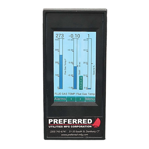
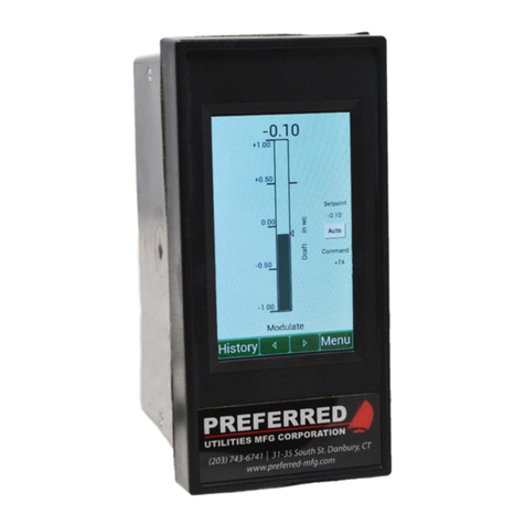
Preferred FlexFit 110 User manual

FlexFit 110 Linkageless Control
Copyright © 2018 Preferred Instruments – All Rights Reserved Worldwide
The information contained herein is provided in good faith but is subject to change without notice. It is supplied with no warranty
whatsoever and does not represent a commitment on the part of Preferred Instruments. Companies, names, and data used
as examples herein are ctitious unless otherwise stated. No part of this document may be reproduced or transmitted in any
form or by any means, electronic or mechanical, without the express written permission of Preferred Instruments.
The Preferred Instruments logo is a registered trademark ® of Preferred Instruments.
FlexFit, FlexFit Edit, and the FlexFit logo are trademarks ™ of Preferred Instruments.
All other trademarks are acknowledged as the property of their respective owners.
WARNING
If improperly installed or irresponsibly used, the equipment covered in this
manual can cause extreme property damage, severe injury, or death. It
is the responsibility of the owner and user to ensure that the equipment
described herein is installed, commissioned, and used in compliance with the
requirements of all national and local legislation, whichever may prevail.
The FlexFit is used to control potentially dangerous boiler, burner, and com-
bustion processes. Only qualied instrument engineers or senior technicians
that have read this entire manual and are familiar with all aspects of the
processes being controlled should attempt to install and commission this
controller. Only qualied operators that are familiar with all aspects of the
processes being controlled should attempt use this equipment. Failure to
do so can result in extreme equipment damage, severe injury, or death.
Revision Changes Author
1.0 Initial Release BKB

Specications iii
FlexFit – Linkageless Control – Revision 1.0 PREFERRED
UTILITIES MFG CORPORATION
FlexFit 110 Linkageless Control
FlexFit Specications ....................................................................................... vi
Safety Cautions and Warnings ........................................................................vii
Section 1 – Description 1-1
Overview ........................................................................................................1-2
Features .........................................................................................................1-2
Safety Relay ..........................................................................................1-2
Field Selectable Flex Sequence Option ................................................1-3
Servo Checks ........................................................................................1-3
Automatic Fuel SSOV Leak Test ...........................................................1-3
Lockout and Alarm History ....................................................................1-3
MAF and PAF Safe Start Checks ..........................................................1-3
High Flue Gas Temperature Shutdown .................................................1-3
Fuel Selection and Flexibility .................................................................1-3
FD VSD to VSD Bypass Changeover ...................................................1-3
Pilot Test Hold .......................................................................................1-3
Flame Scanner/Relay ............................................................................1-3
Fuel/Air Position "Pacing Logic" ............................................................1-3
Tandem Oil/Gas Valve Servo ................................................................1-4
Oxygen Trim ..........................................................................................1-4
Firing Rate Setpoint and Control ...........................................................1-4
Call for Heat ...........................................................................................1-4
Domestic Hot Water Override ...............................................................1-4
Warm Standby Option ...........................................................................1-4
Cold Start WarmUp Cycle Option .........................................................1-4
Integrated Draft Control .........................................................................1-5
RS485 Modulating Lead/Lag Interface .................................................1-5
Burner Management System .........................................................................1-5
Description of BMS Sates .....................................................................1-8
Boot ...............................................................................................1-8
Standby .........................................................................................1-8
Safe Start Checks .........................................................................1-8
Prestart .........................................................................................1-8
Purge ............................................................................................1-8
Pilot Trial for Ignition (PTFI) ..........................................................1-8
Main Trial for Ignition (MTFI) ........................................................1-8
Release to Modulate .....................................................................1-8
Assured Low Fire Cutout (ALFCO) Option ...................................1-8
Post Purge ....................................................................................1-8
Gas Valve Leak Test Option (Flex Sequence Option Only) .........1-9
Lockout .........................................................................................1-9
Interlock Groups ....................................................................................1-9
Call for Heat ..................................................................................1-9
Recycling Limits ............................................................................1-9
Fuel Select ....................................................................................1-9
Non-Recycling Limits ....................................................................1-9
Purging .........................................................................................1-9
Ignition ..........................................................................................1-9
False Flame ..................................................................................1-9
Flame Failure ................................................................................1-9
Fuel Valve Proof of Closure Switches (POCS) .............................1-9
Fan Speed ....................................................................................1-9
Combustion Control System ..........................................................................1-9
Parallel Positioning ..................................................................... 1-10
Section 2 – Installation 2-11
Electrical Noise Suppression ....................................................................... 2-12
General Wiring Requirements ............................................................. 2-12
Ignition Transformer Wiring / Mounting ............................................... 2-12
VSD Wiring .......................................................................................... 2-12
Oxygen Analyzer Wiring ...................................................................... 2-12
Flame Scanner Wiring ......................................................................... 2-12
Installation Warnings and Notes .................................................................. 2-13
Flex Sequence Option ......................................................................... 2-13
Burner Management System (Flame Safeguard) Installation ..................... 2-14
Combustion Control Installation ................................................................... 2-18
Variable Speed Drive Installation .................................................................2-20
Servo Installation .........................................................................................2-21
Servo Description and Operation ........................................................2-21
Servo Control Board ...................................................................2-22
Travel Limit Switches ..................................................................2-23
Servo Mechanical Installation .............................................................2-24
Servo Wiring ........................................................................................2-24
QD1 Quick Disconnect Cables ...........................................................2-26
Flame Scanner/Relay ...................................................................................2-27
Flame Status .......................................................................................2-27
Flame Relay ........................................................................................2-28
Self-Checking ......................................................................................2-28
Flame Scanner Specications ............................................................2-28
Flame Scanner Installation ..................................................................2-28
Flame Scanner Wiring .........................................................................2-29
ZP Oxygen Sensor System Overview .........................................................2-30
Detector ...............................................................................................2-30
Measuring Principle .............................................................................2-30
Probe ...................................................................................................2-32
ZP Oxygen Sensor Installation ...........................................................2-32
Oxygen Probe Mounting Location ..............................................2-33
Mounting Oxygen Probe Nipple and Flange ..............................2-33
Check Oxygen Detector Flange Temperature ............................2-33
Rotating the Probe to Lower Detector Flange Temperature ......2-34
Oxygen Calibration Gas Tubing .................................................2-34
Oxygen Sensor Wiring ........................................................................2-35
Operation .............................................................................................2-36
Boiler Startup and Shutdown: .....................................................2-36
Insertion into a Hot Stack or Duct: .............................................2-36
Powering Down and Removing a ZP Oxygen Sensor: ..............2-36
Maintenance ........................................................................................2-36
Cleaning the Detector and Probe ...............................................2-36
ZP Oxygen Sensor Calibration ............................................................2-37
Section 3 – Operation &
Commissioning 3-39
Initial Steps .................................................................................................. 3-40
Operating the FlexFit ................................................................................... 3-40
Button Functions ................................................................................ 3-40
LCD Screen Indicators ........................................................................3-41
Alarm and Event Log ...........................................................................3-41
Menu Tree ................................................................................................... 3-42
Main Menu Functions .................................................................................. 3-45
Entering and Navigating the Main Menu ............................................ 3-45
Lockout Data ...................................................................................... 3-45
Passwords .......................................................................................... 3-45
Password Levels ........................................................................ 3-46
Obtaining a Temporary Password ............................................. 3-46
Utilities ................................................................................................ 3-46
Date/Time and S/N .................................................................... 3-46
I/O Data Display ......................................................................... 3-46
Cycle Statistics .......................................................................... 3-46
Oxygen Cell Status .................................................................... 3-46
Oxygen Calibration .................................................................... 3-46
Software Versions ..................................................................... 3-46
Conguring Parameters ...............................................................................3-47
FlexFit Edit ...........................................................................................3-47
Servo Setup .................................................................................................3-47
Servo Setup Step 1 – Congure the Servos' Travel Limit Switches .. 3-48
Servo Setup Step 2 – Congure the Servos' Addresses ................... 3-48
Servo Setup Step 3 – Congure the Servos' Functions and Feedback
Data ................................................................................... 3-48
Servo Setup Step 4 – Congure the Servos' Zero and Direction of Travel
........................................................................................... 3-49

iv Specications
FlexFit – Linkageless Control – Revision 1.0 PREFERRED
UTILITIES MFG CORPORATION
Servo Setup Step 5 – Congure the Servos' Span by Seeking Limits
........................................................................................... 3-49
Servo Setup Troubleshooting ............................................................. 3-49
Commission Mode ...................................................................................... 3-50
Curve Points ................................................................................................ 3-50
Starting the Burner ...................................................................................... 3-50
Verifying Positions and Curve Points .......................................................... 3-50
Flame Scanner Tests ...................................................................................3-51
Pilot Test Hold .....................................................................................3-51
Pilot Flame Test (Non-DSI Burners) ....................................................3-51
Main Flame Test ................................................................................. 3-52
Pilot Turndown Test (Non-DSI Burners) ............................................. 3-52
Tuning the Burner ........................................................................................ 3-52
Fuel/Air Ratio Curves ......................................................................... 3-52
Entering Additional Curve Points ....................................................... 3-53
Low Fire, High Fire, Avoid Setpoint .................................................... 3-53
Verifying Curves .......................................................................................... 3-54
Tuning .......................................................................................................... 3-55
The Proportional Function .................................................................. 3-55
The Integral Function ......................................................................... 3-55
The Derivative Function ..................................................................... 3-55
Recommended Procedure for Tuning a PID Loop ............................. 3-55
General Steps for Tuning the FlexFit PID Loop ......................... 3-55
Documentation ............................................................................................ 3-56
Section 4 – Parameters 4-57
Introduction ................................................................................................. 4-60
Flame Safety ............................................................................................... 4-60
Flame Safety > Basic ......................................................................... 4-60
Flame Safety > Advanced ...................................................................4-61
Flame Safety > Flex Sequences ........................................................ 4-62
Gas Valve Leak Test Option ............................................................... 4-64
Timing Calculations ................................................................... 4-64
Fuel-Air ........................................................................................................ 4-66
Fuel-Air > FD VSD .............................................................................. 4-66
Fuel-Air > Aux 2 .................................................................................. 4-66
Fuel-Air > O2 Analyzer ....................................................................... 4-67
Fuel-Air > O2 Trim .............................................................................. 4-68
Fuel-Air > FGR ................................................................................... 4-69
Firing Rate ....................................................................................................4-70
Firing Rate > Basic ..............................................................................4-70
Firing Rate > Tuning ............................................................................4-71
Firing Rate > 24 Hour Recycle ............................................................4-72
Firing Rate > Local/Remote Mode ......................................................4-72
Call for Heat (Option) ..................................................................4-72
Firing Rate > LFH-DHW-Warm Standby .............................................4-75
Firing Rate > Cold Start Warmup ........................................................4-75
Firing Rate > Advanced .......................................................................4-76
Draft Control .................................................................................................4-77
Draft Control > Basic ...........................................................................4-78
Draft Control > Tuning .........................................................................4-79
Draft Control > Options .......................................................................4-81
Button Sets ...................................................................................................4-81
Modbus ........................................................................................................ 4-82
Serial Number ............................................................................................. 4-82
Section 5 – Troubleshooting 5-83
General Troubleshooting Tips ..................................................................... 5-84
Lockout Data ............................................................................................... 5-86
I/O Data Display .......................................................................................... 5-86
Electrical Noise ........................................................................................... 5-86
"... Not at Position" Lockouts ....................................................................... 5-87
"... Not at Position" Lockout Exceptions ............................................. 5-87
Possible Reasons for a "... Not at Position" Lockout .......................... 5-87
ZP Oxygen Analyzer Troubleshooting ........................................................ 5-88
ZP Wet Measurement Vs. Dry Measurement .................................... 5-88
Normal Operating Values ................................................................... 5-88
Slow Response Time ......................................................................... 5-89
Reading is Lower than Expected ....................................................... 5-89
Reading is Higher than Expected ...................................................... 5-89
Cell Can't Reach Operating Temperature .......................................... 5-89
Low Calibration Gas Flow Rate .......................................................... 5-90
Detector Leak Test ............................................................................. 5-90
LCD Messages .............................................................................................5-91
Normal Operating Messages ..............................................................5-91
Curve Commissioning Error Messages ............................................. 5-93
Oxygen Cell Status and Messages .................................................... 5-94
Trip Messages .................................................................................... 5-96
General Alarm, Error & Warning Messages .....................................5-102
Common Problems & Solutions .................................................................5-104
Section A – Appendix A-105
Abbreviations Used in This Manual .......................................................... A-106
Terms and Denitions ................................................................................A-107
Parts List ................................................................................................... A-109
Parameter Documentation Sheet
Boiler Operating Data Sheet

Specications v
FlexFit – Linkageless Control – Revision 1.0 PREFERRED
UTILITIES MFG CORPORATION
Figure 1 – 1 FlexFit 110 Safety Relay ......................................................1-2
Figure 1 – 2 FlexFit BMS States ..............................................................1-5
Figure 1 – 3 FlexFit 110 Timing Diagram .................................................1-6
Figure 1 – 4 FlexFit 110 Flex Sequence Timing Diagram ........................1-7
Figure 1 – 5 FlexFit Parallel Positioning Example ................................. 1-10
Figure 2 – 1 FF-110 BMS Internal Block Diagram ................................. 2-15
Figure 2 – 2 FF-110 BMS Standard Wiring Diagram (Typical) (Default) 2-16
Figure 2 – 3 FF-110 BMS Flex Sequence Wiring Diagram (Typical) (Field
Selectable) ......................................................................... 2-17
Figure 2 – 4 LCD Cutout Dimensions .................................................... 2-18
Figure 2 – 5 FlexFit-CC Rear View ........................................................ 2-18
Figure 2 – 6 FF-CC Wiring Diagram (Typical) ....................................... 2-19
Figure 2 – 7 FF-110 VSD Wiring (Typical) ..............................................2-20
Figure 2 – 8 FF-110 VSD with Bypass Wiring (Typical) .........................2-21
Figure 2 – 9 Servo Control Board ..........................................................2-22
Figure 2 – 10 Servo Travel Limit Switches ...............................................2-23
Figure 2 – 11 Servo Forbidden Zone .......................................................2-24
Figure 2 – 12 QD1 to FlexFit Wiring .........................................................2-26
Figure 2 – 13 QD1 Junction Box Connections (Example) .......................2-26
Figure 2 – 14 QD1 Daisy-chain Connections (Example) .........................2-27
Figure 2 – 15 QD1 Mixed Junction Box & Daisy-chain Connections
(Example) ...........................................................................2-27
Figure 2 – 16 FlexFit Flame Scanner (Model BMU-UVSC) .....................2-27
Figure 2 – 17 Typical Scanner Mounting .................................................2-29
Figure 2 – 18 Typical Flame Scanner Wiring ...........................................2-29
Figure 2 – 19 ZP Oxygen Sensor with FlexFit CC ...................................2-30
Figure 2 – 20 ZP Detector ........................................................................2-30
Figure 2 – 21 Detector Measuring Principle ............................................2-31
Figure 2 – 22 Nernst Equation .................................................................2-31
Figure 2 – 23 Oxygen Sensor Gas Flow ..................................................2-32
Figure 2 – 24 ZP Oxygen Probe Mounting Location ...............................2-33
Figure 2 – 25 Temperature Sensitive Labels ...........................................2-33
Figure 2 – 26 Rotating the Oxygen Probe ...............................................2-34
Figure 2 – 27 Calibration Gas Tubing ......................................................2-34
Figure 2 – 28 Wiring the ZP Oxygen Sensor to the FlexFit CC ...............2-35
Figure 3 – 1 Menu Tree ......................................................................... 3-42
Figure 3 – 2 Menu Tree 2 ...................................................................... 3-43
Figure 3 – 3 Menu Tree 3 ...................................................................... 3-44
Figure 3 – 4 Menu Tree 4 ...................................................................... 3-45
Figure 3 – 5 Avoid Gap Setpoint ........................................................... 3-54
Figure 4 – 1 Typical Gas Train with No Vent Valve ............................... 4-64
Figure 4 – 2 Valve Train Volume Calculation ........................................ 4-65
Figure 4 – 3 Test Time Calculation ....................................................... 4-65
Figure 4 – 4 Gas Leak Test Timing Calculation Example ..................... 4-65
Figure 4 – 5 Call for Heat Logic .............................................................4-73
Figure 4 – 6 Floating Draft Control ........................................................4-77
Figure 4 – 7 Draft Feed Forward Curves .............................................. 4-80
Figure 5 – 1 Calibration Port Check Valve ............................................ 5-90
Figure 5 – 2 Detector Leak Test .............................................................5-91
Table A FlexFit 110 Flame Safeguard Terminal Ratings .....................vii
Table B Combinations for Fuel & Ignition Terminals ...........................vii
Table C Explanation of Each Combination .........................................vii
Table 2 – 1 ZP Sensor Maintenance Periodicity ..................................2-36
Table 4 – 1 Total Pipe Area ................................................................. 4-64
Table 4 – 2 Gas Leak Test Timing Calculation Example Data ............ 4-65
Table 5 – 1 Lockout Messages ............................................................ 5-86
Table 5 – 2 Approximate Wet Vs. Dry Correction Factors .................. 5-88
Table 5 – 3 Cell mV Vs. % Oxygen ...................................................... 5-89
Table 5 – 4 Troubleshooting Chart .....................................................5-104
Table A – 1 Abbreviations ...................................................................A-107
Table A – 2 Denitions ....................................................................... A-108
Table A – 3 Parts List ..........................................................................A-110

vi Specications – FlexFit Specications
FlexFit – Linkageless Control – Revision 1.0 PREFERRED
UTILITIES MFG CORPORATION
Mechanical Specifications
Flame Safeguard Size...............................................................................................7.2" Length; 5.7" Width"; 3.995" Height
Combustion Control Size ..........................................................................................9.880" Height; 5.054 Width; 1.6" Deep
Panel Cutout..............................................................................................................9.375" Height; 4.5" Width; See "Figure 2 – 4
LCD Cutout Dimensions" on page 2-18.
Enclosure Type..........................................................................................................Flush Panel Mounted
Electrical
Flame Safeguard Terminals ......................................................................................See Table A
Input Power ...............................................................................................................120 VAC (+10%/-15%) 60 Hz
Power Dissipation......................................................................................................12 W
Maximum Connected Load .......................................................................................2000 VA
Fusing........................................................................................................................15A Max, Fast Blo
Environmental
Operating Temperature .............................................................................................0 to 140 °F (-18 to 60 °C)
Storage Temperature ................................................................................................-20 to 150 °F (-28 to 65 °C)
Humidity Limits..........................................................................................................15 to 95% (non-condensing)
Front Panel ................................................................................................................NEMA 13, IP65
Certification
Testing Authority........................................................................................................UL 60730-1, UL 60730-2-5, CSA E60730-1,
CSA C22.2 No. 60730-2-5: UL le MH45788
Electrical Ratings
• Maximum connected load must not exceed 2000 VA
• Volt-Amp (VA) ratings apply to transformers and similar devices whose inrush current is approximately the same as their
running current.
• VA Pilot Duty ratings apply to relays, solenoid valves, lamps, etc. whose inrush current does not exceed 10 times the
operating current.
• Full Load Amps (FLA) and Locked Rotor Amps (LRA), aka inrush, ratings are intended for motors. VA and VA Pilot Duty
loads may be added provided the total load does not exceed the FLA rating.
Terminal # Description Rating
GGround
L2 Line Voltage Common
ALockout Alarm 120 VAC, 125 VA
L1 Line Voltage Supply 120 VAC, 60 Hz
M Burner Motor (Fan) 120 VAC, 9.8 FLA, 59 LRA (inrush)
13 Burner Controller & Limits Input 120 VAC, 5 mA
PLockout/Running Interlock Input 120 VAC, 5 mA
5Pilot Valve/Ignition 120 VAC, See Table
7 Main Fuel Valve 120 VAC, See Table
WIgnition 120 VAC, See Table
X Firing Rate High Fire 120 VAC, 125 VA Pilot Duty
10 Firing Rate Common 120 VAC, 125 VA Pilot Duty
12 Firing Rate Low Fire 120 VAC, 125 VA Pilot Duty
11 Firing Rate Modulate 120 VAC, 125 VA Pilot Duty
16 Valve Proving Pressure Switch Input 120 VAC, 5 mA
17 Call For Heat Input 120 VAC, 5 mA
D Low Fire Switch Input 120 VAC, 5 mA
8 High Fire Switch Input 120 VAC, 5 mA
3Preignition Interlock Input 120 VAC, 5 mA
6 Pilot Valve/Downstream Fuel Valve 120 VAC, See Table
S1 Unused
XAAF Burner
Management System
LISTED

Specications – Safety Cautions and Warnings vii
FlexFit – Linkageless Control – Revision 1.0 PREFERRED
UTILITIES MFG CORPORATION
Terminal # Description Rating
S2 Unused
24 Fuel 1 Select Input 120 VAC, 5 mA
25 Fuel 2 Select Input 120 VAC, 5 mA
26 FD Fan Mode Input (0V = VSD; 120V = Fixed Speed) 120 VAC, 5 mA
27 LFH or DHW CFH Input 120 VAC, 5 mA
28 Remote Reset Input 120 VAC, 5 mA
Fl+ Flame Intensity Input +4-20 mA
Fl- -
FR Flame Signal Input 120 VAC, 5 mA
Table A FlexFit 110 Flame Safeguard Terminal Ratings
Table B
Combination # Ignition (TW)
Pilot Valve/Igni-
tion (T5)
Pilot/Downstream
Fuel Valve (T6)
Main Fuel Valve
(T7)
1No Load CNo Load E
2No Load BNo Load E
3No Load No Load B E
4 A E No Load E
5 A No Load E E
6 A D No Load E
7 A No Load D E
8 A D No Load D
9 A No Load D D
10 ANo Load No Load E
11 A D E E
Combinations for Fuel & Ignition Terminals
Table C
A B C D E
4.5A Ignition @ 120
VAC
50 VA Pilot Duty plus
4.5A Ignition @ 120
VAC
180 VA Ignition plus
motor valves with 660
VA inrush, 360 VA
open, 250 VA hold
2A Pilot Duty @ 120
VAC
65 VA Pilot Duty plus
motor valves with 3850
VA inrush, 700 VA
open, 250 VA hold
Explanation of Each Combination
Safety Cautions and Warnings
Throughout this manual, numerous cautions are warnings are called out with a symbol. These warning could be either in
the main text or in a side note. Before attempting to install, commission, or operate this equipment, the technician or user is obligated
to read all sections of this manual and to adhere to the precautions and warnings herein to ensure the safety of all personnel and to
maintain the integrity of the operating equipment and systems to which this equipment is applied. If the reader has any doubt about
any of the requirements, it is his/her obligation to consult the supplier.
The manufacturer of this equipment accepts no liability for any consequences resulting from the inappropriate, negligent, or
incorrect installation, commissioning, or adjustment of operating parameters of this equipment.
WARNING
The equipment covered in this manual can cause extreme property damage, severe injury, or death. It is the
responsibility of the owner or user to ensure that the equipment described herein is installed and commis-
sioned in compliance with the requirements of all national and local legislation, whichever may prevail.
WARNING
The installation and
commissioning of this
product must be carried
out by suitably trained
personnel who are expe-
rienced with the intended
functions of this product
and the operation of the
equipment and systems
to which it is applied.

Description 1-1
FlexFit – Linkageless Control – Revision 1.0 PREFERRED
UTILITIES MFG CORPORATION
DD
EE
SS
CC
RR
II
PP
TT
II
OO
NN
Section 1 – Description
Overview ........................................................................................................1-2
Features .........................................................................................................1-2
Safety Relay ..........................................................................................1-2
Field Selectable Flex Sequence Option ................................................1-3
Servo Checks ........................................................................................1-3
Automatic Fuel SSOV Leak Test ...........................................................1-3
Lockout and Alarm History ....................................................................1-3
MAF and PAF Safe Start Checks ..........................................................1-3
High Flue Gas Temperature Shutdown .................................................1-3
Fuel Selection and Flexibility .................................................................1-3
FD VSD to VSD Bypass Changeover ...................................................1-3
Pilot Test Hold .......................................................................................1-3
Flame Scanner/Relay ............................................................................1-3
Fuel/Air Position "Pacing Logic" ............................................................1-3
Tandem Oil/Gas Valve Servo ................................................................1-4
Oxygen Trim ..........................................................................................1-4
Firing Rate Setpoint and Control ...........................................................1-4
Call for Heat ...........................................................................................1-4
Domestic Hot Water Override ...............................................................1-4
Warm Standby Option ...........................................................................1-4
Cold Start WarmUp Cycle Option .........................................................1-4
Integrated Draft Control .........................................................................1-5
RS485 Modulating Lead/Lag Interface .................................................1-5
Burner Management System .........................................................................1-5
Description of BMS Sates .....................................................................1-8
Boot ...............................................................................................1-8
Standby .........................................................................................1-8
Safe Start Checks .........................................................................1-8
Prestart .........................................................................................1-8
Purge ............................................................................................1-8
Pilot Trial for Ignition (PTFI) ..........................................................1-8
Main Trial for Ignition (MTFI) ........................................................1-8
Release to Modulate .....................................................................1-8
Assured Low Fire Cutout (ALFCO) Option ...................................1-8
Post Purge ....................................................................................1-8
Gas Valve Leak Test Option (Flex Sequence Option Only) .........1-9
Lockout .........................................................................................1-9
Interlock Groups ....................................................................................1-9
Call for Heat ..................................................................................1-9
Recycling Limits ............................................................................1-9
Fuel Select ....................................................................................1-9
Non-Recycling Limits ....................................................................1-9
Purging .........................................................................................1-9
Ignition ..........................................................................................1-9
False Flame ..................................................................................1-9
Flame Failure ................................................................................1-9
Fuel Valve Proof of Closure Switches (POCS) .............................1-9
Fan Speed ....................................................................................1-9
Combustion Control System ..........................................................................1-9
Parallel Positioning ..................................................................... 1-10

1-2 Description – Overview
FlexFit – Linkageless Control – Revision 1.0 PREFERRED
UTILITIES MFG CORPORATION
DD
EE
SS
CC
RR
II
PP
TT
II
OO
NN
Overview
Preferred Instruments' FlexFit 110 is a ame safeguard and linkageless, parallel positioning combustion control system. It is the
next innovative leap to offer the benets of parallel positioning without the high cost or effort of previous parallel positioning upgrades.
Draft control and Oxygen trim options are provided for additional combustion efciency and consistent fuel/air ratios.
The FlexFit replaces existing ame safeguard systems, or it can be used in a new installation. It is designed for any single burner,
one or two fuels, retube or watertube, steam or hot water boiler. It is offered with a complete package of eld devices, or it can be
used with compatible existing equipment. Commissioning is done using the FlexFit's LCD display.
The FlexFit 110 is UL/CSA 60730-1, 2-5 recognized, having both fuel/air ratio control and ame safeguard capabilities. Along with
all other requirements, NFPA 85 compliance is met by having total separation of the fuel/air ratio control and ame safeguard hardware.
The Burner Management System (BMS) (FlexFit-BMS) governs the step-by-step starting sequence for the red equipment.
At the release to modulate state, control is turned over to the combustion control system until the operator elects to shut down the
system, there is no longer a call for heat, or an abnormality results in a BMS-directed shutdown of the equipment. The BMS also
provides ame supervision, system status indication, system and self-diagnostics, and troubleshooting features.
The Combustion Control System (CCS) (FlexFit-CC) is responsible for burner fuel/air ratio control. During the startup and
shutdown sequences, fuel, air, FGR, draft, O2 trim, or other auxiliary control elements are directed to specic positions by the BMS.
In the modulate state, their positions are governed by the CCS. The FlexFit uses a parallel positioning control system.
The FlexFit-CC provides three analog inputs for various uses (boiler outlet, draft, remote setpoint, 135-ohm ring rate), oxygen
sensor inputs with optional stack temperature, and two analog outputs with paired feedback analog inputs, typically used for VSD
control. Modbus RS485 communication is provided for SCADA, building automation, etc. Additionally, the FlexFit can accommodate
up to seven control servos depending on application requirements. Examples of typical servo applications include the following:
• Fuel 1 servo
• Fuel 2 servo
• Tandem fuel valves (single servo for linked fuel valves)
• Combustion air FD damper servo
• FGR damper servo
• Atomizing steam control servo
• Outlet damper servo for draft control
Typical 4-20 outputs and inputs include the following:
• FD VSD
• FGR VSD
Features
Safety Relay
The safety relay (K1) provides 120 VAC to all ignition source and fuel valve relays. When the safety relay is deenergized, the
120 VAC is removed from the safety power bus. Each safety bus relay output contact is individually monitored, and the safety relay
coil deenergizes if any safety bus relay malfunctions.
Figure 1 – 1 FlexFit 11
3 P
Running/Lockout
Interlocks
Safety Relay
K1
W 765
Ignition and Fuel Valve
Control Circuit
Ignition Xfmr
Pilot (10 sec TFI)
Pilot (15 sec TFI) (or V2)
Main Fuel Valves (or V1)
0Safety Relay
XAAF Burner
Management System
LISTED
NFPA
R

Description – Features 1-3
FlexFit – Linkageless Control – Revision 1.0 PREFERRED
UTILITIES MFG CORPORATION
DD
EE
SS
CC
RR
II
PP
TT
II
OO
NN
Field Selectable Flex Sequence Option
The ex sequence is an optional set of parameters that gives the commissioning engineer more exibility and options related
to burner ignition and gas valve leak testing. When the "Flex Sequence Option" is enabled, the various pilot ame and main ame
timings and whether direct spark ignition is used are set by the subsequent parameters. If the "Flex Sequence Option" is disabled,
the default timing sequence will be used. For more information, see "Flame Safety > Flex Sequences" on page 4-62. The "Flex
Sequence Option" must also be enabled if gas valve leak testing is to be used.
Servo Checks
Servos are stroke tested from minimum to maximum position during every burner startup. A detailed message will be displayed
to facilitate servo troubleshooting. Parameter "P2.5.6 FGR Servo Check Mode" on page 4-70 allows the setup engineer to choose
the desired action of the FGR damper servo during the servo test – "Closed Then Open" or "Open Then Closed".
Automatic Fuel SSOV Leak Test
Safety shutoff valve leak testing can be performed automatically. See "Gas Valve Leak Test Option" on page 4-64 for more
information.
Lockout and Alarm History
The LCD display has a large historical memory that stores the most recent 10 lockouts with a snapshot of boiler/burner variables
at the time of each lockout.
MAF and PAF Safe Start Checks
Unless the FD Fan is in running manually (in hand), the non-recycling and purge interlock inputs must be deenergized at the start
of a cycle, indicating that these switches are operable and not bypassed. There is a nuisance delay timer of 60 seconds before a lockout.
High Flue Gas Temperature Shutdown
The FlexFit can monitor ue gas temperature, and if it exceeds a user-dened setpoint (see parameter "P1.2.5 Lockout SP, Flue
Temp" on page 4-62), the FlexFit initiates a trip. This serves as additional protection against ring a "dry" boiler.
Fuel Selection and Flexibility
The desired fuel is selectable via eld contact inputs. The burner will light-off only if a single fuel is requested. If the requested
fuel is changed when not in standby or lockout, the burner will lockout.
Any two of light oil, heavy oil, natural gas, waste gas, propane, and/or renewable fuel ring are supported by the FlexFit. Fuel
ring exibility offers the opportunity to save fuel cost by ring the fuel that is most economical. The FlexFit will use the appropriate
combustion curve for the selected fuel.
FD VSD to VSD Bypass Changeover
There are two separate combustion curves for forced draft fan operation – Variable Speed Drive (FD VSD) and xed speed
(VSD bypass or xed-speed fan). The operator shuts down the burner, selects FD VSD or VSD bypass via the VSD controller, and
restarts the burner. The FlexFit will use the appropriate combustion curve for the selected mode of operation. Two sets of fuel/air
ratio curves can be stored for each fuel. If using only a xed-speed fan, then only one set of curves is necessary.
Pilot Test Hold
Pilot test hold can be turned on before the pilot ame has been proven so a pilot turndown test can be performed. See section
"Pilot Test Hold" on page 3-51 for more information.
Flame Scanner/Relay
The FlexFit can be congured for multiple styles of scanner/relays, including UV, UV self-checking, and IR. The scanner/relay
must be a listed device and have a dry contact 120 VAC ame-on/ame-off output. The FlexFit provides a power supply and the
analog inputs for the ame intensity relay display. Preferred Instruments ame scanners are intended for monitoring all gas, oil, and
waste gas red burners. All essential circuits are supervised. Two LEDs indicate scanner status.
Fuel/Air Position "Pacing Logic"
The key to efcient boiler operation is accurate, repeatable positioning of the fuel and air servos and VSDs. When the ring
rate is changing, the FlexFit moves all servos and VSDs simultaneously. However, because different servos can move at different
rates, the FlexFit ensures all servos and VSDs move at the same rate. Twice per second, the FlexFit measures the current position
of each servo and VSD, calculates a new target position/speed for each servo and VSD, based on the curves, and moves all outputs
simultaneously. This feedback measurement compensates for output position or speed deviations. When the fuel valve is not changing,
all outputs (servos and VSDs) will settle at each output's curve value.

1-4 Description – Features
FlexFit – Linkageless Control – Revision 1.0 PREFERRED
UTILITIES MFG CORPORATION
DD
EE
SS
CC
RR
II
PP
TT
II
OO
NN
E.g. due to fuel valve and air damper non-linearity, a 10-degree air damper change might correlate to a 5-degree fuel valve
change. In this example, the fuel servo must run at one-half the speed of the air servo to remain "on the curve" during a load change.
Additional information on the pacing logic is provided in section "Servo Description and Operation" on page 2-21.
Tandem Oil/Gas Valve Servo
This option allows a single servo to drive both the oil (fuel 1) and gas (fuel 2) control valves. The FlexFit maintains separate
curves for Standby, Purge, and Ignition positions and separate fuel/air ratio curves for fuel 1 and fuel 2. This allows the user to leverage
existing linkage or direct mount to a dual gas/oil valve.
Oxygen Trim
Oxygen measurement is used to continuously adjust (trim) the fuel/air ratio. Oxygen trim saves fuel by ne-tuning the burner to
operate safely and reliably at reduced excess air levels throughout the burner ring range. It also allows the controller to compensate
for external environmental changes that affect burner operation (i.e. ambient temperature, fuel heating value, viscosity, etc.). Low ue
gas oxygen will cause an alarm and can be elected to shut down the burner after an adjustable time delay.
Firing Rate Setpoint and Control
The FlexFit can operate in automatic mode where the ring rate is determined by an operator-selected setpoint; the FlexFit
will automatically use PID control to maintain that setpoint. The ring rate PID compares the pressure or temperature setpoint to the
measured pressure or temperature and adjusts the ring rate demand accordingly. The ring rate PID is active if the ring rate mode
is in local/automatic, remote 4-20mA SP, or remote Modbus SP.
The FlexFit can also operate in the manual mode where ring rate is determined by an operator-selected value, a local 135-ohm or
P7810 demand, a remote 4-20mA FR, or a remote Modbus FR. The remote ring rate modulation method is determined by parameter
"P3.4.6 Remote Modulation" on page 4-74.
Call for Heat
The Call For Heat (CFH) start and stop command is determined either by local setpoint deviation or a remote input (e.g. a lead-lag
controller). When setpoint deviation is selected, the FlexFit will generate a CFH when the boiler outlet is a user-dened temperature
(or pressure) below the setpoint. Alternatively, the CFH is removed when the boiler outlet is a user-dened value above the setpoint.
For more information on CFH, see section "Call for Heat (Option)" on page 4-72.
Domestic Hot Water Override
The Domestic Hot Water (DHW) override feature forces the exit water temperature setpoint to be greater than or equal to the
DHW setpoint. Some boilers are used primarily for building space heating, but they also provide heat for DHW tanks. When outdoor
weather is warm, there may be no space heating load and the boilers will shutdown. DHW override ensures hot water will still be
available by providing a call for heat when the DHW setpoint is greater than the current ring rate setpoint.
Warm Standby Option
When this option is selected, the warm standby logic starts and stops the boilers using a boiler shell temperature (or pressure)
switch.
Some boiler installations, such as those for manufacturing plants, research facilities, or medical facilities cannot tolerate a
sustained low header pressure (or temperature). Larger boilers require a long, slow warm-up cycle. Therefore, some facilities require
that one or more boilers be kept on warm standby.
Warm standby boilers are periodically red at low re until their boiler outlet is almost as high as the operating pressure or
temperature; then the boilers are shut down. When the outlet drops to a lower threshold, the cycle repeats. If a boiler is kept warm,
it can rapidly be brought up to modulate as needed.
Cold Start WarmUp Cycle Option
Because of the stress created by thermal expansion, some boilers require a slow warmup if the boiler is cold. Parameter "P3.6.1
Cold Start Warmup Option" on page 4-76 steps the ring rate up in stages in response to the boiler outlet temperature (or pressure).
An override timer can cause the ring rate to increase to the next ring rate step, even if the boiler outlet has not yet reached the
step setpoint. Consult the boiler manufacturer for the proper ring rate and setpoint step sizes and the proper override time for your
specic boiler.
An in-progress warmup cycle can be canceled by placing the ring rate in manual. This cycle occurs only once per boiler start-up.
The cold start warmup cycle ends automatically and the PID logic begins modulating the burner if the boiler outlet condition
exceeds a eld selectable value or becomes equal to the ring rate setpoint.
A low re hold option is also available. To minimize thermal stresses, some boilers require that the burner hold at low re (0%)
after lighting off. The FlexFit will release the burner to modulate when the boiler shell temperature (or pressure) increases to setpoint

Description – Burner Management System 1-5
FlexFit – Linkageless Control – Revision 1.0 PREFERRED
UTILITIES MFG CORPORATION
DD
EE
SS
CC
RR
II
PP
TT
II
OO
NN
or parameter "P3.5.3 Low Fire Hold, Override Seconds" on page 4-75 times out. This cycle occurs only once per boiler start-up. The
cold start warm-up cycle option overrides the burner light-off low re hold.
Integrated Draft Control
The FlexFit can perform proportional oating draft control with a servo-actuated damper. By utilizing oating control, the FlexFit
will maintain draft at a setpoint as determined during boiler commissioning. If the draft error (measured draft minus setpoint) is inside
the deadband (see "P4.2.2 Deadband, Draft" on page 4-79), the draft damper output doesn't change. If the draft error is outside the
deadband, the draft damper position is adjusted proportionally to the draft error until draft has returned to within the deadband. For
more information, see section "Servo Setup" on page 3-47.
RS485 Modulating Lead/Lag Interface
This option allows communication via a Modbus network to an optional Chief Dispatcher modulating lead/lag controller or to a
building automation system, thereby eliminating the need for individual ring rate and CFH signal wiring.
Burner Management System
The Burner Management System (BMS) logic provides automatic burner sequencing, ame supervision, system status infor-
mation, system and self-diagnostics, and troubleshooting information.
Once power is applied, after booting, the BMS sequence is divided into 11 separate states. Two of these 11 states are optional
operations: Assured Low Fire Cutout (ALFCO) and Gas Valve Leak Test. The 11 states are shown in "Figure 1 – 2 FlexFit BMS States"
in standard sequential order. Typical timing diagrams follow.
Figure 1 – 2
Standby (or Off)
Safe Start Checks
Prestart
Pre-Purge Gas Leak
Test (Option)
Purge
PTFI (Pilot Trial
for Ignition)
MTFI (Main Trial
for Ignition)
Release to Modulate
(single fuel)
ALFCO (Assured Low
Fire Cutoff) (Option)
Post Purge
Post Purge Gas Leak
Test (Option)
(if limits made)
Lockout (with Post
Purge, if required)
L
o
c
k
o
u
t
C
F
H
o
r
R
e
c
y
c
l
i
n
g
L
i
m
i
t
s
O
p
e
n
R
e
c
y
c
l
i
n
g
L
i
m
i
t
s
R
e
c
y
c
l
i
n
g
L
i
m
i
t
s
O
p
e
n
C
F
H
o
r
R
e
c
y
c
l
i
n
g
L
i
m
i
t
s
O
p
e
n
O
p
e
n
L
o
c
k
o
u
t
R
E
S
E
T
L
o
c
k
o
u
t
C
F
H
o
r
R
e
c
y
c
l
i
n
g
L
i
m
i
t
s
O
p
e
n
C
F
H
o
r
R
e
c
y
c
l
i
n
g
L
i
m
i
t
s
O
p
e
n
C
F
H
o
r
R
e
c
y
c
l
i
n
g
L
i
m
i
t
s
O
p
e
n
C
F
H
o
r
R
e
c
y
c
l
i
n
g
L
i
m
i
t
s
O
p
e
n
L
o
c
k
o
u
t
Lockout
Boot
CFH Open or time
for 24 Hr Recycle
P
o
s
t
P
u
r
g
e
R
e
q
u
i
r
e
d
N
o
L
o
c
k
o
u
t
FlexFit BMS States

1-6 Description – Burner Management System
FlexFit – Linkageless Control – Revision 1.0 PREFERRED
UTILITIES MFG CORPORATION
DD
EE
SS
CC
RR
II
PP
TT
II
OO
NN
Figure 1 – 3
Call For Heat
Servo Check Purge Position
Min.
Max. High Fire
Low Fire
Purge Hz Ignition Hz Low Fire Hz
Ignition
10 Sec Pilot
Main Fuel Valve(s)
(SSOVs)
Running (Lockout)
Interlocks
15 Sec Pilot
FD Fan
Preignition Interlock
(Proof of Closure)
High Fire Switch
Low Fire Switch
Standby
Safe Start
Checks Prestart Purge
Pilot
Trial For
Ignition
Main
Trial For
Ignition Modulate Post Purge Standby
Flame Signal
Moving
to Purge
Moving to
Ignition
High Fire (Purge)
Low Fire (Ignition)
Modulate
Servos
Start Limits
ALFCO
(Option)
VSD
Note 1
Note 2
Note 4
M
W
5
7
6
P
3
8
D
FR
X
12
11
Out
(with FB)
13
Note 5
Note 3
Note 6
Note 6
Standby Position Ignition Position
Standby Position
Out
(with FB)
Note 7
Out
Out
Out
Out
Out
In
In
In
In
In
Out
Out
Out
In
FlexFit 110 Timing Diagram
TIMING DIAGRAM NOTES:
1. If using call for heat, safe start checks will begin once both the start limits (13) input and the call for heat are made.
If not using call for heat, safe start checks will begin once the start limits (13) input is made.
2. Must be low during safe start checks if parameter "P1.1.4 MAF/Run Interlocks Safe Start Test" on page 4-61 is enabled.
3. The FD fan will start after the time delay set by parameter "P1.2.3 FD Fan Start Delay" on page 4-61.
4. Must be low during safe start checks if parameter "P1.1.5 PAF Switch Installed" on page 4-61 is set to Yes.
5. During the purge cycle, the high re switch (purge interlock) can be open for no more than 30 seconds (cumulative). The
purge timer does not run while open.
6. If direct spark ignition (DSI) is being used, the main fuel valves will open during PTFI and the MTFI state will be skipped.
7. If no main fuel valve(s) (SSOVs) have proof of closure, jumper 120 VAC to (7) and set parameters "P1.2.10 Fuel 1 Proof of
Closure Installed" and "P1.2.11 Fuel 2 Proof of Closure Installed" to No.

Description – Burner Management System 1-7
FlexFit – Linkageless Control – Revision 1.0 PREFERRED
UTILITIES MFG CORPORATION
DD
EE
SS
CC
RR
II
PP
TT
II
OO
NN
Figure 1 – 4
Call For Heat
Servo Check Purge Position
Min.
Max. High Fire
Low Fire
Purge Hz Ignition Hz Low Fire Hz
Ignition
10 Sec Pilot
V1 Fuel Valve
(Upstream SSOV)
Running (Lockout)
Interlocks
V2 Fuel Valve
(Downstream SSOV)
FD Fan
Preignition Interlock
(Proof of Closure)
High Fire Switch
Low Fire Switch
Standby
Safe Start
Checks Prestart Purge PTFI MTFI Modulate Post Purge Standby
Flame Signal
Moving
to Purge
Moving to
Ignition
High Fire (Purge)
Low Fire (Ignition)
Modulate
Servos
Start Limits
ALFCO
(Option)
VSD
Note 1
Note 2
Note 4
M
W
5
7
6
P
3
8
D
FR
X
12
11
Out
(with FB)
13
Note 5
Note 3
Note 7
Note 7
Standby Position Ignition Position
Out
(with FB)
Note 6
Note 8
Optional
Post Purge
Leak Test
(Note 9)
Optional
PrePurge
Leak Test
(Note 9)
Note 7
Note 10
Note 10
Out
Out
Out
Out
Out
In
In
In
In
In
Out
Out
Out
In
Valve Proving
Pressure Switch
16 In Note 11
Standby Position
FlexFit 110 Flex Sequence Timing Diagram
FLEX SEQUENCE TIMING DIAGRAM NOTES:
1. If using call for heat, safe start checks will begin once both the start limits (13) input and the call for heat are made.
If not using call for heat, safe start checks will begin once the start limits (13) input is made.
2. Must be low during safe start checks if parameter "P1.1.4 MAF/Run Interlocks Safe Start Test" on page 4-61 is enabled.
3. The FD fan will start after the time delay set by parameter "P1.2.3 FD Fan Start Delay" on page 4-61.
4. Must be low during safe start checks if parameter "P1.1.5 PAF Switch Installed" on page 4-61 is set to Yes.
5. During the purge cycle, the high re switch (purge interlock) can be open for no more than 30 seconds (cumulative). The
purge timer does not run while open.
6. Parameter "P1.3.2 PTFI Ign Xfmr Sec" on page 4-63 sets the PTFI seconds.
7. If direct spark ignition (DSI) is being used, the main fuel valves will open during PTFI and the MTFI state will be skipped.
8. If no main fuel valve(s) (SSOVs) have proof of closure, jumper 120 VAC to (7) and set parameters "P1.2.10 Fuel 1 Proof of
Closure Installed" and "P1.2.11 Fuel 2 Proof of Closure Installed" to No.
9. If leak testing is disabled or not required for the selected fuel, this state is skipped.
The optional gas leak test procedure requires both start and running interlocks to be made; therefore, the call for heat option
must be used to allow post purge leak testing to occur.
For more information on the optional gas leak test and for timing calculations, see section "Gas Valve Leak Test Option" on
page 4-64, and parameters "P1.3.9 Fuel1 Leak Test Option" and "P1.3.11 Fuel2 Leak Test Option".
10. If leak test is disabled, (7) energizes all main fuel SSOVs and (6) remains deenergized (is not used). See section "Burner
Management System (Flame Safeguard) Installation" on page 2-14, for typical wiring diagrams.
11. 120 V (made) = high pressure; 0 V (open) = low pressure.

1-8 Description – Burner Management System
FlexFit – Linkageless Control – Revision 1.0 PREFERRED
UTILITIES MFG CORPORATION
DD
EE
SS
CC
RR
II
PP
TT
II
OO
NN
Description of BMS Sates
Boot
When power is initially applied to the FlexFit, it will perform initial self-checks on itself and boot into either the standby state or
the lockout state, depending on its state prior to losing power.
Standby
During the standby state, the BMS will command all fuel/air devices to their standby positions and ensure fuel bus power and
safety relays are deenergized. During the standby state, a technician or engineer can change restricted and non-restricted parameters,
and the current fuel selection may be changed.
Standby is the state from which the BMS starts an operating sequence following a call for heat with the operating limits (L1-13)
input energized
Safe Start Checks
During safe start checks, the fuel/air ratio curve data are veried, parameter values are checked for conicts, and minimum/
maximum limits are checked. If all fans are off, the non-recycling limits (3-P) and high re switch (purge interlock) (L1-8) switches
are veried to be open.
The BMS initiates a lockout if the fuel valve Proof of Closure Switches (POCS) (if installed) are detected as open or if a false
ame is detected. If no lockout or other error has occurred, the start sequence is continued.
Prestart
During prestart, all combustion servo calibration data, parameters, and feedback potentiometer alignments are checked by
forcing the servos rst to their fully closed and then to their fully open positions. The servo for the unselected fuel is not checked.
When the above items have been proven, the combustion servos are sent to the purge position. The start sequence is now on
hold until non-recycling limits are made. Then, the BMS will test the safety relay by deenergizing the K1 coil and ensuring there is
no power detected on the safety bus.
Purge
Once the purge interlock is satised, the purge timer is started. During the purge cycle, the purge interlock can open intermittently
but for no more than 30 seconds (cumulative). The purge timer stops counting when a purge interlock is open. If the purge interlocks
are open for more than 30 seconds, the FlexFit will lockout. After the purge time is complete, the FlexFit will drive the servos to their
ignition positions.
Pilot Trial for Ignition (PTFI)
After the servos are proven in their ignition positions, the ignition transformer and pilot valve outputs are energized. A pilot ame
must be proven present before the PTFI times out (10 seconds), or a lockout will result (does not apply to direct spark ignition mode).
The pilot test hold function (see "Pilot Test Hold" on page 3-51) can be turned on before the ame has been proven so a pilot
turndown test can be performed, and the servos can be positioned to allow air or fuel adjustments for proper light-off.
Main Trial for Ignition (MTFI)
When the pilot ame is proven, the FlexFit energizes the main fuel valve. The pilot valve and ignition transformer deenergize
10 seconds after the main fuel valve is energized. From this point forward, the main ame must be proven continuously, or a lockout
will occur.
Release to Modulate
The FlexFit releases control of the combustion servos (fuel/air ratio control) to the FlexFit-CC. The fuel remains at the ignition
position while all other air and FGR devices must move to their corresponding curve positions within 20 seconds, or a lockout will
occur. Servo pacing is now enabled. Any servos that are not being used are commanded to the standby position. Based on the
process variable (steam PSI or water temperature) to setpoint comparison, a ring rate demand signal is generated that positions
the appropriate servos to their proper positions.
Assured Low Fire Cutout (ALFCO) Option
When the FlexFit detects that there is no longer a call for heat and parameter "P1.2.6 Assured Low Fire Cutoff" on page 4-62 is
enabled, all combustion servos are commanded to the low re position before the SSOVs are deenergized. If the ALFCO is disabled,
the SSOVs close immediately when there is no longer a call for heat.
Post Purge
After the fuel valves have deenergized, the fans continue to operate until the post purge time has elapsed. All combustion
devices remain in their last position. All fans and auxiliary outputs are deenergized.
Note
The descriptions of each
state to follow assumes
default parameter values
are set; the descrip-
tions can change
depending on how the
FlexFit is congured.
Note
From this point, restricted
parameters may not be
changed until the BMS has
returned to the standby
or lockout state. The
programming of non-re-
stricted parameters is
not allowed during safe
start check and prestart.
Note
In the commission mode,
the FlexFit holds at the
light-off position so the
technician can adjust
the fuel and air servos.
Note
A lockout closes
the SSOVs immedi-
ately, regardless of
ALFCO setting.

Description – Combustion Control System 1-9
FlexFit – Linkageless Control – Revision 1.0 PREFERRED
UTILITIES MFG CORPORATION
DD
EE
SS
CC
RR
II
PP
TT
II
OO
NN
Gas Valve Leak Test Option (Flex Sequence Option Only)
If enabled, when possible, the leak test is performed after the completion of post purge. If the recycling or non-recycling trips
open during the leak test, the leak test is postponed and done during the next start-up, after prestart and before purge. Optionally, the
leak test can be performed both after post purge and pre-purge. See "Gas Valve Leak Test Option" on page 4-64 for more information.
Lockout
The FlexFit reverts to the lockout state whenever an unsafe or undesirable condition has been detected. The operator must
reset the FlexFit before a burner restart can be attempted. Refer to the "Section 5 – Troubleshooting" for an overview of the lockout
messages and their meanings.
Interlock Groups
Call for Heat
Call for heat means a burner start request has been made by a local source, a remote source (T17 or Modbus), or a setpoint
deviation.
Recycling Limits
Should the recycle limit circuit open at any time during a normal sequence, the FlexFit will conduct a shutdown and revert to
the standby state. The burner will automatically restart when the recycle limit closes.
Fuel Select
Changing the fuel selection should only occur when the burner is in standby or lockout (recycle limits are not made). If there
is a problem with the selected fuel (selected fuel changes during operation, both fuels are selected, or neither fuel is selected), the
burner will lockout.
Non-Recycling Limits
Should the non-recycle limit circuit open from the end of prestart to the start of post purge, a lockout will result.
Purging
Purging indicates that the purge/high re limits are made. Should the purge limit circuit open for longer than 30 seconds (cumu-
lative) during purge, the FlexFit will lockout.
Ignition
Ignition indicates that the low re start interlock is made and, if necessary, the draft damper is open. The FlexFit will not attempt
to light a ame until the ignition interlock is made.
False Flame
If a ame is detected during the standby, safe start, prestart, or purge states a lockout will result. A false ame is ignored for
120 seconds after the fuel valves close and for the rst 30 seconds during prestart.
Flame Failure
A lockout occurs if no ame is detected during PTFI, MTFI, release to modulate, or ALFCO.
Fuel Valve Proof of Closure Switches (POCS)
The POCS indicate to the BMS that the fuel valves are closed. If they are shut during MTFI, release to modulate, or ALFCO or
open at other times, a lockout will occur. If allowed by code, POCS can be disabled for smaller burners.
Fan Speed
If the operator changes the xed fan speed versus variable fan speed input T26 in any of the FlexFit states (except standby or
lockout), the burner will lockout.
Combustion Control System
The primary objective of a combustion control system (CCS) is to ensure that the fuel/air ratio of the burner is maintained at
the commissioned levels. This is accomplished by maintaining all servos, VSDs, control valves, and air dampers at predetermined
positions based on curves set up during commissioning – a control type called parallel positioning.
The secondary objective of a CCS is to modulate the ring rate to provide a continuous supply of steam or hot water at the
desired pressure or temperature. Based on PID control action or a remote ring rate demand signal, the FlexFit-CC can modulate
the burner to maintain the process variable at a predetermined setpoint.
Other FlexFit options available, that can be used to enhance the performance of the CCS, are as follows:

1-10 Description – Combustion Control System
FlexFit – Linkageless Control – Revision 1.0 PREFERRED
UTILITIES MFG CORPORATION
DD
EE
SS
CC
RR
II
PP
TT
II
OO
NN
• Oxygen Trim – compares the oxygen levels in the ue gas to a value determined during commissioning and will implement
control actions to correct the error
• Draft Control – maintains a constant furnace or boiler outlet draft pressure (positive or negative) as the boiler ring rate
modulates from low to high re and as outdoor weather conditions change the draft effect
Parallel Positioning
In this system, both the fuel valve(s) and the air damper each have their own servo(s). Each servo is equipped with a position
feedback potentiometer. Unlike a jackshaft position system where every device is mechanically linked, the individual servos can be
electronically characterized for greater fuel/air ratio control accuracy.
The parallel positioning system is also safer as the FlexFit continually monitors the demand to the servo versus the feedback
potentiometer and will trip the burner should discrepancies be detected.
With a parallel positioning system, the adaptation of ue gas oxygen trim becomes an easier task. Instead of the added cost
of a link trim servo, the compensation for oxygen trim is performed by manipulation of the demand signal to the air damper servo.
Other advantages of parallel positioning over jackshaft positioning are that a Variable Speed Drive (VSD) can be used to save
energy and provide another means of oxygen trim.
Parallel positioning is especially suitable for larger boilers as all the control devices no longer must be in close proximity to a
common jackshaft. Fans, VSDs, and dampers can now be located distributed throughout the boiler room.
Figure 1 – 5
FlexFit Parallel Positioning (Hot Water Boiler)
Hot Water Boiler
S
S
S
Oil
Gas
VFD
S
PT
AE
TE
Servos
TE
4-20mA
Plant Master
Demand
Hot Water Supply
Hot Water Return
Water
Temp.
Flue
Temp.
Draft
Oxygen
FlexFit Parallel Positioning Example

Installation 2-11
FlexFit – Linkageless Control – Revision 1.0 PREFERRED
UTILITIES MFG CORPORATION
II
NN
SS
TT
AA
LL
LL
AA
TT
II
OO
NN
Section 2 – Installation
Electrical Noise Suppression ....................................................................... 2-12
General Wiring Requirements ............................................................. 2-12
Ignition Transformer Wiring / Mounting ............................................... 2-12
VSD Wiring .......................................................................................... 2-12
Oxygen Analyzer Wiring ...................................................................... 2-12
Flame Scanner Wiring ......................................................................... 2-12
Installation Warnings and Notes .................................................................. 2-13
Flex Sequence Option ......................................................................... 2-13
Burner Management System (Flame Safeguard) Installation ..................... 2-14
Combustion Control Installation ................................................................... 2-18
Variable Speed Drive Installation .................................................................2-20
Servo Installation .........................................................................................2-21
Servo Description and Operation ........................................................2-21
Servo Control Board ...................................................................2-22
Travel Limit Switches ..................................................................2-23
Servo Mechanical Installation .............................................................2-24
Servo Wiring ........................................................................................2-24
QD1 Quick Disconnect Cables ...........................................................2-26
Flame Scanner/Relay ...................................................................................2-27
Flame Status .......................................................................................2-27
Flame Relay ........................................................................................2-28
Self-Checking ......................................................................................2-28
Flame Scanner Specications ............................................................2-28
Flame Scanner Installation ..................................................................2-28
Flame Scanner Wiring .........................................................................2-29
ZP Oxygen Sensor System Overview .........................................................2-30
Detector ...............................................................................................2-30
Measuring Principle .............................................................................2-30
Probe ...................................................................................................2-32
ZP Oxygen Sensor Installation ...........................................................2-32
Oxygen Probe Mounting Location ..............................................2-33
Mounting Oxygen Probe Nipple and Flange ..............................2-33
Check Oxygen Detector Flange Temperature ............................2-33
Rotating the Probe to Lower Detector Flange Temperature ......2-34
Oxygen Calibration Gas Tubing .................................................2-34
Oxygen Sensor Wiring ........................................................................2-35
Operation .............................................................................................2-36
Boiler Startup and Shutdown: .....................................................2-36
Insertion into a Hot Stack or Duct: .............................................2-36
Powering Down and Removing a ZP Oxygen Sensor: ..............2-36
Maintenance ........................................................................................2-36
Cleaning the Detector and Probe ...............................................2-36
ZP Oxygen Sensor Calibration ............................................................2-37

2-12 Installation – Electrical Noise Suppression
FlexFit – Linkageless Control – Revision 1.0 PREFERRED
UTILITIES MFG CORPORATION
II
NN
SS
TT
AA
LL
LL
AA
TT
II
OO
NN
Electrical Noise Suppression
In addition to safety code requirements, there are numerous methods and practices that help to reduce nuisance start-up and
operational problems due to electrical noise. Variable Speed Drives (VSDs) and ignition transformers are the major electrical noise
generators on a boiler system, and their installation should be closely scrutinized.
General Wiring Requirements
Physically separate AC wiring from DC wiring. Do not run AC and DC wiring in the same conduit or trough. When necessary,
AC and DC wiring should cross at a 90-degree angle.
DC shielded cables: The drain/shield should be connected at one end only, and only as shown on the electrical drawings that
follow. Generally, the shield is connected to the DC common of its power supply (not to earth ground). All shield foils and shield wires
should be insulated (taped or heat shrink) to prevent accidental connection to earth or power ground. Shields connected at both ends,
or unintentional second grounds, can add extra noise to a signal instead of reducing noise.
Ignition Transformer Wiring / Mounting
Ignition transformers should be mounted as close to the spark electrode as possible to keep the igniter lead wire short and to
make the return current path through the burner steel to the transformer as short as possible. Igniter spark gaps should be as small
as possible but within the burner manufacturing recommendation.
Ensure there is good grounding contact of the transformer end of the igniter assembly (use star washers).
Use only automotive style resistance core ignition wire. Do not use copper core ignition wire.
VSD Wiring
The wiring from the VSD output to the motor must be in a dedicated conduit and must be separate from all other wirings. Do
not run the VSD input wiring in this conduit. Do not run through junction boxes that include any other wiring.
VSD outputs generate high levels of electrical noise. The metal conduit and conduit connectors contain the noise inside the
conduit. The VSD to motor conduit must be metallic and have either threaded or non-insulating compression ttings. PVC conduit
and EMT set screw-style hub connectors are not acceptable.
A dedicated ground wire must be run from the VSD frame to the motor frame within the motor conduit for safety and to reduce
electrical noise. A second ground wire must be run from the VSD frame to the AC power source for NEC safety grounding.
All DC wiring conduits should be kept as far away from VSD-to-motor conduits as possible.
Preferred Utilities strongly recommends that the wiring between the VSD and the motor be of a shielded cable specically
designed for suppression of the electrical noise associated with the VSD (available from Alpha Wire or Belden).
Oxygen Analyzer Wiring
Use only P/N 190130 cable for O2detector wiring. Run this cable in a separate conduit from the detector back to the control
panel. Avoid splices. Only a shielded thermocouple wire used for ue gas temperature can be run with the O2 cable. No other wires,
AC or DC, are allowed in this conduit. To assure that the integrity of system communications is maintained and that the adverse
inuence of electrical noise is minimized, it is required that the BMU-CABLE-XX for interconnection of the FlexFit between the LCD
and Servos and Catalog Number 190130 ZP O2 Analyzer to FlexFit interconnecting cable is used in the interconnection of these
devices. Preferred Utilities will not warranty the operation of the FlexFit system if wired in any other form.
Maximum wiring length is 500 feet.
Connect the detector ground wire directly to the FlexFit power supply ground.
Do not connect any shield drain wires at the detector. Insulate shields to prevent shorts to ground or to other shields.
Connect the O2cable shield drain wires to the (S) terminals as shown on the drawings.
Flame Scanner Wiring
If a Preferred Instruments ame scanner with the included cable is used, the connecting eld wiring must be installed exactly
as shown. The wire shield is connected to earth ground at the scanner via the prefabricated cable and must be insulated at all other
locations to prevent accidental grounding. Do not connect the shield wire to the FlexFit terminals.
For all other scanners, the FlexFit requires a 120 VAC input on terminal FR for the ame scanner signal.
For all other scanners where the ame intensity inputs will be utilized, contact Preferred Instruments Technical Support for the
proper wiring requirements.
Table of contents
Other Preferred Controllers manuals
Popular Controllers manuals by other brands

YASKAWA
YASKAWA mp2500 user manual

NuVasive
NuVasive ERC 4P manual

Norac
Norac UC5 Topcon X30 installation manual
Wavelength Electronics
Wavelength Electronics HTC 4000 manual
Regada
Regada Rematic STR 1PA Installation, service and maintenance instructions

Siemens
Siemens SlMATlC S5-010W operating instructions


