Reo Elektronik REOTRON MDW 700 User manual

MDW_700_EN_ANL_34-13.doc
21.08.2013
REOTRON
Electronic Power Controller
MDW 700
3-Phase-Thyristor Power Controller

REOTRON MDW 700
Operating instructions
1
Contents
Technical Information for the User ............................................................................................................... 2
1.0 General................................................................................................................................................... 3
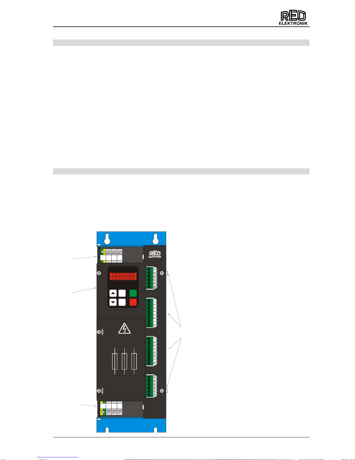
2.0 Construction ........................................................................................................................................... 3
3.0 Functions................................................................................................................................................ 4
3.1 Modes ................................................................................................................................................. 4
3.2 Regulation mode................................................................................................................................. 5
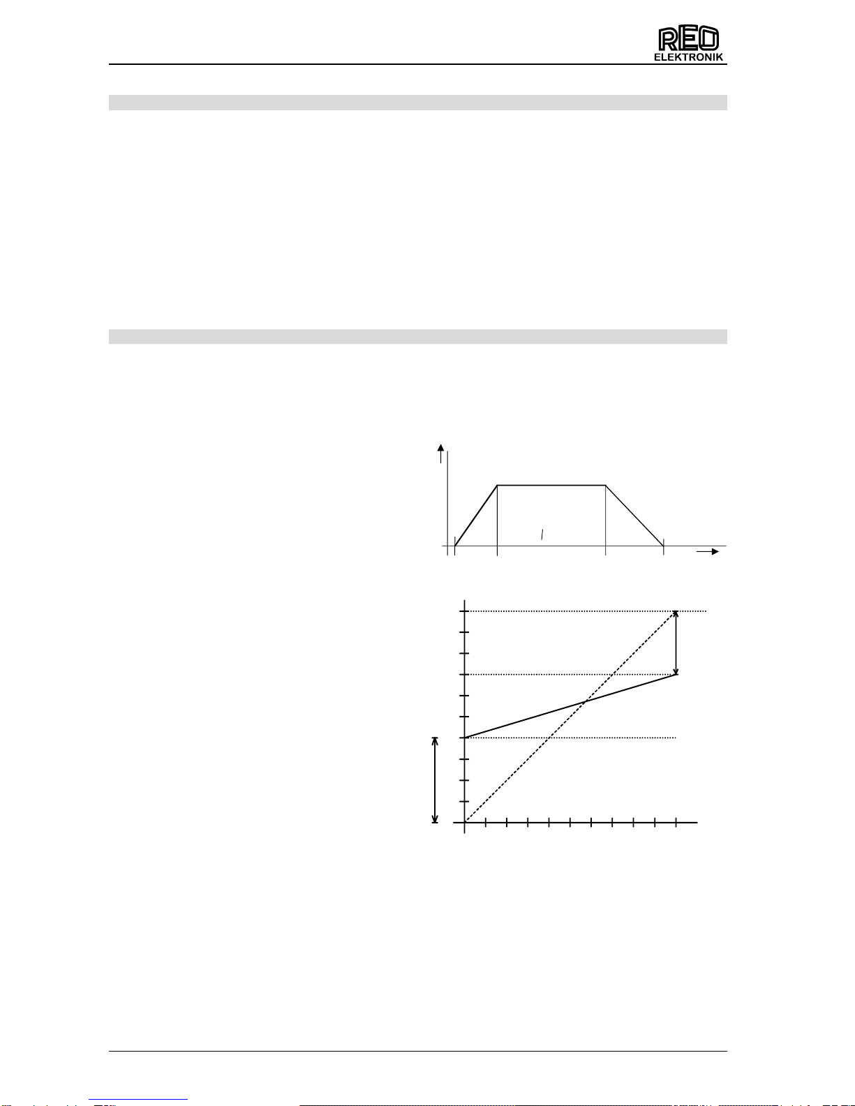
3.3 Set point.............................................................................................................................................. 5
3.4 Feedback ............................................................................................................................................ 6
3.5 Control functions................................................................................................................................. 6
4.0 Technical Data........................................................................................................................................ 7
4.1 Limited the output voltage by using line input from 230V or 240V..................................................... 7
5.0 Declaration of Conformity....................................................................................................................... 7
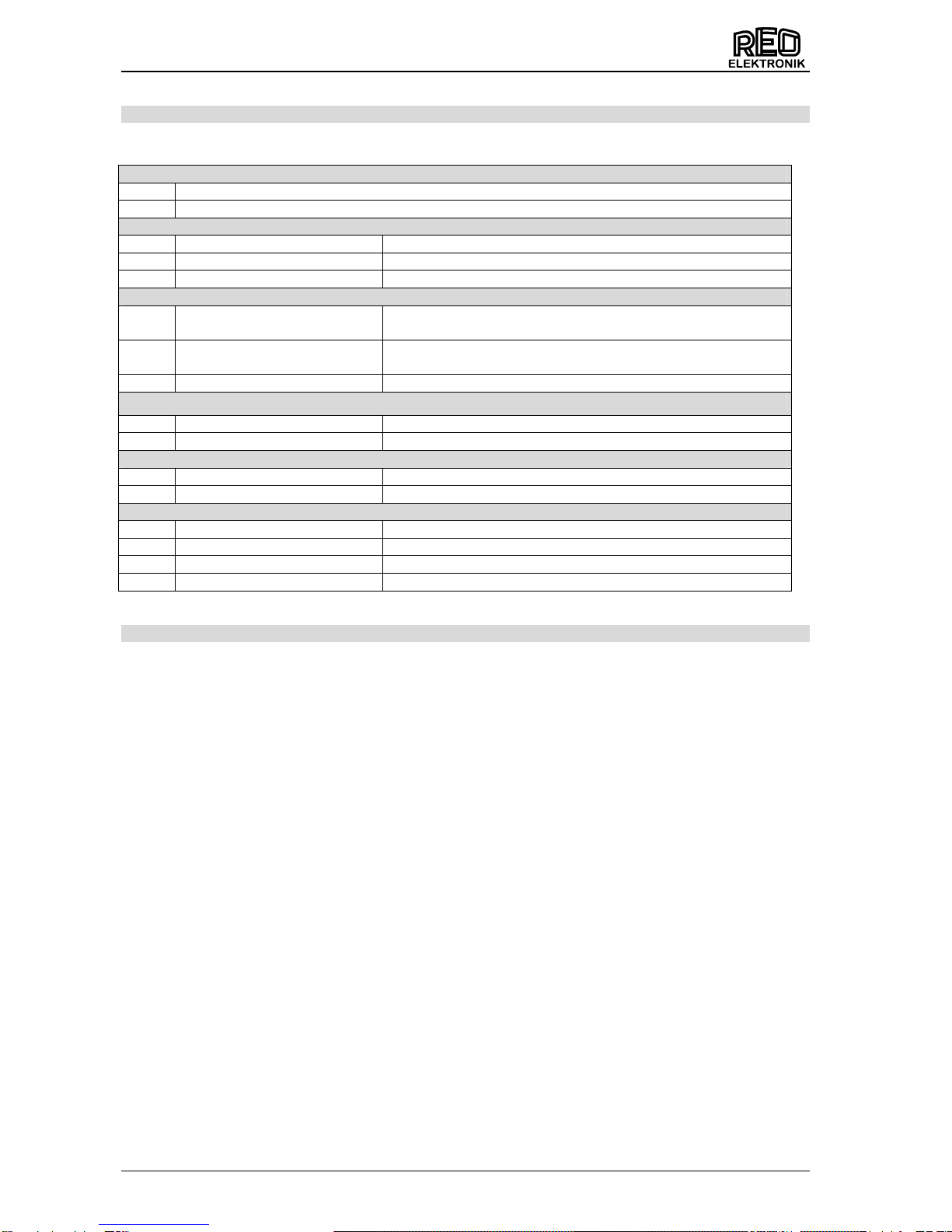
6.0 Ordering codes....................................................................................................................................... 8
7.0 Operation................................................................................................................................................ 9
7.1 Adjustment.......................................................................................................................................... 9
7.2 Adjustment Procedure ........................................................................................................................ 9
7.3 Indications on display........................................................................................................................ 10
7.4 Error Messages................................................................................................................................. 10
8.0 Settings................................................................................................................................................. 11
9.0 Setting up instructions.......................................................................................................................... 12
9.1 Internal set point ............................................................................................................................... 12
9.2 Unit configuration.............................................................................................................................. 12
9.2.1 Service menu................................................................................................................................. 13
9.2.2 Display effective values measured inside unit............................................................................... 13
9.3 Setting Up Procedures...................................................................................................................... 14
9.4 Select Interface................................................................................................................................. 14
9.5 Save current settings........................................................................................................................ 15
9.6 Restore parameter settings .............................................................................................................. 15
9.7 Software version............................................................................................................................... 15
9.8 Hide parameter menus ..................................................................................................................... 15
10.0 Connection diagram ........................................................................................................................... 16
10.1 Connection details .......................................................................................................................... 17
11.0 Dimensions......................................................................................................................................... 18
12.0 Putting into service............................................................................................................................. 22
12.1 Preliminaries................................................................................................................................... 22
12.2 Measurements and Settings........................................................................................................... 22
12.3 Putting into service without a proper load....................................................................................... 22
13.0 Installation of Thyristor Control Units ................................................................................................. 23
13.1 Fuses .............................................................................................................................................. 23
13.2 Incoming breaker............................................................................................................................ 23
13.3 Output Breaker................................................................................................................................ 23
13.4 Installation and climatic Conditions................................................................................................. 23
13.5 Signal cables................................................................................................................................... 23
14.0 Interference prevention....................................................................................................................... 24
14.1 Earthing........................................................................................................................................... 24
14.2 Control cables................................................................................................................................. 24
14.3 Interference protection of other external components and equipment........................................... 24
15.0 Engineering notes............................................................................................................................... 25

REOTRON MDW 700
Operating instructions
2
Technical Information for the User
This description contains the necessary information for the correct application of the product described
below. It is intended for use by technically qualified personal.
Qualified personnel are persons who, because of their training, experience and position as well as their
knowledge of appropriate standards, regulations, health and safety requirements and working conditions,
are authorised to be responsible for the safety of the equipment, at all times, whilst carrying out their nor-
mal duties and are therefore aware of, and can report, possible hazards (Definition of specialist according
to IEC 364).
Safety Instructions
The following instructions are provided for the personal safety of operators and also for the protection of
the described product and connected equipment.
Warning!
Hazardous Voltage
Failure to observe can kill, cause serious injury or damage
•Isolate from mains before installation or dismantling work, as well as for fuse changes or post
installation modifications.
•Observe the prescribed accident prevention and safety rules for the specific application.
•Before putting into operation check if the rated voltage for the unit conforms with the local
supply voltage.
•Emergency stop devices must be provided for all applications. Operation of the emergency
stop must inhibit any further uncontrolled operation.
•Electrical connections must be covered
•Earth bonding must be tested prior to operation
Prescribed Use
The units described herein are electrically powered for use in industrial applications. They are designed
for power adjustment of resistive or inductive loads
These units comply with Directive 2004/108/EC
EMC Directive
!
RoHS
COMPLAINT

REOTRON MDW 700
Operating instructions
3
1.0 General
The range of REOTRON MDW Thyristor Regulators are microprocessor based units for controlling the
power to resistive and inductive loads. In essence the units comprise inverse parallel connected power
semiconductors (thyristors) and the control and regulation electronics. The units have a regulated, AC
output. The inverse parallel connected thyristors operate as contact free, power controllers using the
phase angle control or the full wave principles. In the phase angle control mode the equipment can be
used as a voltage or current regulator and also there is an option for power regulation. The set point value
for the current and voltage can be provided by an external control voltage of 0-10 V, 0(4)-20 mA, DC or a
potentiometer. The lowest set point has priority. The effective value is fed back internally from a voltage
or current transformer. The maximum current limit of the unit cannot be exceeded in all regulation modes,
using phase angle control. Applications with a wide load resistance variation Rcold/Rwarm are possible,
and an overloading of the unit is prevented.
Typical Applications
Industrial Ovens Steam Generators Lighting Installations
Infra Red Emitters (Dryers) Preheating Plants Air Conditioning Plant
Tunnel Heaters Room Heating Equipment Fan Heating Systems
Plastic Moulding Equipment Extruders
2.0 Construction
The REOTRON -MDW 700 thyristor controller is a completely functional, compact, unit. It has been de-
signed for building into an enclosure. All connections for the supply, power output, feedback signals and
the supply for the isolator are made through screw terminals. A touch panel with an LED display and set-
ting up keys is incorporated in the front panel. There are connectors provided for analogue signals and
optional a field bus interface. Inside the unit there is a printed circuit, control card and a power card, com-
prising the semiconductors, firing and regulating circuits and the system power supply.
Overview
Display
Output
Control-
terminals
Input
* MDW 25 A
27
28
2625
24 23 22 21
DO NOT USE
WITHOUT COVER
REOTRON
MDW
www.reo.de
F I
0P
FOR CONTINUED FIRE
PROTECTION REPLACE
ONLY WITH SPECIFIED
TYPE AND RATED FUSE
DISCONNECT POWER
INPUT BEFORE
REPLACING FUSE

REOTRON MDW 700
Operating instructions
4
3.0 Functions
Features:
Mode:
1. Phase angle control
2. Full wave principle
Regulation mode:
1. Current regulation RMS
2. Voltage regulation RMS
3. Power regulation Real power
Set point inputs:
1. Voltage or Power Potentiometer 10 kR, 0...+10 V, 0(4)...20 mA,
internal Keypad
2. Current
Potentiometer 10 kR, 0...+10 V, 0(4)...20 mA,
internal Keypad
Option interface Set point via interface
Feedback monitoring:
1. Voltage or Power Voltage 0...+10 V, DC correspond 0...100% RMS
2. Current Current 0...+10 V, DC correspond 0...100% RMS
Status
Enable (ON/OFF) Contact or 24 V, DC
Fault relay Change over contact
Interface: Option
Serial RS 232
Fieldbus Profibus-DP
Fieldbus CAN-Bus
Fieldbus DeviceNet
3.1 Modes
Phase angle control
In the phase angle control mode the mains voltage half waves are more or less cut in function of the giv-
en set point.
This mode of operation is suitable for resistive, inductive and resistive-inductive loads.
The benefits with this mode of operation are the continuous adjustment, the fine dosing and the high
regulating dynamics. A dynamic current limitation is possible only with this mode of operation.
Full wave control
In the full wave principle mode of operation, always full sinus waves are switched in function of the set
point. In this operating mode almost no harmonics are produced, however, the dynamic regulation is not
possible. This mode of operation is suitable in particular for loads with high thermal inertia.

REOTRON MDW 700
Operating instructions
5
3.2 Regulation mode
The REOTRON MDW Thyristor Regulator range include 3 regulators, ie. voltage, current and power
regulator. All the regulators always work in combination, ie. with voltage regulation for example, the cur-
rent regulation operates like a cascade control and limits the output current in case of overload on the
rated current. In case of current regulation mode, the maximum voltage limit can be prescribed over the
voltage set point. With power regulation, the current limit is also effective as cascade.
In case both the voltage and current regulation are used, the set point of the power regulator must be set
to 100 % (over display, in menu „C 002“, parameter „P“).
Voltage regulation
Microprocessor controller with PI Characteristics; the P portion is adjustable externally by using the key-
Pad. The units maximum voltage output is factory set to the rated voltage (for 100% set point).
Parameter setting
Parameter Code Setting
Output power „P.“ C 020 100%
Set point current „I.“ Display
or Set point current connection 7 u. 8 C 020
100%, or smaller
bridge = 100%
Current regulation
Microprocessor controller with PI Characteristics; the P portion is adjustable externally by using the Key-
Pad. The units maximum output current (Rated Current) is factory set.
Parameter setting
Parameter Code Settings
Output power „P.“ C 020 100%
Set point voltage „U.“ Display
or Set point current connection 3 u. 4 C 020
100%, or smaller
bridge = 100%
Power regulation
With power regulation, the real power value is controlled. In this case, the input that is normally coordi-
nated to the voltage set point is now used as set point input. This set point input corresponds to 0...100
% of the unit output power. The current set point must be set to 100 % or to the required limit value. Set-
ting over display or link between terminals 7 and 8.
Parameter setting
Parameter Code Settings
Output power „P.“ C 020 0%
Set point voltage „U.“ Display C 020 100%, or smaller
Set point voltage „I.“ Display
or Set point current connection 7 u. 8 C 020
100%, or smaller
bridge = 100%
Power regulation „E.F.P.“ C 003 1
3.3 Set point
External signals
Two inputs for set points are available
Set point input U, P 0-10V DC, 0(4)…20 mA or Potentiometer 10kΩ
Set point input I 0-10V DC, 0(4)…20 mA or Potentiometer 10kΩ
Set point over display
All set points can be set over the internal Key-Panel

REOTRON MDW 700
Operating instructions
6
3.4 Feedback
Current feedback
The current is measured, in one phase, with an internal current transformer. The internal microprocessor
determines the effective value of the output current and makes adjustments through a PI loop.
Voltage feedback
The effective voltage is measured with an internal Transformer. It is converted in an analogue input stage
and then fed to the internal microprocessor. The effective value is thus determined and applied used for
PI regulation using software.
Using an external feedback signal of 0..5V is also possible. (See connection diagram)
Output monitor
Effective Voltage 0…10 V, DC correspond 0…100 % output voltage or output power.
Effective Current 0…10 V, DC correspond 0…100 % output current
3.5 Control functions
Enable
Run / Stop input.
A control voltage (24V DC) must be applied to terminals 32(+) and 31(-), to enable the unit, or a connec-
tion made between terminals 32 and 33 by using a switch. A permanent link between terminals 32 and 33
is used for operation without an external enable. The firing pulses are inhibited whilst the enable input is
not closed.
Start ramp / Stop ramp
This function reduces surges on the mains supply
when the load is switched on and off.
Set point control (min / max)
The set-point control characteristics can be
adjusted to match the subsequent process
controller or automation system, by setting the
lower and upper values
Status / Ready relay (clamp 41, 42, 43)
For monitoring the actual status, an internal relay can be used. In case of applied input voltage and ena-
bled power output, clamp 42 – 43 closes.
For using this relay as a “READY” signal point “r.b.” in Code “C 003” has to be set to 1. In case of an error
like “LO.PO.”, clamp 42 – 43 opens.
Clamp assignment: 41 normally close (NC)
42 change-over contact (CO)
43 normally open (NO)
run-up run-down
Output
U,I,P
Time
010 20 30 40 50 60 70 80 90 100[%]
10
20
30
40
50
60
70
80
90
100
[%]
Output-
voltage
Set point
Umin
Umax
adjustment range
Set point
0...100%

REOTRON MDW 700
Operating instructions
7
Failure relay (clamp 44, 45, 46)
In case of an error (for example “Error Hot”) the contact 45 – 46 closes.
Clamp assignment: 44 normally close (NC)
45 change-over contact (CO)
46 normally open (NO)
4.0 Technical Data
Type Input voltage [V] Output voltage [V] Output current[A]
MDW 700-10/230 - 400
230 – 400 V +/-10% 50/60Hz
Ue – 3 V
0…10
MDW 700-25/230 – 400 0...25
MDW 700-50/230 - 400 0…50
MDW 700-80/230 - 400 0…80
MDW 700-110/230 - 400 0…110
MDW 700-150/230 - 400 0…150
MDW 700-200/230 - 400 0…200
MDW 700-300/230 – 400 0...300
MDW WK 700-115/230 - 400 0…115
MDW WK 700-160/230 - 400 0…160
MDW WK 700-250/230 - 400 0…250
MDW WK 700-350/230 - 400 0…350
MDW WK 700-450/230 - 400 0…450
MDW WK 700-600/230 - 400 0…600
Load R / RL, Transformer Load max. Induction 1,45 Tesla
Set point Inputs
current
voltage or power
0...+10 V 22 kR
0(4)...20 mA 100 R
Potentiometer 10 KR, internal Display
External feedback U 0...+/-5 V 22 kR
External feedback I 0...+/-5 V 22 kR
Feedback monitor / U or P 0...+10 V, DC 5 mA
Feedback monitor I 0...+10 V, DC 5 mA
Enable Contact 5 mA or 24 V, DC 5 mA
Faulty relay Change over contact 250 V, 1 A
Protection IP 20
Operating temperature 0... + 45 °C
Liquid temperature WK Type 25 °C Input
Liquid quantity H
2
O, 6 ltr/min
Storing temperature -20...+75 °C
Rel. air humidity 93 % without condensation and surface water coning
Contamination level degree 1 (IEC 664)
Mounting direction Vertical (Connections below)
Mounting height 1000 m, 0,5 % rated current reduction for each additional 100 m
WK = water-cooled
4.1 Limited the output voltage by using line input from 230V or 240V
By using the controller at line input from 230 or 240V you must limited the output voltage under
Code 020 – point „u“. At line= 230V to 57% and at line= 240V to 60%.
5.0 Declaration of Conformity
In order to comply with the EMC requirements, when using phase angle controllers it is necessary to build
in a suitable filter in the line input, e.g. Book-style filter CNW 207 or CNW 107.
(further information in Section 15.0, "Engineering notes")

REOTRON MDW 700
Operating instructions
8
6.0 Ordering codes
Type ID.-No.:
Input voltage
[V] Output current
[A]
REOTRON MDW 700-10/230 – 400 6401.01
230 – 400 3x 10
REOTRON MDW 700-10/230 – 400 Profibus DP 6401.10
230 – 400 3x 10
REOTRON MDW 700-10/230 – 400 RS-232 6401.30
230 – 400 3x 10
REOTRON MDW 700-25/230 – 400 6402.01
230 – 400 3x 25
REOTRON MDW 700-25/230 – 400 Profibus DP 6402.10
230 – 400 3x 25
REOTRON MDW 700-25/230 – 400 RS-232 6402.30
230 – 400 3x 25
REOTRON MDW 700-50/230 – 400 6403.01
230 – 400 3x 50
REOTRON MDW 700-50/230 – 400 Profibus DP 6403.10
230 – 400 3x 50
REOTRON MDW 700-50/230 – 400 RS-232 6403.30
230 – 400 3x 50
REOTRON MDW 700-80/230 – 400 6404.01
230 – 400 3x 80
REOTRON MDW 700-80/230 – 400 Profibus DP 6404.10
230 – 400 3x 80
REOTRON MDW 700-80/230 – 400 RS-232 6404.30
230 – 400 3x 80
REOTRON MDW 700-110/230 – 400 6405.01
230 – 400 3x110
REOTRON MDW 700-110/230 – 400 Profibus DP 6405.10
230 – 400 3x110
REOTRON MDW 700-110/230 – 400 RS-232 6405.30
230 – 400 3x110
REOTRON MDW 700-150/230 – 400 6406.01
230 – 400 3x 150
REOTRON MDW 700-150/230 – 400 Profibus DP 6406.10
230 – 400 3x 150
REOTRON MDW 700-150/230 – 400 RS-232 6406.30
230 – 400 3x 150
REOTRON MDW 700-200/230 – 400 6407.01
230 – 400 3x 200
REOTRON MDW 700-200/230 – 400 Profibus DP 6407.10
230 – 400 3x 200
REOTRON MDW 700-200/230 – 400 RS-232 6407.30
230 – 400 3x 200
REOTRON MDW 700-300/230 – 400 6409.01
230 – 400 3x 300
REOTRON MDW 700-300/230 – 400 Profibus DP 6409.10
230 – 400 3x 300
REOTRON MDW 700-300/230 – 400 RS-232 6409.30
230 – 400 3x 300
REOTRON MDW-
WK
700-115/230 – 400 6337.01
230 – 400 3x 115
REOTRON MDW-
WK
700-115/230 – 400 Profibus DP 6337.10
230 – 400 3x 115
REOTRON MDW-
WK
700-115/230 – 400 RS-232 6337.30
230 – 400 3x 115
REOTRON MDW-
WK
700-160/230 – 400 6338.01
230 – 400 3x 160
REOTRON MDW-
WK
700-160/230 – 400 Profibus DP 6338.10
230 – 400 3x 160
REOTRON MDW-
WK
700-160/230 – 400 RS-232 6338.30
230 – 400 3x 160
REOTRON MDW-
WK
700-250/230 – 400 6339.01
230 – 400 3x 250
REOTRON MDW-
W
K
700-250/230 – 400 Profibus DP 6339.10
230 – 400 3x 250
REOTRON MDW-
WK
700-250/230 – 400 RS-232 6339.30
230 – 400 3x 250
REOTRON MDW-
WK
700-350/230 – 400 6340.01
230 – 400 3x 350
REOTRON MDW-
WK
700-350/230 – 400 Profibus DP 6340.10
230 – 400 3x 350
REOTRON MDW-
WK
700-350/230 – 400 RS-232 6340.30
230 – 400 3x 350
REOTRON MDW-
WK
700-450/230 – 400 6341.01
230 – 400 3x 450
REOTRON MDW-
WK
700-450/230 – 400 Profibus DP 6341.10
230 – 400 3x 450
REOTRON MDW-
WK
700-450/230 – 400 RS-232 6341.30
230 – 400 3x 450
REOTRON MDW-
WK
700-600/230 – 400 Profibus DP 0203.06
230 – 400 3x 600
WK = water-cooled

REOTRON MDW 700
Operating instructions
9
7.0 Operation
The six buttons and a LED display found in the front panel,
are used for operating and setting up the unit. All operating
methods and adjustable parameters can be set up through
this panel.
The “I“ and “O“ buttons are used for switching the unit
ON and OFF, however, these do not provide mains isola-
tion, they simply inhibit the power semiconductors
The “P“, “F“ and “Cursor Buttons“ are used for parameter
adjustment. Parameters are set by using menu controls
which are called up by entering operator codes. A capital
letter is used to indicate the selected function.
The display value can be increased or decreased by units, or
tenths of units, by a short press of the cursor buttons. Holding
the buttons down will cause the display to change in units of
ten.
7.1 Adjustment
To prevent accidental or unauthorized adjustment the adjustment parameters, in the user menus, are
protected. A code must be entered to open the user menus. There are different pass codes for each func-
tion group.
Setting adjustments are automatically saved upon leaving the programming mode or if no button
is pressed for a period of 100 seconds.
7.2 Adjustment Procedure
All setting routines are commenced by pressing the programming button “P“. The following diagram
should clarify the sequence in which keys are pressed:
1. Press the “P“ key.
2. Select the code number with the cursor keys.
3. Press the “P“ key. This displays the first menu point. The required menu point can be found by re-
peatedly pressing the “P“ key (scrolling).
4. The value in the menu point can be changed with the cursor keys.
5. Scroll to the next menu point or to the end of the menu, which returns the display to the set point val-
ue, by pressing the “P“ key. To exit the menu and return back to the normal display quickly, depress
the “P“ key for 5 seconds.
6. To return back to the previous position in the menu, press the “F“ key
I
0
P
F
ON
OFF
DISPLAY
PROGRAMMING
MODE / ENTER
UP
DOWN
BACK
P
Example
F
P
P
P
P
P
PP

REOTRON MDW 700
Operating instructions
10
7.3 Indications on display
During normal running mode ‘run’ is shown in the LED display.
In the programming mode an abbreviation for the corresponding parameter (see setting up instructions)
and the setting values, are displayed. Setting changes are stored upon leaving the programming mode or
after a pause of 100 seconds.
Initialisation Phase. When the supply voltage is connected (Left decimal point
blinks)
Normal Operation
Unit is not enabled
Left decimal point is present. Current regulation is active. The maximum current of
the unit or the regulated current set point value has been reached.
The two upper vertical segments of the first digit illuminate. Peak value limiter.
This is caused by a fault condition on either the load or by the externally generat-
ed effective value, feedback signal. The load impedance is too low, for example,
or the effective value is too high.
The upper horizontal segment of the first digit illuminates. Maximum control limit of
the controller has been reached. The unit has no more regulation range available
and so the output voltage is near to the supply voltage.
Lower horizontal of the first digit illuminates. Maximum power limit has been
reached
Under Voltage, input voltage to too low.
7.4 Error Messages
Over temperature of the power semi-conductors, output is
inhibited. Use `C009` to reset
Overvoltage, input voltage too high, output is inhibited. Use
`C009` to reset
Error messages must be reset in menu `C009`

REOTRON MDW 700
Operating instructions
11
8.0 Settings
The following table contains all the available key settable parameters.
The unit is supplied with factory settings that can be recalled from access code “C210” under FAC. User
codes can be saved under code “C143” and then recalled with code “C210” under USPA.
Parameter: Code
Factory
Default Menu
Code
Set point
–
when internal
set point
is selected only!
•Voltage set point 0...100 % U. 0 % 002
•Current set point 0...100 % I. 0 % 002
•Power set point 0…100 % P. 100 % 002
Configuration
•External set point OFF 0 / I E.S.O 0 003
•4...20 mA (only when E.S.O. = 0) 0 / I 4.20 0 003
•Enable Inverse 0 / I -En. 0 003
•External Voltage set point 0 / I E.F.U. 0 003
•External Current set point 0 / I E.F.I. 0 003
•Power regulation 0 / I E.F.P 0 003
•Full wave control 0 / I F.S.P 0 003
•Ready relay 0 / I r.b 0 003
Parameter
•Minimum Output Voltage (without set point) 0...100 % U. 0 % 020
•Minimum Output Current (without set point) 0...100 % I. 0 % 020
•Minimum Output Power (without set point) 0...100 % P. 100 % 020
•Maximum Output Voltage (Limit) 25...100 % u 100 % 020
•Maximum Output Current (Limit) 25...100 % i 100 % 020
•Maximum Output Power (Limit) 25...100 % p 100 % 020
•Voltage Regulator – P Characteristic 1...100 P.U. 20 020
•Current Regulator - P Characteristic 1...100 P.I. 15 020
•Power Regulator - P Characteristic 1...100 P.P. 15 020
•Soft Start (ramp) 0...60 Sec. /. 0,1 020
•Soft Stop (ramp) 0...60 Sec. \ 0,1 020
Interface
•Interface ON 0 / I S.I.F. 0 017
Service
•Save User Parameter PUSH 143
•Restore Factory Default Settings FAC. 210
•Enable advanced Service mode 0 / I En.S. 0 127
•Display software version 001

REOTRON MDW 700
Operating instructions
12
9.0 Setting up instructions
9.1 Internal set point
Code C 002
9.2 Unit configuration
Code 003
P
P
P
P
P
P
P P
P P
P P
P
P
P
P
P P
P P
U.P.A. = 0 = Regulation mode
U.P.A. = I = control mode
Only in Service Mode
C 127 En.S. = I
E.S.O. = 0 = External Set point
E.S.O. = I = Internal Set point (Keys)
4.20 = 0 = External Set point 0...20 mA / 0...10V
4.20 = I = External Set point 4...20 mA
E.F.U.= 0 = internal feedback voltage
E.F.U. = I = external feedback voltage
Running mode
E.F.P. = 0 = Voltage- / Current regulation
E.F.P. = I = Power regulation set point
F.S.P. = 0 = Phase angle control
F.S.P. = I = Full wave control
r.b. = 0 = Relay = Status function
r.b. = I = Relay = Fault function
-E.n. = 0 = Invert Enable Off
-E.n. = I = Invert Enable On
E.F.I. = 0 = internal feedback current
E.F.I. = I = external feedback current
P
Set point 1, Voltage [%]
Set point 2, Current [%]
F
P
P
P
P
P
Running mode
Set point 3, Power [%]
PP

REOTRON MDW 700
Operating instructions
13
9.2.1 Service menu
Display set-points sent to the unit.
9.2.2 Display effective values measured inside unit
P
Code 050
Display set point voltage [%]
Display set point power [%]
F
P
P
P
Running mode
Display set point current [%]
P
P
Code 051
Display feedback voltage [%]
Display feedback power [%]
F
P
P
P
Running mode
Display feedback current [%]
P

REOTRON MDW 700
Operating instructions
14
9.3 Setting Up Procedures
9.4 Select Interface
Code C 017 Interface (Option)
Communication using the interface is activated by setting parameter “S.I.F.” to “I”. Should there be a need
to run under manual control e.g. for testing, then this parameter should be set to “0”.
P P
P
P
P
P
P
P
P
P
P
P
P
P
P
P
P
P
Code 020
PP
P P
P P
Min ouptput voltage [%]
(without external set point)
Min output current [%]
(without external set point)
Output voltage limit [%]
Umax
Start ramp time [Sec.]
Running mode
Output current limit [%]
Imax
P-Char current regulation
Stop ramp time [Sec.]
Min output power [%]
(without external set point)
P-Char power regulation
Output power limit [%]
Pmax
P-Char voltage regulation
0 = Interface OFF
I = Interface ON
Running mode
P
P
P
P

REOTRON MDW 700
Operating instructions
15
9.5 Save current settings
Code C 143
9.6 Restore parameter settings
Code C 210
9.7 Software version
9.8 Hide parameter menus
Code C 117
If Hd.C. = I all parameter menus are hide. Set Hd.C to "0" again for change parameters.
Save current parameter settings
Running mode
P P
P
P
Restore factory settings
Running mode
Restore user settings
(previously saved in "C 143"
PP
P
P
P
P
Hd.C. = 1= Hide menus
Running mode
P P
P
P
Code 001
Version
Date
Running mode
P P
P
P
P
P

REOTRON MDW 700
Operating instructions
16
10.0 Connection diagram
0(4)...20 mA
0...+10 V
Pot. 10 KR
SETPOINTS
VOLTAGE CURRENT
-+
+10V +10V
-+
-+
-+
24 V
ENABLE
EXTERNAL
FILTER
EXTERNAL
FEEDBACK
0...5V
AC/DC 0...10V
DC 0...10V
DC
U U I
ACTUAL VALUE
OUTPUT RELAY
STATUS
LOAD
I
U
PE L1 L2
L3L2
W
12 3 456 7 8 3332
31
15 16 17 18 11 12 13 14 41 42 43
+
-+
-
V
PE
PE
L1
U
L3
FAILURE
44 45 46
3 AC 230/400 V 50/60 Hz
I
INTERFACE
OPTION
Interface
24 V
DC
+
-
CONTROL LOGIC
3635
34
RELAY
Fan
(MDW 50-300)
U
MDW 700
0...5V
AC/DC
I
(21) (22) (23)
(26) (27) (28)
(24)
(25)
230/240V AC
50/60Hz
(T=Fan test
connector)NTL

REOTRON MDW 700
Operating instructions
17
10.1 Connection details
0...+10 V
0(4)...20 mA
Set point
voltage
Set point
current
Pot. 10 K
123 4 567 8
+10V
+10V
12 3 4 56 7 8
123 4 5 6 7 8
0...+10 V0(4)...20 mA
Set point
voltage
Pot. 10 K
123 4 567 8
+10V
+10V
123 4 567 8
12 3 4 56 7 8
0...+10 V0(4)...20 mA
Set point
current
Pot. 10 K
123 4 567 8
+10V
+10V
123 4 567 8
123 4 567 8
+10V
+10V
+10V
+10V
+10V
+10V
+10V +10V
Voltage and current regulation
Voltage regulation
Current regulation
0...+10 V0(4)...20 mA
Set point
power
Pot. 10 K
123 4 567 8
+10V
+10V
123 4 567 8
123 4 567 8
+10V
+10V
+10V
+10V
Power regulation
If using 4...20 mA signal, set parameter 4.20 = I in Menu " C003"
Actual
output
value Current 0...10 V, DC
Voltage 0...10 V, DC
power
RESERVE
11 13 14 15 16 17 1812
RESERVE
44 45 46
Fault
Relay Internal Relay
41 42 43
Internal Relay
Relay
Reserve

REOTRON MDW 700
Operating instructions
18
255
L1 L2 L3 PE
U V W PE
REOTRON
MDW
PROFIBUS
DP
24V DC
Us
BA
1
ADR.
8
PE
FOR CONTINUED FIRE
PROTECTION REPLACE
ONLY WITH SPECIFIED
TYPE AND RATED FUSE
DISCONNECT POWER
INPUT BEFORE
REPLACING FUSE
REOTRON
MDW
230V
AC
I
0
P
F
210
320
37,5
217,5
8
312
6,5 mm
14,5 mm
6,5 mm
Option
11.0 Dimensions
MDW 700 10 A / 25 A
MDW 700 50A / 80A
Attention connect the fan!
REOTRON
MDW
PROFIBUS
DP
24V DC
Us
BA
1
ADR.
8
PE
41 42 43 44 45 4611 12 13 14 15 16 17 181 2 3 4 5 6 7 831 32 33 34 35 36
FOR CONTINUED FIRE
PROTECTION REPLACE
ONLY WITH SPECIFIED
TYPE AND RATED FUSE
DISCONNECT POWER
INPUT BEFORE
REPLACING FUSE
I
0
P
F
Option
PE L1 L2 L3
PE U V W
290
B
5
285
A
210
5 mm
5 mm
9 mm
15
Type
MDW 25
MDW 10 with Interface 130
110
MDW 10 A
MDW 25 with Interface 160
160
B
70
90
90
90

REOTRON MDW 700
Operating instructions
19
MDW 700 110A / 150A / 200A
Attention connect the fan!
7,5
4
1
5
4
3
0
255
210
231 12
Ø6
Ø6
Ø8,5
Ø8,5
1
6
2
7
3
8
4
9
5
L1 L2 L3
U V W
DO NOT USE
WITHOUT COVER
PROFIBUS
DP
24V DC
Us
BA
1
ADR.
8
PE
REOTRON
MDW
www.reo.de
FOR CONTINUED FIRE
PROTECTION REPLACE
ONLY WITH SPECIFIED
TYPE AND RATED FUSE
DISCONNECT POWER
INPUT BEFORE
REPLACING FUSE
P
F
I
0
PE
230V
AC
Table of contents
Other Reo Elektronik Controllers manuals
Popular Controllers manuals by other brands

Elecbrakes
Elecbrakes ELBC 2000 quick start guide

Parker
Parker Porter MPC Series Installation, programming, & user manual

Steca
Steca Tarom 4545 Installation and operating instructions

Johnson Controls
Johnson Controls VA9104-AGA-1S installation instructions

Belimo
Belimo AFRB24-SR Wiring diagrams

Oase
Oase InScenio EGC Controller Home/Cloud Short manual

Aventics
Aventics Emerson AS3-ACD Series RE-ASSEMBLY INSTRUCTIONS

Siemens
Siemens Simatic S7-1500 manual

Weathermatic
Weathermatic PROLINE PL800 quick start guide

AMX
AMX NetLinx Integrated Controller NI-4100 installation guide

Mitsubishi Electric
Mitsubishi Electric MELSEC FX Series user manual

JEON
JEON DG Series manual