PrehKeyTec MCI TouchKey Instruction manual

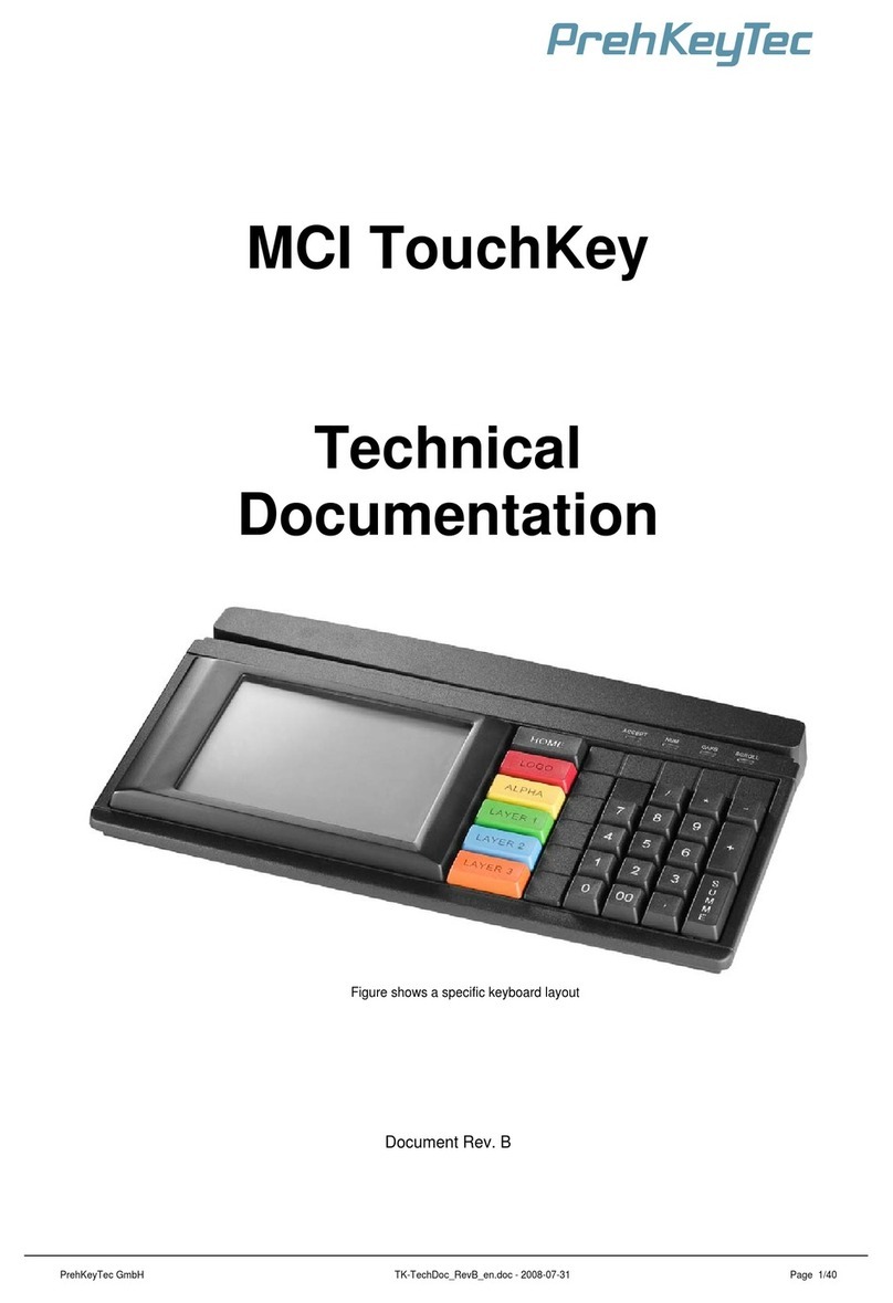
MCI TouchKey
Operating Instructions and Technical Data
Bedienungsanleitung und Technische Daten
Figure shows a specific keyboard layout
Abbildung zeigt spezifisches Tastenlayout
PrehKeyTec GmbH MCI_TouchKey_Manual_V15.doc - 2011-02-09 Page 1/10

EN
1Instruction..................................................................................................................3
1.1 General Notes............................................................................................................................... 3
1.2 Characteristics of the MCI TouchKey ........................................................................................... 3
2Installation .................................................................................................................4
2.1 Contents of package..................................................................................................................... 4
2.2 Installation of the keyboard........................................................................................................... 4
2.2.1 System requirements ....................................................................................................... 4
2.2.2 USB cable installation ...................................................................................................... 4
2.2.3 Cable routing.................................................................................................................... 4
2.2.4 Functional check .............................................................................................................. 4
3Modules......................................................................................................................5
3.1 Magnetic stripe reader (MSR)....................................................................................................... 5
3.2 Keylock (KL).................................................................................................................................. 5
4Software.....................................................................................................................5
4.1 TouchKey Programmer................................................................................................................. 5
4.2 TouchKey Demo Software............................................................................................................ 5
5Additional Help..........................................................................................................5
DE
1Kurzanleitung ............................................................................................................6
1.1 Allgemeine Anwenderhinweise.....................................................................................................6
1.2 Merkmale des MCI TouchKey.......................................................................................................6
2Installation .................................................................................................................7
2.1 Verpackungsinhalt......................................................................................................................... 7
2.2 Installation..................................................................................................................................... 7
2.2.1 Systemvoraussetzungen.................................................................................................. 7
2.2.2 Kabelinstallation USB....................................................................................................... 7
2.2.3 Kabelführung....................................................................................................................7
2.2.4 Funktionskontrolle............................................................................................................ 7
3Module........................................................................................................................8
3.1 Magnetkartenleser (MSR)............................................................................................................. 8
3.2 Schlüsselschalter (KL) .................................................................................................................. 8
4Software.....................................................................................................................8
4.1 TouchKey Programmer................................................................................................................. 8
4.2 TouchKey Demo Software............................................................................................................ 8
5Zusätzliche Hilfe........................................................................................................8
6Appendix / Anhang / Annexe....................................................................................9
6.1 Technical data / Technische Daten / Données techniques .......................................................... 9
6.1.1 Electronics / Elektronik / Electronique.............................................................................. 9
6.1.2 ESD and EMC behaviour / ESD- und EMV-Verhalten / Conformité ESD- EMV ............. 9
6.1.3 Plug assignement / Steckerbelegung / Raccordement électrique................................... 9
6.1.4 Climatic parameters / Klimatische Parameter / Environnement ...................................... 9
6.1.5 Mechanical system / Mechanik / Mécanique ................................................................... 9
6.1.6 Protection class / Schutzart / Indice de protection........................................................... 9
6.1.7 Material and surfaces / Werkstoffe und Oberflächen / Matières et surfaces................... 9
7Declaration of Conformity / Konformitätserklärung / Certificat de conformité..10
FCC Warning Statement..................................................................................................10
PrehKeyTec GmbH MCI_TouchKey_Manual_V15.doc - 2011-02-09 Page 2/10

PrehKeyTec GmbH MCI_TouchKey_Manual_V15.doc - 2011-02-09 Page 3/10
1 Instruction
1.1 General Notes
Congratulations on your purchase of the MCI TouchKey. This product manual is only valid for this keyboard. Should you encounter any
problems or issues configuring this MCI TouchKey please contact your dealer for further advice.
You can find the latest programming and driver software, as well as detailed documentation on our support page:
Hhttp://support.prehkeytec.comH
All PrehKeyTec products undergo a continuous improvement process. For this reason, technical modifications may be made without notice.
We would like to point out that improper handling, storage, actions and/or modifications can lead to malfunctions and damage during use. If
you modify our product as the end user, we are no way responsible for nay warranties or liability, except you are in possession of an
express, written release for your case of operation.
This applies especially to unprofessional repair and maintenance work.
Any claims of damages against PrehKeyTec, regardless of the legal reason, are excluded if we are not responsible for the intent or gross
negligence. The above limitation does not apply to claims for damages resulting from product liability laws.
1.2 Characteristics of the MCI TouchKey
The MCI TouchKey is characterized especially by its ergonomic and compact design. It unites two devices, a keyboard and the TouchKey
with a tactile feedback for the User.
The MCI TouchKey possesses the following characteristics:
•Multiple user defined layouts with Buttons, Graphics and Text
•The Programming is done using the TouchKey Programmer.
•The programming is based on XML files, which can be modified during use.
•There is a programmable keyboard part for fast data entry.
•Layout switching using the TouchKey Buttons or the Keyboard keys.
•Single USB interface and no external power supply needed.
•Use of many TouchKey devices on a single PC.
•Remote programming.
Depending on the housing model, the TouchKey can be built to incorporate the following modules:
•Magnetic Stripe Reader (MSR)
•Key Lock (KL)
The keyboard part of the MCI TouchKey offers 42 programmable key positions. These keys and optional modules MSR/Keylock are
programmed using the WinProgrammer software.
The TouchKey module on the left side is configured by a set of XML definition files – created using the TouchKey Programmer. By default
also here a grid of 42 programmable positions can be assigned for each layout.
All required software is available in the support section of our Website: Hhttp://support.prehkeytec.comH
Also additional documentation can be found here:
•A flash animation helps getting started with the TouchKey Programmer.
•Detailed information about the TouchKey is put together in the "Technical Documentation TouchKey".

PrehKeyTec GmbH MCI_TouchKey_Manual_V15.doc - 2011-02-09 Page 4/10
2 Installation
2.1 Contents of package
Before using your MCI TouchKey, please check whether all the parts shown below are present and show no obvious signs of damage:
- Operating Instructions and Technical Data
- MCI TouchKey
2.2 Installation of the keyboard
2.2.1 System requirements
The MCI TouchKey was developed for computers with USB interface. The following requirements must be on the system for the TouchKey
to function:
•Windows XP or Vista
•.NET Framework 2.0 or higher
•USB Interface with 500 mA current supply and voltage of +5V ± 5%
•Support for Linux OS
2.2.2 USB cable installation
Procedure
Please connect the USB Plug of the TouchKey to a free USB port on your computer. The computer automatically recognizes the MCI
TouchKey device. No special drivers are required.
2.2.3 Cable routing
On delivery, the connection cable is routed on the right side of the device (seen from above). Follow the
described procedure below to move the cable to the left or center:
Lay the keyboard with the keypad facing down on a soft surface. To move the cable outlet to the left,
move the connection cable as shown in Figure 6. Ensure that the keyboard cable is firmly pressed into the
nips provided
2.2.4 Functional check
After starting the computer, all four LEDs on the TouchKey light up briefly. Depending on the status of Num Lock, Caps Lock or Scroll Lock,
the associated LEDs will light up. Your MCI TouchKey is now ready for use.
Fig. 1 Contents of package, figure shows a specific keyboard layout
Fig. 2 USB plug
Nips
Fig. 6 cable nips

PrehKeyTec GmbH MCI_TouchKey_Manual_V15.doc - 2011-02-09 Page 5/10
3 Modules
3.1 Magnetic stripe reader (MSR)
All magnetic cards according to ISO 7810 and 7811 can be read. The magnetic stripe reader records the entire information content of the
magnetic card. A LED signal (green Accept LED) is issued after a successful read procedure.
The magnetic card can be swiped through the reading device in both directions (Figure 7). This provides easy manipulation for both right-
and left-handers
The parameters of the MSR can be set and/or modified using the corresponding PrehKeyTec
programming software.
You can find further information, as well as the associated software, on the Internet under
Hhttp://www.prehkeytec.comH.
Important notice: Please hold the magnetic card near the upper edge during a swipe.
3.2 Keylock (KL)
The optional keylock (Figure 8) module has 5 positions and is supplied with 3 different keys.
All keys can be inserted and removed in both positions 0 and 1
The following switch positions can be set with the three keys:
• SUP key: 0 1 2 3 4
• REG key: 0 1
• X key: 0 1 2
By default, the code for the new switch position is transferred to the computer when the key is turned.
The parameters of the keylock can be set and/or modified using the corresponding PrehKeyTec
programming software.
You can find further information, as well as the associated software, in the Internet under
http://www.prehkeytec.com.
4 Software
4.1 TouchKey Programmer
TouchKey Programmer software is used for programming the TouchKey Module. The TouchKey Programmer helps you to:
•Configure the TouchKey
•Create layouts
•Test layouts on the TouchKey
•Create XML files for communicating with the TouchKey
•Administering multiple TouchKey devices
4.2 TouchKey Demo Software
There is a TouchKey Demo package on our website Hhttp://support.prehkeytec.comHwhich demonstrates the functionality of the MCI
TouchKey device. This example consists of a multiple of layouts with buttons, graphics and text. Furthermore it shows how to switch to other
layouts using buttons or keyboard keys on the device.
In order for this Demo Software to function, the appropriate key table for the keyboard section
needs to be downloaded into the device. This can be done using either the WinProgrammer or the
C2K. Further information can be found on the Readme file of the Demo package.
5 Additional Help
The most recent version of the TouchKey Programmer and further information can be found on our website Hhttp://support.prehkeytec.comH
You can reach our technical support department under:
Email: [email protected]
Fax: +49 9776 / 7046-299
Fig. 7 Magnetic stripe reader
Swipe direction
Turning direction
Fig. 8 Keylock

PrehKeyTec GmbH MCI_TouchKey_Manual_V15.doc - 2011-02-09 Page 6/10
DE
1 Kurzanleitung
1.1 Allgemeine Anwenderhinweise
Wir gratulieren Ihnen zum Kauf des MCI TouchKey.
Die vorliegende Bedienungsanleitung gilt ausschließlich für diese Tastatur.
Falls Sie Probleme im Umgang bzw. mit der Konfiguration des MCI TouchKey haben sollten, so wenden Sie sich bitte an Ihren zuständigen
Händler.
Aktuelle Programmier- und Treibersoftware, sowie weiterführende Dokumentation finden Sie auf unserer Support-Seite:
Hhttp://support.prehkeytec.deH
Unsere Produkte unterliegen einem kontinuierlichen Verbesserungsprozess. Aus diesem Grund behalten wir uns technische Änderungen
vor.
Wir weisen darauf hin, dass unsachgemäße Behandlung, Lagerung, Einflussnahme und/oder Modifikation im Einsatz zu Störungen und
Schäden führen kann.
Sofern Sie unsere Produkte anwenderseitig verändern, übernehmen wir keinerlei Gewährleistung oder Haftung, es sei denn, es liegt Ihnen
von uns eine ausdrückliche, schriftliche Freigabe für Ihren Einsatzfall vor. Dies gilt insbesondere auch für unfachmännische Reparatur- und
Wartungsarbeiten.
Etwaige Schadensersatzansprüche gegen die PrehKeyTec GmbH - gleich aus welchem Rechtsgrund - sind ausgeschlossen, soweit uns
nicht Vorsatz oder grobe Fahrlässigkeit trifft. Obige Beschränkung gilt nicht für Schadensersatzansprüche aus dem Produkthaftungsgesetz.
1.2 Merkmale des MCI TouchKey
Das MCI TouchKey zeichnet sich besonders durch sein ergonomisches und kompaktes Design aus. Es vereint zwei Geräte, eine Tastatur
und das TouchKey mit taktilem Feedback für den Benutzer.
Folgende Merkmale zeichnen das MCI TouchKey aus:
•Beliebige Anzahl benutzerdefinierter Layouts mit Buttons, Grafiken und Texten.
•Die Programmierung erfolgt mit dem TouchKey-Programmer.
•Basierend auf XML-Dateien - kann also recht einfach zur Laufzeit verändert werden.
•Tastaturbereich mit frei programmierbaren Vollhub-Tasten für schnelle Dateneingabe.
•Umschalten der Layouts durch TouchKey-Buttons oder den Tastaturbereich.
•Nur ein USB Anschluss, keine externe Spannungsversorgung notwendig.
•Betrieb mehrerer TouchKeys an einem PC möglich.
•Programmierung des TouchKey kann fernwartbar erfolgen.
Je nach Gehäuseausführung kann das MCI TouchKey werksseitig mit weiteren Modulen ausgestattet werden:
•Magnetkartenleser (MSR)
•Schlüsselschalter (KL)
Im Tastaturbereich verfügt das MCI TouchKey über 42 frei programmierbare Positionen. Diese Tasten und optional integrierte Module
MSR/Schlüsselschalter werden wie gewohnt mit dem WinProgrammer konfiguriert.
Das TouchKey-Modul auf der linken Seite wird über einen Satz von XML-Dateien konfiguriert und gesteuert. Mit dem TouchKey-
Programmer wird diese Konfiguration erstellt, wobei standardmäßig ebenfalls 42 Rasterpositionen je Layout möglich sind.
Alle benötigten Softwarepakete Sie auf unserer Support-Seite unter Hhttp://support.prehkeytec.deH.
Dort finden Sie auch weiterführende Dokumentation:
•Eine Flash-Animation erläutert die ersten Schritte mit dem TouchKey-Programmer.
•Eine umfassende Anleitung zum TouchKey finden Sie in der "Technischen Dokumentation TouchKey".

PrehKeyTec GmbH MCI_TouchKey_Manual_V15.doc - 2011-02-09 Page 7/10
2
Klemmstellen
Bild 3 Kabelklemmstellen
2 Installation
2.1 Verpackungsinhalt
Bitte überprüfen Sie vor der Inbetriebnahme Ihres TouchKey, ob alle nachfolgend aufgeführten Teile vorhanden und optisch unbeschädigt
sind:
1 Diese Kurzanleitung
2 MCI TouchKey
2.2 Installation
2.2.1 Systemvoraussetzungen
Das TouchKey wurde für den Einsatz an Rechnern mit USB Schnittstelle entwickelt.
Voraussetzungen:
•Rechner mit Betriebssystem Windows XP, Vista
•.NET Framework 2.0 oder höher
•USB Schnittstelle mit 500 mA
•Unterstützung von Linux
2.2.2 Kabelinstallation USB
Verbinden sie den USB-Stecker der Tastatur mit einer freien USB-Buchse des Rechners. Das MCI TouchKey
wird automatisch vom Betriebssystem erkannt. Es sind keine speziellen USB Treiber zu installieren.
2.2.3 Kabelführung Im Auslieferungszustand ist das Anschlußkabel auf der rechten Seite ausgeführt (von oben betrachtet).
Sollte es erforderlich sein, den Kabelauslaß nach links oder mittig zu verlegen, so können Sie dies auf
einfache Weise tun.
Legen Sie die Tastatur mit dem Tastenfeld nach unten auf eine weiche Unterlage. Zur Modifikation auf
Kabelauslaß "links" verlegen Sie nun das Anschlußkabel so, wie in Bild 3 dargestellt. Achten Sie darauf,
dass die Tastaturleitung fest in die vorgesehenen Klemmstellen gedrückt wird.
2.2.4 Funktionskontrolle
Nachdem Sie Ihren Computer eingeschaltet haben, leuchten alle vier LED‘s kurzzeitig auf. Anschließend leuchten je nach Status von Num-
Caps- und ScrollLock die dazugehörigen LED's. Auf dem TouchKey-Modul erscheint je nach Konfiguration der entsprechende
Startbildschirm. Ihr MCI TouchKey ist nun betriebsbereit.
Bild 2 USB-Stecker
Bild 1 Verpackungsinhalt, Abbildung zeigt spezifisches Tastenlayout
1

PrehKeyTec GmbH MCI_TouchKey_Manual_V15.doc - 2011-02-09 Page 8/10
3 Module
3.1 Magnetkartenleser (MSR)
Es können alle Magnetkarten nach ISO 7810 und 7811 gelesen werden. Der Magnetkartenleser erfasst den gesamten Informationsgehalt
der Magnetkarte. Nach einem gültigen Lesevorgang erfolgt ein LED-Signal (Accept-LED grün).
Die Magnetkarte kann in beiden Richtungen durch das Lesegerät gezogen werden (Bild 4).
Hierdurch ist eine einfache Handhabung sowohl für Rechts- als auch für Linkshänder
gewährleistet.
Die Konfiguration der Datenausgabe erfolgt im WinProgrammer. Werksseitig ist der
Magnetkartenleser für die Benutzung über OPOS/JavaPOS vorkonfiguriert.
Wichtiger Hinweis: Beim Durchzug ist die Karte nur im oberen Randbereich zu greifen.
3.2 Schlüsselschalter (KL)
Das Optionsmodul Schlüsselschalter (Bild 5) besitzt 5 Stellungen und wird mit 3 verschiedenen Schlüsseln ausgeliefert.
Alle Schlüssel können sowohl in Position „0“ als auch in Position „1“ gezogen und gesteckt werden.
Mit den drei verschiedenen Schlüsseln lassen sich jeweils die folgenden Schalterstellungen einstellen:
• Schlüssel „SUP“: 0 1 2 3 4
• Schlüssel „REG“: 0 1
• Schlüssel „X“: 0 1 2
Die Konfiguration der Datenausgabe erfolgt im WinProgrammer. Standardmäßig wird jeweils beim Drehen des Schlüssels der Code für die
neue Schalterstellung an den Computer übertragen. Werksseitig ist der Schlüsselschalter für die Benutzung über OPOS/JavaPOS
vorkonfiguriert.
4 Software
4.1 TouchKey Programmer
Ähnlich dem WinProgrammer für die frei programmierbaren PrehKeyTec Tastaturen, gibt es für das TouchKey-Modul den TouchKey
Programmer. Mit dieser Programmiersoftware können Sie:
•Das TouchKey konfigurieren
•Layouts erstellen
•Layouts auf dem TouchKey testen
•XML Dateien für die Kommunikation mit dem TouchKey erzeugen
•Mehrere TouchKeys verwalten
4.2 TouchKey Demo Software
Um den Anwender die Möglichkeiten des TouchKey zu zeigen, steht eine Demo Software zur Verfügung. Das Beispiel beinhaltet
verschiedene Layouts mit Buttons, Grafiken und Texten. Ebenso wird die Möglichkeit gezeigt, durch Betätigung von Buttons auf dem
TouchKey oder von Tastaturtasten, andere Layouts aufzurufen.
Das Beispiel und weitere Informationen finden Sie im Internet unter Hhttp://www.prehkeytec.deH.
Damit die Demo Software einwandfrei arbeitet, muss eine passende Tastaturbelegung eingespielt sein. Dies geschieht mit dem
WinProgrammer oder C2K. Weitere Informationen in der Readme-Datei des Demo-Pakets.
5 Zusätzliche Hilfe
Aktuelle Versionen unserer Programmiersoftware, sowie weitere Informationen finden Sie im Support-Bereich von Hhttp://www.prehkeytec.deH.
Unseren Kunden-Support erreichen Sie unter:
Fax: +49 9776 / 7046 - 299
Drehrichtung
Bild 5 Schlüsselschalter
Bild 4 Magnetkartenleser
Durchzugsrichtung

PrehKeyTec GmbH MCI_TouchKey_Manual_V15.doc - 2011-02-09 Page 9/10
6 Appendix / Anhang / Annexe
6.1 Technical data / Technische Daten / Données techniques
6.1.1 Electronics / Elektronik / Electronique
Power supply: 5VDC ±5%
Power consumption: < 500 mA
Keyboard LEDs: ACCEPT, NUM LOCK, CAPS LOCK, SCROLL LOCK
Interface: USB
LCD TouchKey: FSTN black/white
Backlight TouchKey: LED
Touch panel: 4wire resistive
6.1.2 ESD and EMC behaviour / ESD- und EMV-Verhalten / Conformité ESD- EMV
CE symbol
Unwanted emission EN55022, class B
FCC subpart 15 class A
Immunity to interference immunity against high-frequency electromagnetic fields; penetration test value = 10 V/m
immunity against electrostatic discharge according to EN 50082-1; penetration test value = ±8 kV contact, ±13
kV air
6.1.3 Plug assignement / Steckerbelegung / Raccordement électrique
6.1.4 Climatic parameters / Klimatische Parameter / Environnement
Temperature ranges
Storage/transport -30°C to +50°C
Operation ±0°C to +50°C
Relative humidity 5% to 93%
Air pressure 700hPa to 1060 hPa
Climatic test category 0/050/21 according to DIN-IEC 68, part 1, appendix A
6.1.5 Mechanical system / Mechanik / Mécanique
Keys
Actuating force 0.6 N
Stroke strength 10N, 1 min.
Lifetime >3 x 10⁷operations per contact element (typical value)
Keystroke 3.5 mm
Grid spacing 19 mm
6.1.6 Protection class / Schutzart / Indice de protection
IP 54 according to DIN 40050/IEC 529
Only valid for the keypad in the direction of actuation and LCD from top.
6.1.7 Material and surfaces / Werkstoffe und Oberflächen / Matières et surfaces
Housing ABS
Guide frame polystyrene
Film-integrat. circuit polyester film
Sealing membrane Trevira
Key caps PBT/POM
Contact mat silicone rubber
USB Plug A
1 VCC
2 -DATA
3 +DATA
4 GND
Fig. 12.2 USB plug

PrehKeyTec GmbH MCI_TouchKey_Manual_V15.doc - 2011-02-09 Page 10/10
7 Declaration of Conformity / Konformitätserklärung / Certificat de conformité
This is to certify that all varieties of statements of compliance exist for the MCI family.
Of course, you can request us to send you these if you provide the precise type designation (see the type label on the bottom of the device).
PrehKeyTec GmbH
Scheinbergweg 10
D-97638 Mellrichstadt, Germany
Fax: +49-9776-7046-299
FCC Warning Statement
NOTE: This equipment has been tested and found to comply with the limits for a Class A digital device, pursuant to Part 15 of the FCC
Rules. These limits are designed to provide reasonable protection against harmful interference when the equipment is operated in a
commercial environment. This equipment generates uses and can radiate radio frequency energy, and, if not installed and used in
accordance with the instruction manual, may cause harmful interference to radio communications. Operation of this equipment in a
residential area is likely to cause harmful interference in which case the user will be required to correct the interference at his own expense.
Copyright
© Copyright PrehKeyTec GmbH 2011
Published by PrehKeyTec GmbH.
PrehKeyTec GmbH reserves the right to update/modify the products described in this manual, as well as the manual itself, at any time without prior notice.
These operating instructions may not be copied, edited, transformed into electronic form or translated into other languages without prior written consent by PrehKeyTec GmbH.
Trademarks
The brand and product names mentioned in these operating instructions are trademarks / registered trademarks of the corresponding owner.
Examples:
Microsoft, Windows, Windows 98, Windows 2000, Windows XP, Vista are registered trademarks of Microsoft Corporation
Other manuals for MCI TouchKey
1
Table of contents
Languages:
Other PrehKeyTec Keyboard manuals
