Premier Mounts GB-AVSTOR3 User manual

www.mounts.com | North America 800.368.9700 | International +1-714-632-7100
1321 S. State College Blvd., Fullerton, CA 92831 USA
Installation Guide
GB-AVSTOR3

GB-AVSTOR3
Installation Guide
Included Components:
Required for Installation:
Hand Held DrillLadder 1/8” Drill Bit 1/4” Masonry Drill
Bit
Hammer Screwdriver Pencil 24” T-Bar
Protective Eyewear
Warning Statements
Weight Limit
Maximum Weight:
THE CEILING STRUCTURE MUST BE CAPABLE OF SUPPORTING
AT LEAST FOUR TIMES THE WEIGHT OF THE CEILING BOX. IF NOT,
THE CEILING STRUCTURE MUST BE REINFORCED.
PRIOR TO THE INSTALLATION OF THIS PRODUCT, THE INSTALLATION INSTRUCTIONS MUST BE READ AND
COMPLETELY UNDERSTOOD. KEEP THESE INSTALLATION INSTRUCTIONS IN AN EASILY ACCESSIBLE LOCATION
FOR FUTURE REFERENCE.
PROPER INSTALLATION PROCEDURE BY A QUALIFIED SERVICE TECHNICIAN MUST BE FOLLOWED, AS OUTLINED
IN THESE INSTALLATION INSTRUCTIONS. FAILURE TO DO SO COULD RESULT IN PROPERTY DAMAGE, SERIOUS
PERSONAL INJURY, OR EVEN DEATH.
SAFETY MEASURES MUST BE PRACTICED AT ALL TIMES DURING THE ASSEMBLY OF THIS PRODUCT. USE
PROPER SAFETY EQUIPMENT AND TOOLS FOR THE ASSEMBLY PROCEDURE TO PREVENT PERSONAL INJURY.
PREMIER MOUNTS DOES NOT WARRANT AGAINST DAMAGE CAUSED BY THE USE OF ANY PREMIER MOUNTS
PRODUCT FOR PURPOSES OTHER THAN THOSE FOR WHICH IT WAS DESIGNED OR DAMAGE CAUSED BY
UNAUTHORIZED ATTACHMENTS OR MODIFICATIONS, AND IS NOT RESPONSIBLE FOR ANY DAMAGES, CLAIMS,
DEMANDS, SUITS, ACTIONS OR CAUSES OF ACTION OF WHATEVER KIND RESULTING FROM, ARISING OUT OF OR
IN ANY MANNER RELATING TO ANY SUCH USE, ATTACHMENTS OR MODIFICATIONS.
Atleasttwoqualiedpeopleshouldperformtheassemblyprocedure.Personalinjuryand/orpropertydamagecanresult
fromdroppingormishandlingtheprojector.
This product is intended for indoor use only. Use of this product outdoors could lead to product failure and/or serious
personalinjury.
Donotinstallnearsourcesofhighheat.Donotinstallonastructurethatispronetovibration,movementorchanceof
impact.
50 lbs.
Ceiling Box Key
M5 X 8mm Phillips
Head Screw
Zip Ties 1/4” x 3” Eye Lag Screws M6 x 2.4” Eye Anchor Bolts
Equipment Mounting Tray
x1 x2
x6
x1
x12 x4 x4
x1
QUICK LOCK CABLE KIT
Page 2

www.mounts.com | North America 800.368.9700 | International +1-714-632-7100
Installation Guide
GB-AVSTOR3
1
2
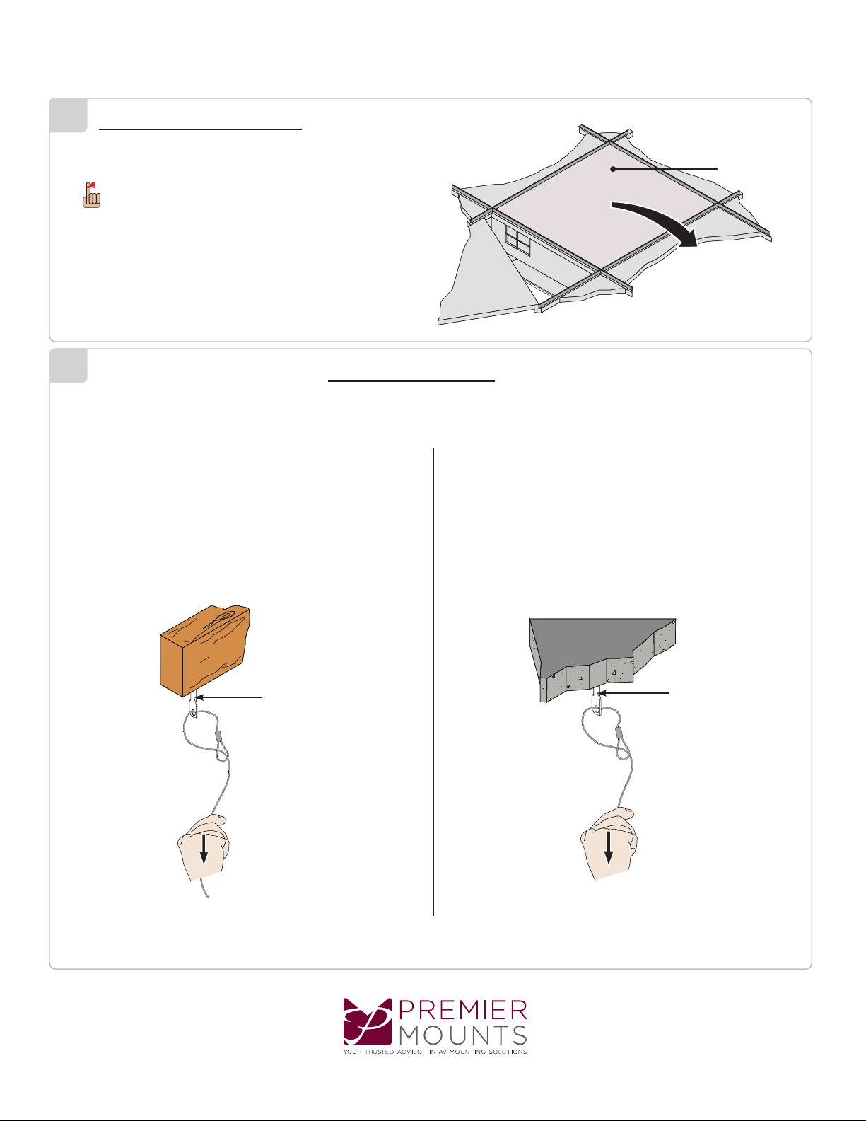
1) Unlock and swing open the lid.
2) Push the lid in and away from the metal hinges
3)Pushthelidtowardtheclosestedgeoftheceilingbox.
4)Pullthelidcarefullyoutfromtheceilingbox.
Lid Removal
Removing the Electrical Knockouts (Optional)
Figure 2
Figure 1
Detach the knockout cover after
removing its screws.
1- and 2-gang electrical knockouts inside the GB-AVSTOR3
1) Remove screws from around the desired electrical knockouts (Figure 1) to
detach their covers.
2) Remove the knockout covers from the top of the GB-AVSTOR3 (Figure 2).
3) Remove the knockouts.
If you have opened a knockout and no longer want to use it, re-attach
itscovertopreventairowintotheceiling.
Installationofthepowermustbedonebyanelectrician.
Page 3
www.mounts.com | North America 800.368.9700 | International +1-714-632-7100
Installation Guide
GB-AVSTOR3
3
4
Ceiling Box Installation
Ceiling Attachment
Wood Stud Ceiling Concrete Ceiling
Ceiling Tile
1) Determine the placement of the GB-AVSTOR3.
2)Removetheceilingtilewheretheceilingboxwillbemounted.
TheceilingboxmustbesecuredusingtheQuickLocksand1/16”braidedcables(supplied).
1) Determine the mounting location.
2)Usea1/8”drillbittopre-drillthemountingholes.
3) Secure the four (4) 1/4” eye lag screws to the wood stud in the ceiling.
4)Runtheopenendofthe1/16”braidedcablethroughthehole
in an eye lag screw.
5) Run the open end through the loop.
6)Pulltheopenenddownuntilthe1/16”braidedcabletightens
around the eye lag screw.
7) Repeat steps 4-6 for the remaining three mounting points.
1) Determine the mounting location.
2)Usea1/4”concretedrillbittodrillthemountingholes.
3)Placetheconcreteeyeanchorboltsintothepre-drilledholes
andgentlytapintoplaceusingarubbermalletorhammer.
4)Runtheopenendand1/16”braidedcablethroughtheholein
aneyeanchorbolt.
5) Run the open end through the loop.
6)Pulltheopenenddownuntilthebraidedcabletightensaround
theeyeanchorbolt
7) Repeat steps 4-6 for the remaining three mounting points.
Store the ceiling tile in a safe location in the event that it needs to
bereused.
Eye Anchor Bolt
Eye Lag Bolt
Page 4
www.mounts.com | North America 800.368.9700 | International +1-714-632-7100
Installation Guide
GB-AVSTOR3
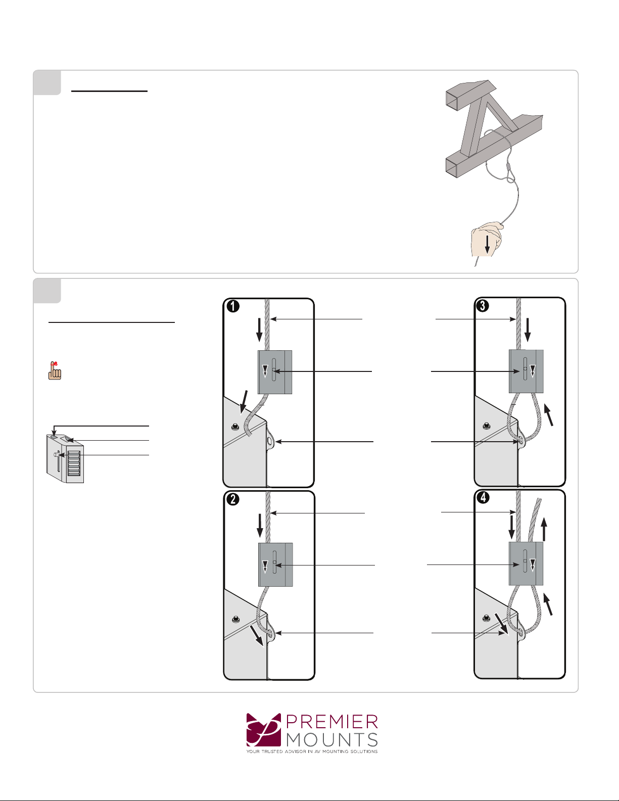
Truss Ceiling
Quick Lock Operation
5
6
1)Loopthebraidedcablearoundthetruss.
2)Runtheopenend1/16”braidedcablethroughtheloop.
3)Pulltheopenenddownuntilthe1/16”braidedcabletightensaroundthetruss.
4) Repeat steps 1-3 for the remaining three mounting points.
Pleasefollowthestepsbelowinnumerical
order 1, 2, 3, and 4 to correctly install the Quick
LockCableKit.
To Release or relieve tension on the 1/16”
braidedcable,slidethereleasepinto
disengage.
Mounting Hole
Release Pin
1/16”BraidedCable
Mounting Hole
Release Pin
1/16”BraidedCable
CableOutput
CableInput
Release Pin
Page 5
www.mounts.com | North America 800.368.9700 | International +1-714-632-7100
Installation Guide
GB-AVSTOR3
7
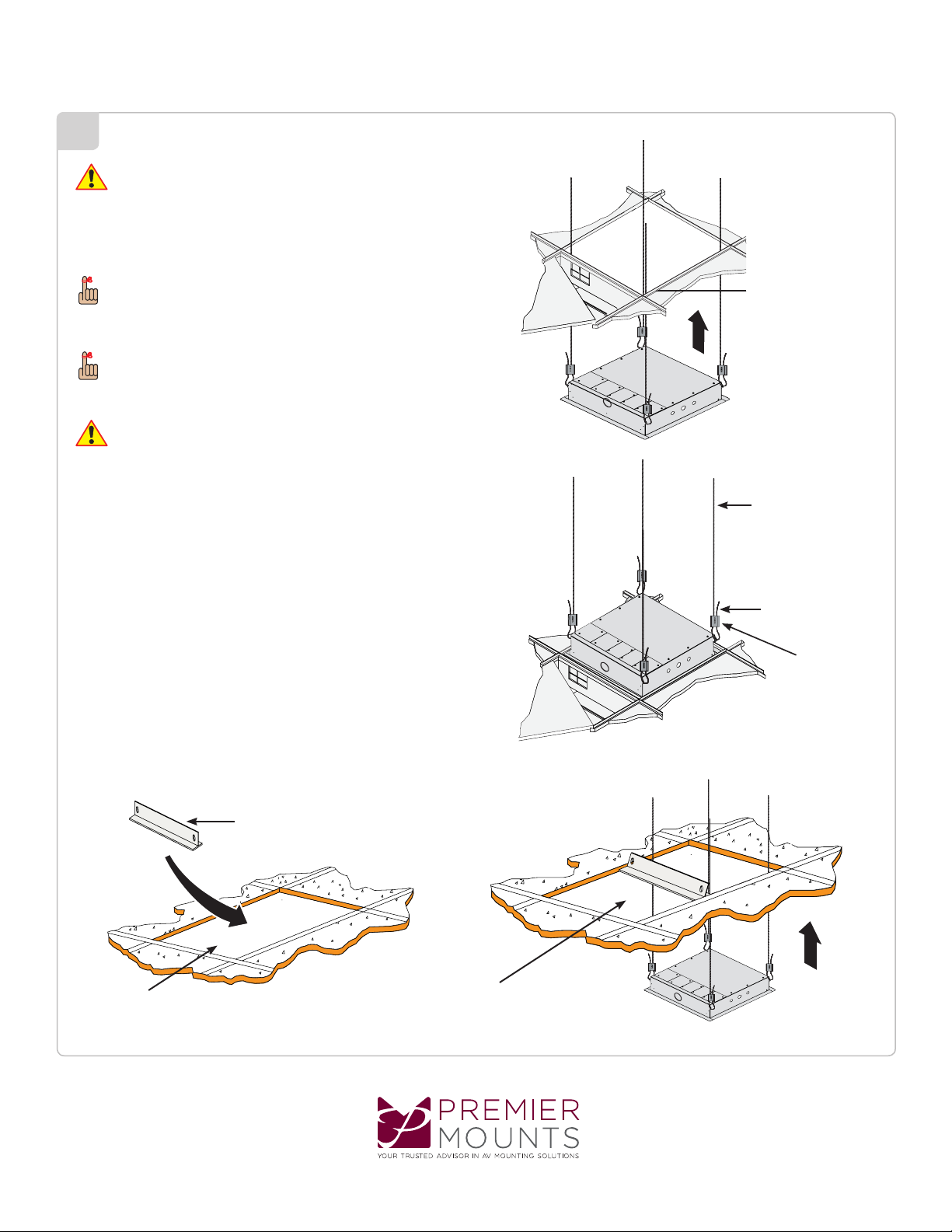
Ceiling
Framework
24” T-Bar Frame
24” x 48” Ceiling Tile
Opening
The replacement 2’ x 2’
ceiling tile goes here.
Figure 3 Figure 4
Figure 2
Figure 1
Quick Lock
6” Excess 1/16”
BraidedCable
1/16”BraidedCableTo
Ceiling Attachment
Ceiling Framework
Itisrecommendedthatthefollowingstepsbeperformedbytwopeople.
Whenadjustingthetensionoftheweight-bearingsideoftheQuickLock,
the1/16”braidedcablemustbepulledthroughtheQuickLockuntilthe
desired tension is attained.
Oncethetensionhasbeenadjusted,besurethatthereaminimumof
6”ofexcess1/16”braidedcableonthenon-weightbearingsideofthe
Quick Lock (Figure 2).
1)Lifttheceilingboxfromtheexposedceilingframeworkuntilthe
ceilingbox’souterliprestsagainstthebottomoftheceiling
framework (Figure 1).
2)Adjustthe1/16”braidedcabletension,butdonotovertighten.
4)Usecablecutterstoremoveanyremaining1/16”braidedcable(optional).
If you installing the GB-AVSTOR3 through a 24” x 48” ceiling tile opening,
attacha24”T-barframe(commerciallyavailable)inthe24”x48”ceilingtile
frameforsupportandplacea2’x2’ceilingtileadjacenttotheGB-AVSTOR3
(Figures 3 and 4).
3)Whenyouhavethedesiredtension,pullthe1/16”braidedcablethrough
the other side of the Quick Lock.
Page 6

www.mounts.com | North America 800.368.9700 | International +1-714-632-7100
Installation Guide
GB-AVSTOR3
8
9
Attaching Equipment to the Tray
Attaching the Mounting Tray to the GB-AVSTOR3
1) Place your electronic components onto the mounting tray.
2)Aligntheelectroniccomponentssothattheweightisdistributedas
evenlyaspossible.
3) Run the zip ties through the mounting slots on the tray, underneath
the mounting tray and up though the mounting slot on the other side
of the electronic component.
4) Tighten the zip tie down and cut off any excess zip tie.
1) Insert four (4) M5 x 8mm Phillips head screws loosely into the outer holes
inside the GB-AVSTOR3 (Figure 1).
2) Place the mounting tray into the middle section of the GB-AVSTOR3 (Figure 2).
3) Hook the mounting tray onto the heads of the M5 x 8mm Phillips head screws on the
GB-AVSTOR3 (Figure 3).
4) Insert two (2) M5 x 8mm Phillips head screws into the middle mounting holes of the
mounting tray.
5) Use a Phillips tip screwdriver to tighten all six (6) screws.
Asareminder,smallscrewsandatwashersmayalsobeusedto
attach electronic components to the grid.
Do not over tighten the mounting screws.
Zip Tie
Mounting Tray
Figure 1
M5 x 8mm Phillips head
Screw
Figure 2 Figure 3
Page 7

www.mounts.com | North America 800.368.9700 | International +1-714-632-7100
Installation Guide
GB-AVSTOR3
10
11
1)Re-attachtheceilingboxlidtotheceilingbox.
2)Swingtheceilingboxlidupintoplace.
1) Hold the lid in place.
2) Use a key (supplied) to lock the lid in place.
3)Donotreleasetheceilingboxliduntilyouaresure
thatthelockhasbeenengagedandthelidissecure.
Page 8

www.mounts.com | North America 800.368.9700 | International +1-714-632-7100
Installation Guide
GB-AVSTOR3
Premier Mounts intends to make this manual accurate and complete. However, Premier Mounts makes no claim that the information contained herein covers all details,
conditions or variations, nor does it provide for every possible contingency in connection with the installation or use of this product. The information contained in this
document is subject to change without notice or obligation of any kind. Premier Mounts makes no representation of warranty, expressed or implied, regarding the
information contained herein. Premier Mounts assumes no responsibility for accuracy, completeness or sufciency of the information contained in this document.
PREMIER MOUNTS
LIMITED LIFETIME WARRANTY
What and Who is Covered by this Limited Lifetime Warranty
Premier Mounts warrants all mounting products to be free from defects in material and workmanship for the
lifetime of the original installation of the product.
What Premier Mounts Will Do
At the sole option of Premier Mounts, Premier Mounts will repair or replace any product or product part that is
defective. If Premier Mounts chooses to replace a defective product or part, a replacement product or part will
be shipped to you at no charge, but you must pay any related labor costs.
What is Not Covered: Limitations
Premier Mounts disclaims any liability for damage to mounts, adapters, displays, projectors, other property,
or personal injury resulting, in whole or in part, from improper installation, modication, use or misuse of its
products.
NOTWITHSTANDING ANYTHING TO THE CONTRARY IN THIS WARRANTY, THIS WARRANTY IS
LIMITED TO FIVE YEARS FROM THE DATE OF PURCHASE IN THE EVENT THAT THE WARRANT-
ED PRODUCT IS COMMERCIALLY RENTED OUT.
Electrical products and components, such as ampliers, speakers, motors, switches remote controls and related
electrical items, are backed by a 3-year warranty.
Premier Mounts disclaims all other warranties, express or implied, including warranties of merchantability and
tness for a particular purpose. Premier Mounts is not responsible for incidental or consequential damages,
including but not limited to, inability to use its products or labor costs for removing and replacing defective
products or parts. Some states do not allow the exclusion or limitation of incidental or consequential damages,
so the above limitation or exclusion may not apply to you.
What Customers Must Do for Warranty Service
If you discover a problem that you think may be covered by the warranty, you must report it in writing to the
address below within thirty (30) days. Proof of purchase (an original sales receipt) from the original consumer
purchaser must accompany all warranty claims. Warranty claims must also include a description of the problem,
the purchaser’s name, address, and telephone number. General inquiries can be addressed to Premier Mounts
Customer Service at 1-800-368-9700. Warranty claims will not be accepted over the phone or by fax.
Premier Mounts
Attn: Warranty Claim
1321 S. State College Blvd.
Fullerton, CA 92831 USA
How State Law Applies
This warranty gives you specic legal rights, and you may also have other rights which vary from state to state.
Page 9 9534-500-001-0X_5
Table of contents
Other Premier Mounts Enclosure manuals


Popular Enclosure manuals by other brands


HP
HP 70001A Installation and Veri cation Manual

Gonnheimer Elektronic
Gonnheimer Elektronic F870S user manual

Thermofilm
Thermofilm HEATSTRIP Max THXDC Series Operation, installation, and maintenance manual

Icop
Icop eBOX-104 installation guide

Coolmax
Coolmax HD-250C-eSATA user manual

Leviton
Leviton Opt-X 5WMNT-01C Instructions for use


