manuals.online logo
Brands
  1. Home
  2. •
  3. Brands
  4. •
  5. Premier
  6. •
  7. Car Receiver
  8. •
  9. Premier SCR-4710TVD User manual

Premier SCR-4710TVD User manual

Other Premier Car Receiver manuals

Premier SCR-0471MP3 User manual

Premier

Premier SCR-0471MP3 User manual

Premier SCR-5381USDR User manual

Premier

Premier SCR-5381USDR User manual

Premier SCR-0934MR User manual

Premier

Premier SCR-0934MR User manual

Premier SCR-5552USID User manual

Premier

Premier SCR-5552USID User manual

Premier SCR-4329DUSD User manual

Premier

Premier SCR-4329DUSD User manual

Premier SCR-2070TFT Operating and maintenance manual

Premier

Premier SCR-2070TFT Operating and maintenance manual

Premier SCR-29MP3 User manual

Premier

Premier SCR-29MP3 User manual

Premier SCR-2067TFT Operating and maintenance manual

Premier

Premier SCR-2067TFT Operating and maintenance manual

Premier SCR-60 User manual

Premier

Premier SCR-60 User manual

Premier SCR-513TFT User manual

Premier

Premier SCR-513TFT User manual

Premier SCR-4606TVD User manual

Premier

Premier SCR-4606TVD User manual

Premier SCR-4709TVD User manual

Premier

Premier SCR-4709TVD User manual

Premier SCR-1510 User manual

Premier

Premier SCR-1510 User manual

Popular Car Receiver manuals by other brands

Linear Series LS5050 Operation and installation manual

Linear Series

Linear Series LS5050 Operation and installation manual

Kenwood KRC-160 instruction manual

Kenwood

Kenwood KRC-160 instruction manual

Sony XR-CA430X Service manual

Sony

Sony XR-CA430X Service manual

T+A Elektroakustik K1 CD-RECEIVER operating instructions

T+A Elektroakustik

T+A Elektroakustik K1 CD-RECEIVER operating instructions

SoundMax SM-CDM1052 instruction manual

SoundMax

SoundMax SM-CDM1052 instruction manual

Xtrons HD107HD user manual

Xtrons

Xtrons HD107HD user manual

Mopar RB3 manual

Mopar

Mopar RB3 manual

Clarion ADDZEST DMZ615 owner's manual

Clarion

Clarion ADDZEST DMZ615 owner's manual

Sony XAV-601BT Specifications

Sony

Sony XAV-601BT Specifications

PIE GM12-POD/S Operation manual

PIE

PIE GM12-POD/S Operation manual

Hyundai H-910H instruction manual

Hyundai

Hyundai H-910H instruction manual

Sony XR-C6100 Service manual

Sony

Sony XR-C6100 Service manual

Sony CDX-L600X - Fm/am Compact Disc Player Installation/connections

Sony

Sony CDX-L600X - Fm/am Compact Disc Player Installation/connections

Motorola VWA63 Service manual

Motorola

Motorola VWA63 Service manual

Sound Storm STM93R user manual

Sound Storm

Sound Storm STM93R user manual

Nextar D3201 instruction manual

Nextar

Nextar D3201 instruction manual

Alpine CDE-163BT owner's manual

Alpine

Alpine CDE-163BT owner's manual

Kenwood KDC-X303 quick start guide

Kenwood

Kenwood KDC-X303 quick start guide

manuals.online logo
manuals.online logoBrands
  • About & Mission
  • Contact us
  • Privacy Policy
  • Terms and Conditions

Copyright 2025 Manuals.Online. All Rights Reserved.

DEAR CUSTOMER
In order to achieve the best performance of your product, please read this
instruction manual carefully before using, and keep it for future reference.
If you need extra support, please write to [email protected]
SCR-4710TVD
INSTRUCTION MANUAL
Car Audio/Video System
/MOD MUTE
IR
AUX
REL
MIC PUSH
SEL
VOL+
VOL-
EQ
CH1~6
USB
BND
PAIR
PREMIER CUSTOMER SERVICE
NOTE
This unit may be submitted to changes in specifications, characteristics and/or operation without prior
notice to the user, in order to continue improving and developing its technology.
Venezuela: 0800 ELECTRIC (353-2874)
Panama: 300-5185
Website www.premiermundo.com
E-mail: servicioalcliente@ premiermundo.com
P-1
Class 1 laser product
This car multi-media player is a class 1 laser product. However
This car multi-media player uses a visible/invisible laser beam
which could cause . Hazardous radiation exposure if directed.
Be sure to operate the car multi-media player correctly as
instructed. Use of controls or adjustments or performance of
procedures other than those specified herein may result in
hazardous radiation exposure. Do not open covers and do not
repair yourself. Refer servicing to qualified personnel.
Precaution
P-2
Premier Customer Service...................................................................
Precaution.........................................................................................
Content.............................................................................................
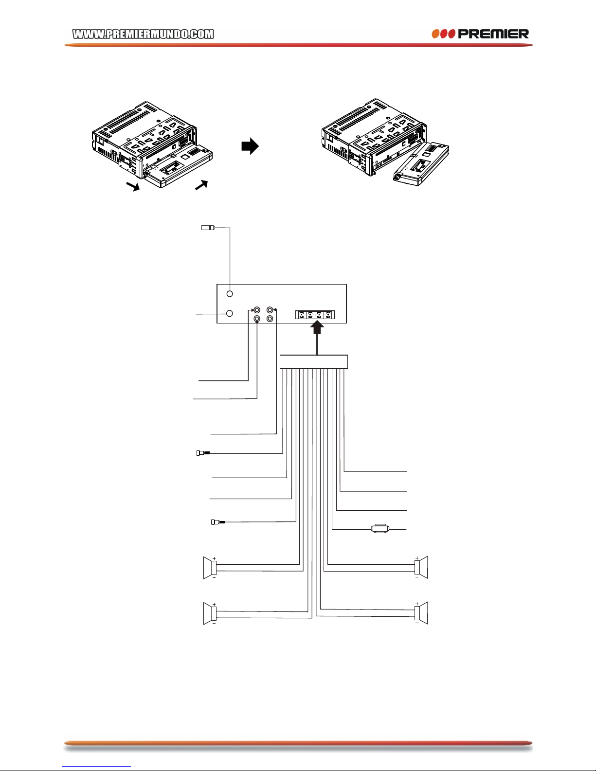
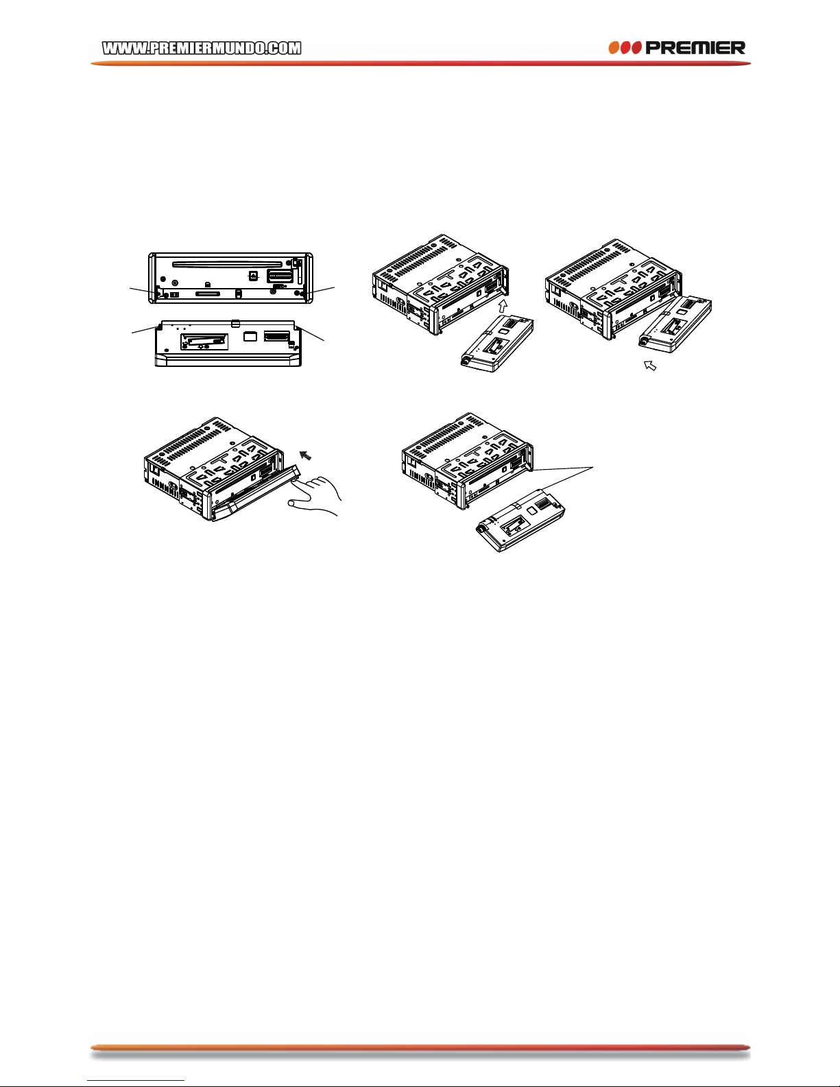
Installation steps................................................................................
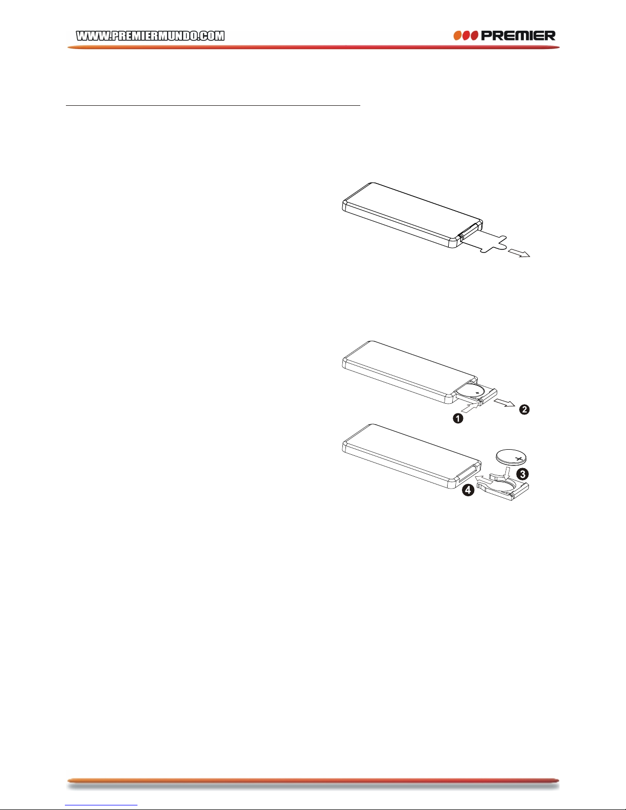
General knowledge about remote control............................................
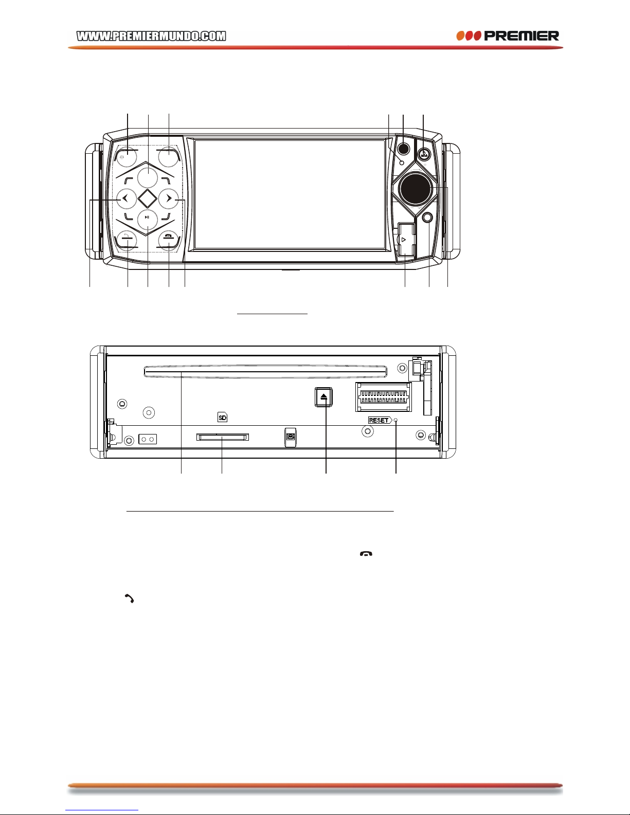
Locations and Names of controls on main unit......................................
Locations and Names of controls on remote control..............................
Same functions in any work source mode............................................
Radio operation................................................................................
TV operation.....................................................................................
BT operation.....................................................................................
Disc/USB/card operation....................................................................
1. Loading or unloading a disc, USB or card........................................
1.1 Loading a disc, USB or card.........................................................
1.2 Unloading a disc, USB or card......................................................
2. Popping up Function Icons-board..................................................
2.1 Function Icons-board of Digital Video/VCD/MPEG4/Image
/MP3/WMA..................................................................................
2.2 CD interface..............................................................................
3. Function of controls on the touch screen/main unit/remote
control........................................................................................
* Region Code...............................................................................
* Parental Control..........................................................................
AV IN operation.................................................................................
Rear View Camera.............................................................................
Troubleshooting................................................................................
Specification....................................................................................
1
2
3
4
8
9
10
11
14
16
17
20
20
20
21
21
21
22
23
32
33
34
35
36
37
Content
P-3
1. Remove the 2 deck screws as right;
2. Mounting Slide Bracket Housing;
1) Remove the PLASTIC FRAME from the chassis ;
2) Insert the 2 KEY PLATES into the grooves at the both sides of the chassis till
they click; then pulling the two KEY PLATES to remove the chassis from the
Slide Bracket Housing ;
3) Mount the Sliding Bracket Housing in the position of car multi-media system and
bend some tabs of Sliding Bracket Housing to fix it.(see Installation Diagram)
3. Connecting all wires:
1) Remove control panel from chassis as follows:
A. Press the REL button to flip down control panel .
INSTALLATION STEPS
KEY PLATE
PLASTIC FRAME
KEY PLATE
If you want to take CHASSIS out of the SLIDE BRACKET HOUSING , first remove
the PLASTIC FRAME of the both sides away, then insert the two KEY PLATES into
left and right sides of chassis as above illustration.
REL button
P-4
B. Hold the left end of the control panel to slide rightwards a little and pull it towards
you to remove it .
2) Connecting all wires according ot the wiring diagram as follows:
1
2
WIRING DIAGRAM
NOTE:
1. Must use 4 ohms impedance of speakers.
2. After connecting parking Line, video on screen of control panel
will be displayed only after
3. Before finishing wiring, do not attach control panel onto chassis.
applying parking brake.
IGNITION SWITCH
RED
WHITE
WHITE/BLACK
GREY
GREY/BLACK
GREEN
GREEN/BLACK
VIOLET
VIOLET/BLACK
YELLOW
CONSTANT 12 VOLTS
BLACK
GROUND(B-)
BLUE
AUTO ANTENNA
FRONT
Lch SPK.
REAR
Lch SPK.
FRONT
Rch SPK.
REAR
Rch SPK.
BROWN
(B-) PARKING BRAKE
PINK
RADIO ANTENNA JACK
(B+) 12V
REAR CAMERA SWITCH
REAR CAMERA INPUT
YELLOW
GREY
SUB WOOFER
AUDIO R OUT (red)
AUDIO L OUT (white)
VIDEO OUTPUT (brown)
FUSE
TV ANTENNA IN
P-5
3) Attach control panel onto chassis.
A. Make the right hollow of control panel aim at the right bulge of chassis, then push
and hold control panel rightwards; at one time, move the left end of control panel
towards chassis to make the left hollow of control panel aim at the left bulge of
chassis and then release holding .
B. Flip control panel up till hearing a click sound to attach onto chassis.
* How to clean panel connector
Frequent detachment will deteriorate panel connectors. To minimize deterioration,
periodically wipe the panel connectors with a clean/soft/dry cloth .
4) Testing it for making sure that it can work properly .
4. Installing main unit according to installation diagram:
1) Insert the chassis of the car multi-media system into the sliding metal housing.
2) Use the metal strap to fix the rear part of chassis.
* Uninstalling main unit:
1) Remove metal strap from main unit;
2) Remove plastic trim frame from main unit;
3) Insert a key plate into left and right side of main unit and draw main unit out of
sliding metal housing.
Bulge
Hollow
Bulge
Hollow
Connector
P-6
Installation diagram
HEX NUT
SPRING WASHER
PLAIN WASHER
TAPPING SCREW
DASH BOARD
METAL MOUNTING
STRAP
CONSOLE
SLIDE BRACKET
HOUSING
FIXING TAB
HEX BOLT
P-7
1. Removing insulating sheet
If
)
)
)
.
)
)
)
.
)
)
using remote control for the first time, you
can see an insulating sheet at the bottom
side of remote control as right.
you must remove the insulating sheet as right.
Otherwise, the remote control is disabled.
2. Replace lithium cell
If the electric energy of lithium cell is weak,
replace it.
1 Press and hold the movable block as direction
indicated by arrow 1 as right, at one time pull
cell holder out of remote control as direction
indicated by arrow 2 as right.
2 Replace the old cell by a new one with (+)
polarity side upward as right.
3 Insert the cell holder into remote control again
as right.
3 Note about using remote control
1 You should face the emitting window of remote control towards the sensor
window of the unit.
2 Operation angle for front panel: About 30 degree
3 The distance between the emitting window of remote control and the sensor
window of the unit : < 5M .
4 Warning for lithium cells of remote control
leakage may cause damage to remote control.1 Cell
2 Do not throw cells into fire, it may cause explosion.
.
3.To avoid risk of accident, keep cells out of reach of children.
GENERAL KNOWLEDGE ABOUT REMOTE CONTROL
P-8
Locations and names of controls on main unit
Front Facet of Chassis after removing Control Panel
14 16 1715
1. POWER/MODE TOUCH BUTTON
2. > TOUCH BUTTON
3. PAIR/ TOUCH BUTTON
4. MUTE TOUCH BUTTON
5. IR SENSOR WINDOW
6. REL BUTTON
7. USB PORT AND COVER
8. AUX IN JACK
9. EQ TOUCH BUTTON
10. BAND/ TOUCH BUTTON
11. < TOUCH BUTTON
12. SEL BUTTON AND VOL KNOB
13. >|| OR CH1~6 TOUCH BUTTON
14. DISC SLOT
15. CARD SLOT
16. EJECT BUTTON
17. RESET BUTTON
18. MICROPHONE
P-9
Control Panel
1
8
23
4 5 6
7
9
1011 1213
/MOD MUTE
IR
AUX
REL
MIC PUSH
SEL
VOL+
VOL-
EQ
CH1~6
USB
BND
PAIR
18