PremierOne MUV-403H Installation and operating instructions
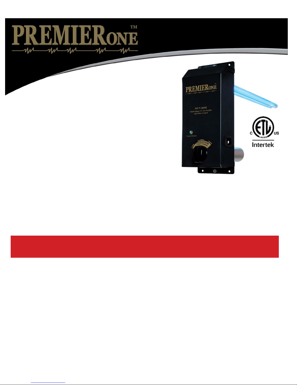
MUV-403H MultiVoltage
Oxidizing UVC System
Installation & Maintenance Instructions
UNPACKING THE UNIT
Each unit is shipped with the 5” lamp installed and the germicidal lamp
placed in a box with protective packaging. Carefully remove lamp from
the tube taking care to not touch the glass portion of the lamp with bare
hands. Oils from the hands can cause “hot spots” which reduce lamp life.
Handle by the end caps or use a soft cloth. If you accidentally touch
a lamp, clean it using the included alcohol cleaning pad or a soft cloth
dampened with rubbing alcohol. The lamp is fragile and proper care
must be taken when removing from packaging.
The following parts are included: • MUV-403H Unit
• Germicidal Twin H Lamp (packed in lamp box)
• Four Sheet Metal Screws
• Installation & maintenance instructions
• 120 VAC Power Cord (PC-120)
• Alcohol pad for cleaning lamps
When installing and using this electrical equipment, basic safety precautions
should always be followed including the following:
1. READ AND FOLLOW ALL INSTRUCTIONS.
2. Minimum living space for this product is 1,200 square feet.
3. Always be sure the unit is unplugged during installation or service procedures.
4. The ultraviolet light produced by the UV lamp is harmful to your eyes. Do not look directly at
the lamp. Should it become necessary to view the lamp, use UV-protected sunglasses.
Lors de l’installation et de l’utilisation de cet équipement, des précautions devront être suivies.
1- Lire et suivre les étapes attentivement.
2- Espace minimum d’une habitation pour ce produit est de 1,200 pi. carrés
3- Assurez vous de toujours débrancher avant l installation ou le service.
4- Ne pas regarder la lampe directement avec les yeux. Si nécessaire de le faire,
veuillez porter les lunettes de soleil contre les rayons U.V.
IMPORTANT: SAFETY INSTRUCTIONS
Important: Instructions de securité
3099107

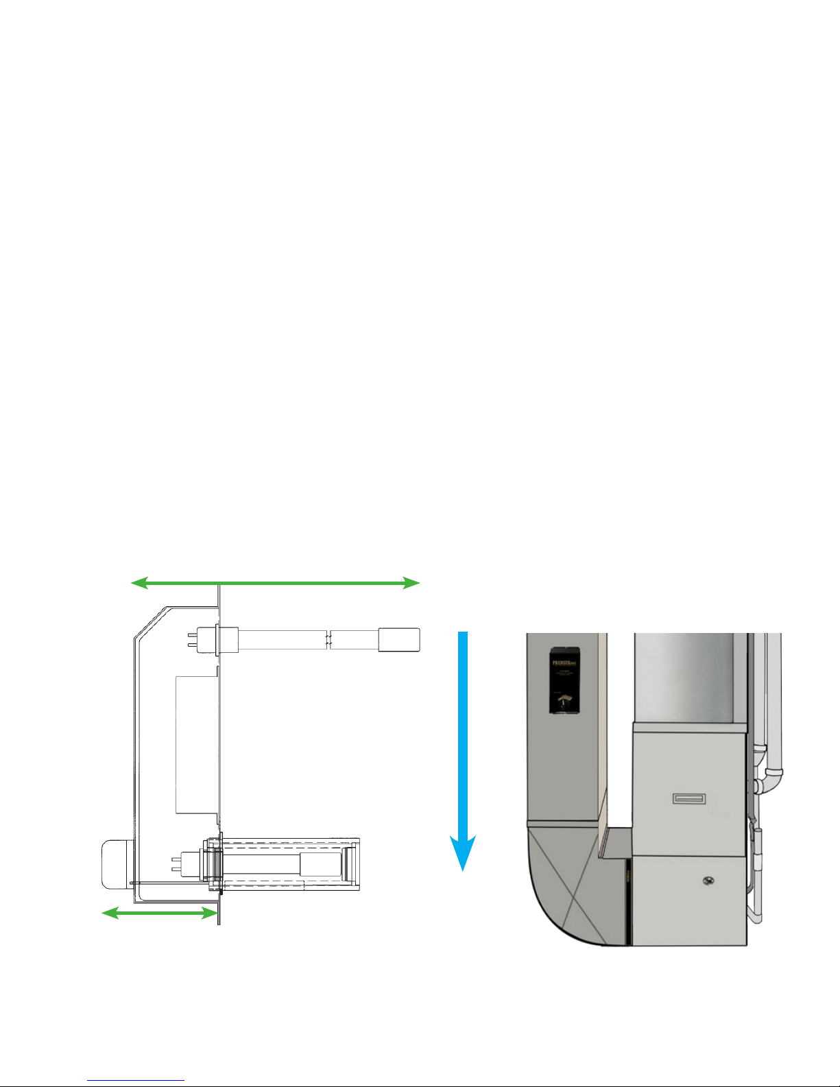
INSTALLATION: Living space, 1,200 square feet minimum.
Best results are achieved when the unit is installed where the HVAC system air temperature is most constant.
Therefore, the preferred installation is on the return side of the furnace. If return side installation is not possible,
install the unit on the supply side. Mount the MUV-403H upstream when installing in combination with a polarized
media air cleaner.
If there is a device that creates ozone in the space such as an ionizing air cleaner, it is recommended the MUV-403H
not be used in the application. For example, an MUV-401H could be substituted. Homes with multiple air handlers:
install one MUV-403H on the main level air handler and an MUV-401H or MUV7-50PS on the other air handler(s).
Do not locate the unit within 20” of plastic materials that will be directly exposed to the UV light, such as wiring,
return side humidier or certain types of air lters. Check with the lter manufacturer to see if their material is UV
resistant. Over time, UV light may degrade some plastics and petroleum based materials.
Do not touch the glass portion of the lamps with bare hands because oils from the hands can cause “hot spots”
which reduce lamp life. Handle either by the end caps or use a soft cloth. If you accidentally touch a lamp, wipe it
off using the included alcohol cleaning pad or a soft cloth dampened with rubbing alcohol.
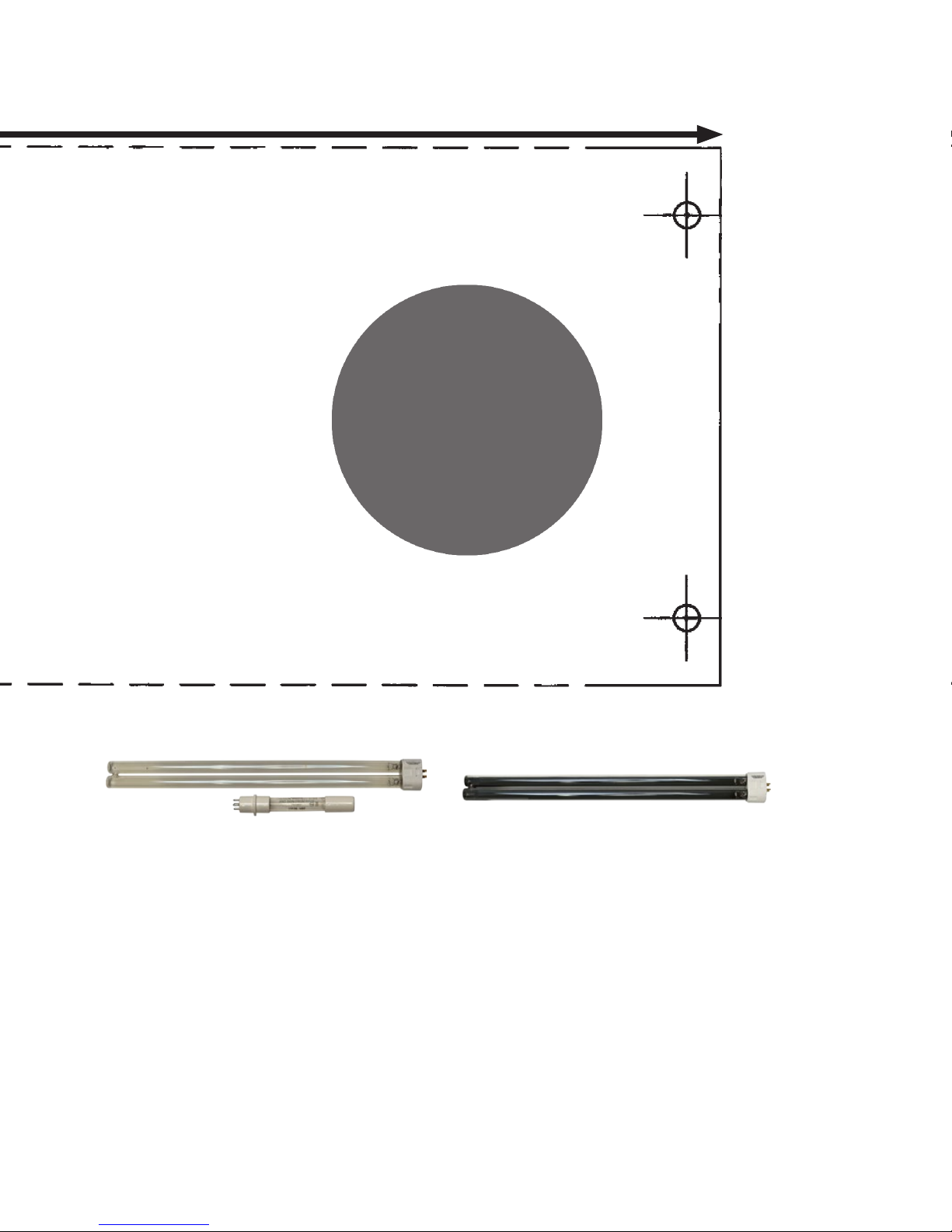
1. Cut out the shaded area of the installation template. (Please see insert.)
2. Center the template on the longitudinal axis of the plenum and attach with tape.
Trace the hole pattern for the unit and mark centers for mounting screws. (Airow direction is marked on the unit.)
3. Cut openings for the unit using a 2” hole saw or tin snips.
4. Remove the cover from the unit by removing the top and bottom retaining nuts using an 11/32 size
nut driver and set aside. Do not remove the oxidation control knob.
(For easier installation rotate control knob to the center position before removing cover.)
5. Attach the unit to the air duct using the four self tapping sheet metal screws provided.
6. Remove the germicidal lamp holder using a 11/32 size nut driver (Figure A).
7. Slide the germicidal lamp into lamp opening.
8. Reinstall the lamp holder and plug lamp into connector.
10. Replace cover and align the oxidizing control knob with adjustment linkage by gently turning the knob until the
linkage clicks into place. Secure cover using the two retaining nuts.
Figure A
Germicidal
lamp holder
16”lamp connector 5”lamp connector
WIRING OPTION 1
The multivoltage ballast is self-adjusting and operates with voltages from 120 - 240 VAC. This unit must
cycle with the furnace blower. Install provided 120 VAC power cord and plug the unit into a 120 VAC outlet
which is interlocked with the furnace blower. If an EAC terminal is available, supply power to the outlet from
the EAC terminal. Connect in accordance with local wiring codes. If there is no EAC terminal, interlock the UV
unit with the furnace blower using an appropriate alternate. After installing verify voltage is operating between
120 - 240 VAC with air handler operating. For 240VAC wiring install 5 amp inline fuses and use optional 240
VAC power cord, Part #PC-240.
WIRING OPTION 2
For hard wiring to 240V systems install 5 amp inline fuses to both legs of power. Then connect the black wire to
L1, white wire to L2, green wire to ground. For 120V wiring install a 5 amp fuse to L1 connect the black wire to
L1, white wire to neutral, green wire to ground. Be sure power cord is secured with a strain relief connector.
Wire the unit in accordance with local wiring codes. After installing, verify voltage is operating between 120
- 240 VAC with air handler operating. Optional power cord with pig tails is available along with a strain relief
connector for hard wiring. Part number PC-HW
SETTING THE ACTIVATED OXYGEN OUTPUT LEVEL
• The air purication process occurs only while air is circulating through the HVAC system.
•
The oxidizing level can be easily adjusted as needed using the “Oxidation Odor Control” knob on the front of unit.
Start with the setting in the normal range. Decrease the setting if an activated oxygen odor is detectable.
If household odors are noticeable after 24 hours, increase the setting
For Technical Support Call (800)982-1840
MUV-403H
Shown installed on a furnace.
For best results,mount the
MUV-403H on the air return.
15 3/4” or 18 3/4”
3 1/2”
AIR STREAM
12” OR 16”
Germicidal UVC Lamp
Box size is
10.75 high
x 4.25 wide.
Protective Shield
5” UVV Lamp
Oxidation
Odor
Control
Adjustment

10 3/4”
4”
UV
Lamp
1. Cut out area of template indicated by the two circles if using a hole saw.
2. Place template on the return path of the HVAC system and trace the hole pattern for the unit
and mark centers for mounting screws. Unit must be oriented so long dimension is parallel
to the direction of the air ow parallel to the direction of the air ow.
3. Cut opening for the unit.
4. Install unit into air duct so that airow matches direction indicated on side of unit using
the four self tapping sheet metal screws provided.
INSTALLATION TEMPLATE MUV-403H
Use a 2” hole saw to cut 2 openings indicated by the gray circles.
Oxidation
Chamber
INSTALLATION TEMPLATE MUV-403H
Use a 2” hole saw to cut 2 openings indicated by the gray circles.
LSK07403H-16/5 UVC16HCP-RF
LAMP KITS FOR MUV-403H
#LSK07403H-16/5 44-Watt UVC/UVV lamp service kit with 16” UV lamp.
#LSK07403H-12/5 36-Watt UVC/UVV lamp service kit with 12” UV lamp.
#UVC16HCP-RF 36-Watt 16” UV lamp with built in reector.
#UVC12HCP-RF 24-Watt 12” UV lamp with built in reector.

TROUBLESHOOTING
• The LED should light when the furnace blower is running.
• Both lamps use the same multivoltage ballast.
If the LED does not light: 1. Check to be sure there is power to the unit.
2. Be sure lamp connectors are fastened securely.
3. If the LED still does not light, replace lamp(s).
4. If still not operating, replace ballast.
Note: Standard off-the-shelf lamps are not compatible with this unit. Use of improper lamps will void warranty.
WARRANTY
All electronic components carry a lifetime warranty to the original homeowner. In addition there is a four-year
warranty from the date of installation for any subsequent owner. We reserve the right to send replacement parts
or to replace the unit at our discretion. This warranty does not cover labor, improper installation or abuse. Use of
any lamp other than a genuine PremierOne lamp designed for this device will void the warranty.
The original lamp is warranted for a period of two years. This warranty does not cover broken lamps due to
shipping, installation or handling. All returns are routed through your wholesaler and must be approved and
accompanied by an RGA#. Please call PremierOne Products, Inc. at 800-982-1840 and we will guide you through
the return procedure.
This warranty gives you specic legal rights and you may also have other rights which vary from state to state.
MAINTENANCE
This maintenance schedule is only a guideline, determined by average conditions. Actual conditions will dictate
the frequency of cleaning and/or replacement of lamps. Do not touch the glass portion of the lamps with bare
hands because oils from the hands can cause “hot spots” which reduce lamp life. Handle either by the end caps or
use a soft cloth. If you accidentally touch a lamp, clean it using a soft cloth dampened with rubbing alcohol.
CLEANING THE LAMPS - Recommended interval: 12 months (Follow the procedure below)
Replacement lamps are available through your HVAC contractor.
REPLACING THE LAMPS - Recommended interval: 24 months. (Follow procedure below excluding #6.)
Note: Standard off-the-shelf lamps are not compatible with this unit. Use of improper lamps will void warranty.
1. Unplug the power cord from the outlet, or disconnect power to the unit.
2.
Remove the cover from the unit by removing the top and bottom retaining nuts using a 11/32 size nut driver. Do
not remove the Oxidation Control knob. (It helps to rotate the control knob to the center position before removing cover.)
3. Unplug the lamp from each lamp connector.
4. Remove lamp holders using a 11/32 size nut driver (Figure A).
5. Remove each lamp by grasping the end cap and extract carefully.
6. Using a soft cloth moistened with rubbing alcohol, wipe down each lamp. If there is a large build-up of dust
particles, you may wish to use a can of air rst. Always handle lamps by end caps.
7. Slide one lamp back into lamp opening. Reinstall lamp holder.
8. Repeat step 7 for second lamp.
9. Plug each lamp into the corresponding lamp connector.
10. Replace cover and align the oxidation control knob with the adjustment linkage by gently turning the knob
until linkage clicks into place. Secure cover using the two retaining nuts.
11. Plug power cord back into outlet, or restore power to unit.
For Technical Support Call (800)982-1840 www.premieroneproducts.com ©2016
Table of contents
Other PremierOne Medical Equipment manuals


Popular Medical Equipment manuals by other brands


Bionet
Bionet BM5VET user manual

B. Braun
B. Braun Aesculap MACS T 011148 Instructions for use/Technical description

ARJO HUNTLEIGH
ARJO HUNTLEIGH Enterprise 5000X Quick reference guide

Smith & Nephew
Smith & Nephew VERSAJET II Quick setup guide

Contec
Contec KT88-3200 manual

Cooper Surgical
Cooper Surgical Prima PSV-2L Directions for use


