Premio MSI ATX TX5 User manual

CHAPTER 1 INTRODUCTION
Chapter 1
INTRODUCTION
The MSI ATX TX5 mainboard is a high-performance personal computer
mainboard. This mainboard supports Intel® Pentium® processor/Pentium®
processorwithMMXTMtechnology, Cyrix®6x86/6x86L/6x86MXprocessor,
and AMD®K5/K6 processor. The mainboard also supports four 32-bit PCI
(Peripheral Component Interconnect) Local Bus standard slots.
The mainboard uses the highly integrated Intel®83430TX chipset to support
the PCI/ISA and Green standards, and to provide the Host/PCI bridge. The
Intel®82430TX chipset integrates all system control functions such as ACPI
(Advanced Configuration and Power Interface). The ACPI provides more
Energy Saving Features for the OSPM(OS Direct Power Management)
function. The Intel®82430TX chipset also improves the IDE transfer rate by
supporting Ultra DMA/33 IDE that transfer data at the rate of 33MB/s.
The mainboard also supports the LM78 and LM75 Hardware Monitor
Controller which are optional functions. The LM78 function includes: CPU
chassis/power fan control, CPU temperature detect and protect, system
voltage detect and chassis intrusion detect. The LM75 function includes:
CPU overheat warning.
1-1

CHAPTER 1 INTRODUCTION
1.1 Mainboard Features
CPU
lSocket 7 supports Intel®Pentium®processor /Pentium®processor w/
MMXTM technolgy.
lTheCyrix®6x86/6x86L/6x86MX andAMD®K5/K6 processorarealso
supported.
Chipset
lIntel®82430TXchipset.
Cache Memory
lSupports 512K pipelined burst cache memory.
lSupports Direct Map Organization and Write-Back cache policy.
Main Memory
lSupports five memory banks using two 72-pin SIMM sockets and three
168-pin DIMM sockets (for unbuffered DIMM).
lUp to 256 Mbytes main memory.
lSupports EDO Hyper Page Mode DRAM, Standard Fast Page mode
DRAM and SDRAM(Synchronous DRAM).
Slots
lFour 32-bit PCI Bus slots (four 32-bit bus master PCI slots + four 16-bit
ISA bus slots). One shared slot can be used as ISA or PCI.
On-Board IDE
lSupports Bus Master and Ultra DMA/33 IDE.
lSupports up to 4 IDE drives.
On-Board Peripherals
lOn-BoardPeripheralsinclude:
- 1 floppy port supports 2 FDD
-2serialports(COMA+COMB)
- 1 parallel port supports ECP or EPP mode
-USBPorts
- IR (reserved)
1-2

CHAPTER 1 INTRODUCTION
1-3
Dimensions
lStandard ATX form factor
l30cm(L)x18.6cm(W)x4layerPCB
lDouble deck I/O connectors, compatibles with Intel®Venus mainboard
Mounting
l6 mounting holes
LM78 System Hardware Monitor(optional)
lCPU fan Rotation Speed Control
lCPU Fan Control/Power Fan Control (the fan will automatically stop when
the system enters suspend mode)
lSystem Voltage Detect
lCPU Overheat Warning (reserved)
lChassis Intrusion Detect(reserved)
lDisplay Actual Current Voltage
Other Features
lPoly Fuse used by keyboard and USB devices
lKeyboard password wake up system(reserved)
lCPU Vcore voltage protect
lMeets ACPI specifications
lPower ON/OFF switch connector on board
lSoftPower-Off
lRing Wake-Up
lAlarmWake-Up

CHAPTER 1 INTRODUCTION
1.2 Parts of the Mainboard
1-4
A
B
C
D
EG
H
J
K
L
N
O
P
F
I
M

CHAPTER 1 INTRODUCTION
1-5
A PS/2 Ports Top: Mouse
Bottom: Keyboard
B USBPorts Top: Port 1
Bottom: Port 2
C COM/LPT Ports Top: Parallel Port
Bottom: Two Serial Ports
D Four 32-Bit PCI SLOTs
E LM78
F Four 16-Bit ISA SLOTs
G Flash BIOS
H Coin Type Battery
I ChassisIntrusion Sensor
J Intel®82371AB (PIIX 4) chipset
K Intel®82489TX chipset
L CPU Socket 7
M LM75
N ATX 20-Pin Power Connector
O Three 168-PIN DIMM SOCKETs
P Two 72-PIN SIMM SOCKETs

CHAPTER 1 INTRODUCTION
1.3 Mainboard Layout
1-6
MS-5158
ISA SLOT
ISA SLOT
ISA SLOT
PCI SLOT 4
PCI SLOT 3
PCI SLOT 2
PCI SLOT 1
DIMM 1
SOCKET 7
ISA SLOT
DIMM 2
DIMM 3
SIMM 1
FDC
BATT
+
SIMM 2
IDE1 BIOS
ATX
Power Supply
FW82371AB
FW82439TX
JGL
JFP
IDE2 JGS
JIR
JP2
JP1
JV1
JBAT
SW1
JFAN 2
JFAN 1
JRMS1
Top: JSMS
Bottom:
JSKBD
Top: Port1
USB
Bottom:
Port2
Top: LPT
Bottom:
COM A
COM B
LM75
(optional)
LM78
(optional)
JP3 JFAN 3
Clock
Generator
Chassis
Intrusion
Sensor
JRMS2
JP15

CHAPTER 2 HARDWARE INSTALLATION
Chapter 2
HARDWARE INSTALLATION
2.1 Central Processing Unit: CPU
The MSI ATX TX5 mainboard operates with Intel®Pentium® processor/
Pentium® processor with MMXTMtechnology, Cyrix®6x86/6x86L/
6x86MX and AMD®K5/K6 processors. It could operate with 2.1V to 3.5V
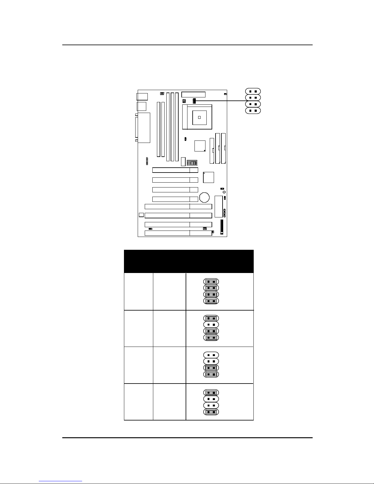
processors. The mainboard provides a 321-pin ZIF Socket 7 for easy CPU
installation, a DIP switch (SW1) to set the proper speed for the CPU and a
Jumper block (JV1) for setting the CPU voltage. The CPU should always
have a cooling fan attached to prevent overheating.
CPU
CPU
2-1
3. Press the lever down to
complete the installation.
2. Locate Pin 1 in the socket
and look for the white dot or
cut edge in the CPU. Match
Pin 1 with the white dot/cut
edge. Then, insert the CPU.
It should insert easily.
OpenLever
Pin1
Sliding
Plate
White dot/
Cut edge
Close
Lever
1. Pull the lever sideways away
from the socket. Then raise
the lever up to a 90-degree
angle.
2.1-1 CPU Installation Procedures

CHAPTER 2 HARDWARE INSTALLATION
4 5 6 Clock
OFF OFF ON 50MHz
ON ON OFF 55MHz
ON OFF OFF 60MHz
OFF OFF OFF 66.8MHz
OFF ON OFF 75MHz
ON ON ON 83MHz
4 5 6 Clock
ON ON ON 50MHz
ON OFF OFF 60MHz
OFF OFF OFF 66.6MHz
OFF ON OFF 75MHz
ON OFF ON 83MHz
SW1 CPU
2.1-2 CPU Core Speed Derivation Procedure
The mainboard uses two kind of Clock generator: ICS9148-04 and IMI643.
These two clock generator have different clock frequency.
1. The DIP Switch SW1 (4, 5, and 6) is used to adjust the CPU clock
frequency.
A. Clock Generator: ICS9148-04
SW1 CPU
B. Clock Generator: IMI643
2-2

CHAPTER 2 HARDWARE INSTALLATION
1 2 3 Core/Bus Ratio
OFF OFF OFF 1.5 /3.5
ON OFF OFF 2
ON ON OFF 2.5
OFF ON OFF 3
ON OFF ON 4
ON ON ON 4.5
2. The DIP Switch SW1 (1, 2, and 3) is used to set the Core/Bus
(Fraction) ratio of the CPU. The actual core speed of the CPU is the
Host Clock Frequency multiplied by the Core/Bus ratio. For example:
If CPU Clock = 66MHz
Core/Bus ratio = 3/2
then CPU core speed = Host Clock x Core/
Bus ratio
= 66MHz x 3/2
= 100MHz
3. The PCI Bus Clock is the CPU Clock Frequency divided by 2.
SW1 CPU
2-3

CHAPTER 2 HARDWARE INSTALLATION
2-4
2.1-3 CPU Voltage Setting: JV1
JV1
VcoreV I/O
3.5 3.5
3.3 3.3
3.3 3.2
3.3 2.9
JV1
1
2
3
4
1
2
3
4
1
2
3
4
1
2
3
4
1
2
3
4

CHAPTER 2 HARDWARE INSTALLATION
VcoreV I/O
3.3 2.8
3.3 2.5
3.3 2.4
3.3 2.3
3.3 2.2
JV1
1
2
3
4
1
2
3
4
1
2
3
4
1
2
3
4
3.3 2.1 1
2
3
4
2-5
1
2
3
4
3.3 2.0 1
2
3
4

CHAPTER 2 HARDWARE INSTALLATION
To adjust the speed and voltage of the CPU, you must know the specifica-
tions of your CPU (always ask the vendor for CPU specifications). This
mainboard uses two different Clock Generator, so before adjusting SW1,
check your clock generator. Then refer to Table 2.1 (Intel®Pentium®
processor/Pentium® processor with MMXTM technology), Table 2.2
(Cyrix®6x86/6x86L/6x86MX processor) and Table 2.3 (AMD®K5/K6
processor) for proper setting.
2.1-4 CPU Speed and Voltage Setting: SW1 & JV1
2-6
SW1
1 2 3 4 5 6
ON DIP ON
OFF
1
2
3
4
JV1
Clock
Generator
ICS9148-04/
IMI643
Note: The table provided can be used by both clock generator. The only
difference with the ICS9148-04 and IMI643 Clock Generator is the
CPU clock frequency of 50, 55, 83 MHz. Since these 3 frequencies
are not supported by the current CPUs, so the jumper settings for
both regulator are the same.

CHAPTER 2 HARDWARE INSTALLATION
Table 2.1 Intel®Processor
90MHz
100MHz
120MHz
133MHz
150MHz
166MHz
200MHz
3.38/3.52
CPU Type CPU SpeedCPU Voltage
SW1VI/O Vcore
2-7
JV1
ON DIP
123 456
ON
OFF
ON DIP
123 456
ON
OFF
ON DIP
123 456
ON
OFF
166MHz
200MHz 3.3 2.8
233MHz
b. Intel®Pentium® Processor with MMXTM Technology
a. Intel®Pentium® Processor
1
2
3
4
1
2
3
4
1
2
3
4
Note: If you encounter a CPU with different voltage, just go to Section
2.1-3 and look for the proper voltage settings.
ON DIP
123 456
ON
OFF
ON DIP
123 456
ON
OFF
ON DIP
123 456
ON
OFF
ON DIP
123 456
ON
OFF
ON DIP
123 456
ON
OFF
ON DIP
123 456
ON
OFF
ON DIP
123 456
ON
OFF

CHAPTER 2 HARDWARE INSTALLATION
3.5
CPU Type CPU SpeedCPU Voltage
SW1
VI/O Vcore
6x86
PR150
6x86
PR166
6x86
PR200
2-8
3.3 2.8
JV1
6x86L
PR166
3.5
1
2
3
4
1
2
3
4
1
2
3
4
6x86L
PR200
ON DIP
123 456
ON
OFF
ON DIP
123 456
ON
OFF
ON DIP
123 456
ON
OFF
3.3 2.8
1
2
3
4
a. Cyrix®6x86/6x86L Processor
Table 2.2 Cyrix®Processor
Cyrix®processor uses PR to rate the speed of their processors based on
Intel®Pentium® processor core speed. For example PR150 (120MHz) has
150MHz core speed of Intel®Pentium® processor but has 120MHz core
speed in Cyrix®processor. Cyrix®processor should always uses a more
powerful fan (ask vendor for proper cooling fan).

CHAPTER 2 HARDWARE INSTALLATION
CPU Type CPU SpeedCPU Voltage
SW1VI/O Vcore
6x86MX
PR166
6x86MX
PR233 3.3 2.9
JV1
6x86MX
PR200
6x86MX
PR266
60 x 2.5
75 x 2.5
66 x 3
75 x 3
b. Cyrix®6x86MX Processor
Note: If you encounter a CPU with different voltage, just go to Section 2.1-3
and look for the proper voltage settings.
2-9
ON DIP
123 456
ON
OFF
ON DIP
123 456
ON
OFF
ON DIP
123 456
ON
OFF
ON DIP
123 456
ON
OFF
ON DIP
123 456
ON
OFF
ON DIP
123 456
ON
OFF
66 x 3.5
66 x 2.5
1
2
3
4

CHAPTER 2 HARDWARE INSTALLATION
Table 2.3 AMD®Processor
AMD®K5/K6 processor uses PR to rate the speed of their processors based
on Intel®Pentium®processor core speed . For example PR133(100MHz)
has 133MHz core speed of Intel® Pentium®processor but has 100MHz core
speed in AMD®K5 processor.
ON DIP
123 456
ON
OFF
3.52
ON DIP
123 456
ON
OFF
123 456
CPU Type CPU SpeedCPU Voltage
SW1
VI/O Vcore
PR100
PR120 ON DIP
123 456
ON
OFF
2-10
PR133/PR150
JV1
PR90
PR166
ON DIP ON
OFF
ON DIP ON
OFF
ON DIP
123 456
ON
OFF
3.3 ON DIP
123 456
ON
OFF
PR200
PR233 ON DIP
123 456
ON
OFF
PR166 2.9
b. AMD®K6 Processor
3.3 3.2
Note: If you encounter a CPU with different voltage, just go to Section
2.1-3 and look for the proper voltage settings.
a. AMD®K5 Processor
1
2
3
4
1
2
3
4
1
2
3
4

CHAPTER 2 HARDWARE INSTALLATION
2.1-5 CPU Fan Power Connector: JFAN1 / JFAN2 &
JFAN3 (Reserved)
These connectors support system cooling fan with +12V. It supports three
pin head connector. When connecting the wire to the connector, always
take note that the red wire is the positive and should be connected to the
+12V, the black wire is Ground and should be connected to GND. If your
mainboard has LM78 on board, you need to use a specially designed fan
with speed sensor to take advantage of LM78’s CPU fan control function.
Note: 1. JFAN2 & JFAN3 are the Power and Chassis Cooling Fan Speed
Connectors (reserved for LM78 System Hardware Monitor Option.)
2. Always consult vendor for proper CPU cooling fan.
2-11
JFAN2
SPEED
+12V
GND
JFAN1
+12V
SPEED
GND
JFAN3
SPEED
+12V
GND
JFAN1: CPU FAN
JFAN2: POWER FAN
JFAN3: CHASSIS FAN
For fans with fan speed sensor, every rotation of the fan will send out 2
pulses. LM78 will count and report the fan rotation speed.

CHAPTER 2 HARDWARE INSTALLATION
2.2 BIOS Reflash Boot Block Feature: JP2
This jumper is for setting the Flash ROM BIOS.
JP2
1
3
JP2 JP2
Update NEW BIOS
PNP Setting
(cannot update new BIOS)
11
3
3
2-12

CHAPTER 2 HARDWARE INSTALLATION
2.3 Internal Modem Ring Wake-up Connector:
JP3
The JP3 connector is used for special internal modem that has 3 pins that
support the ring power on function. The 3 pins of the internal modem
should have the same pin definition with JP3.
JP3
1 3
Pin 1: Standby 5V
Pin 2: Ring Single Input
Pin 3: Ground
2-13

CHAPTER 2 HARDWARE INSTALLATION
2.4 Battery Connector: JBAT
A battery must be used to retain the mainboard configuration in CMOS
RAM. To retain the on-board battery you must always short pins 1,2 of
JBAT.
2-14
Note: You can clear CMOS by shorting 2-3 pin, while the system is off.
Then, return to 1-2 pin position. Avoid clearing the CMOS while
the system is on , it will damage the mainboard.
JBAT
(Default)
1 3
Table of contents
Other Premio Motherboard manuals