Premisys PAC-M200-A User manual

Replacing PAC-M200-A Interface Module
Found on Split System PremiSys®DOAS Units
Please read and save these instructions for future reference. Read carefully before attempting to operate or
maintain the product described. Protect yourself and others by observing all safety information. Failure to comply
with instructions could result in personal injury and/or property damage!
PAC-M200-A Interface Module for PremiSys®Air Products 1
WARNING
Power must be shut off to the PremiSys®and the M-NET power source before any work is performed.
All electric work must be performed according to local regulation. Improper electrical work may result in
electric shock or fire.
PAC-M200-A M-NET Cable Specication
Type Of cable Shielded wire (2-conductors)
CL3P/CMP, UL, RoHS
Conductor Gauge 16AWG
Cable diameter 0.189 - 0.25 inches
Remarks
Max cable length: 200 m (656 ft), Maximum length of transmission lines for centralized control and indoor/outdoor
transmission lines (Maximum length via indoor units): 500 m (1640 ft).
The maximum length of the wiring between power supply unit for transmission lines (on the transmission lines for
centralized control) and each outdoor unit and system controller : 200 m (656 ft)
PAC-M200-A Interface Module for
PremiSys®Air Products
PremiSys
Premi
Sys
© 2015 Mitsubishi Electric US, Inc.

PAC-M200-A Interface Module for PremiSys®Air Products2
PAC-M200-A M-NET Wiring
Table of Contents
Replacing PAC-M200-A Interface Module ......1
PAC-M200-A M-NET Cable Specification ......1
PAC-M200-A M-NET Wiring..................2
Interface Module Replacement ..............3
Replacing PAC-M100-A with PAC-M200-A ......4
PAC-M100-A M-NET Cable Specification ......4
M-NET Wiring ..............................5
PAC-M100-A Replacement ..................5
M-NET Address Setting .....................6
CITY MULTI®System and PremiSys®
One CITY MULTI®and One PremiSys®.........7
One CITY MULTI®and Two PremiSys®.........7
Two CITY MULTI®and One PremiSys®.........7
Outdoor Reset Function.....................8
Control Methods ...........................9
Memo ............................... 10 & 11
Back Cover ...............................12
Figure 1. PAC-M200-A M-NET Wiring
OUTDOOR AIR
WEATHERHOOD
SUPPLY BLOWER
ACCESS DOOR
COIL / ELECTRIC HEATER
ACCESS DOOR
FILTER
ACCESS DOOR
ELECTRICAL
ACCESS DOOR
EXHAUST BLOWER
ACCESS DOOR
WHEEL
ACCESS DOOR
ACCESS DOOR
OPTIONAL
UNIT DISCONNECT
HIGH VOLTAGE
FIELD WIRING
LOW VOLTAGE
FIELD WIRING
Door #1
Interface Module
PAC-M200-A located
behind door #1
© 2015 Mitsubishi Electric US, Inc.
PremiSys

PAC-M200-A Interface Module for PremiSys®Air Products 3
Interface Module Replacement
1) Shut off all power to the DOAS and connected outdoor unit.
2) Open Door #1 shown in Figure 1 (PAC-M200-A will be located here).
3) Remove the cover on the PAC-M200-A.
4) Disconnect all wiring from the connectors and remove from the box.
5) Remove the box and replace with new one.
6) Reroute all wires into the box and reconnect. Refer to the above wiring diagram, Figure 2 for correct connections.
7) Tighten all cable glands to secure wires.
8) Set DIP switches and address dials to the same settings as the box for replacement. Refer to Outdoor Reset
Function, page 8.
9) Replace cover on PAC-M200-A.
P.B.
C.B.
TB5
TB485
SW12 SW11
SW4
SW1 SW2 SW3
3
1
3
1
3
1
S (SHIELD)
1 6
CN60
M-NET
MODBUS
14
CN44
12
CN20
CNSV1
CNSV2
CNAC
CNLEV2
6 1
71
CN2M2
CN1
8
1
CNXB2
15
CNXB2
51
4
1
17
12
21
8 1 CNLEV
CN7V
CNXA2
CN2M
CN100
PAC-M200-A M-NET INTERFACE MODULE
+
G
-
4
321
TH22TH23TH25
LEV3a
LEV3b
M2
TB5
M-NET
CONNECTION
S
M1
TB485
TO MICROPROCESSOR
CONTROLLER
J25 BMS2 CONNECTION
SV11
SV10
POWER SUPPLY
AC208/230V 60HZ
M-NET WIRING
NOTE :1.Symbols used in wiring diagram above are,
:Terminal
(Heavy dotted line):Field wiring
2.Use copper supply wires.
GROUND
FIELD WIRING
+G
-M2 S
M1
Figure 2. PAC-M200-A M-NET Wiring
© 2015 Mitsubishi Electric US, Inc.
PremiSys

Replacing PAC-M100-A with PAC-M200-A
Found on Package System PremiSys®DOAS Units
Please read and save these instructions for future reference. Read carefully before attempting to operate or
maintain the product described. Protect yourself and others by observing all safety information. Failure to comply
with instructions could result in personal injury and/or property damage!
WARNING
Power must be shut off to the PremiSys®and the M-NET power source before any work is performed.
All electric work must be performed according to local regulation. Improper electrical work may result in
electric shock or fire.
PAC-M100-A M-NET Cable Specication
Type Of cable Shielded wire (2-conductors)
CL3P/CMP, UL, RoHS
Conductor Gauge 16AWG
Cable diameter 0.189 - 0.25 inches
Remarks
Max cable length: 200 m (656 ft), Maximum length of transmission lines for centralized control and indoor/outdoor
transmission lines (Maximum length via indoor units): 500 m (1640 ft).
The maximum length of the wiring between power supply unit for transmission lines (on the transmission lines for
centralized control) and each outdoor unit and system controller : 200 m (656 ft)
© 2015 Mitsubishi Electric US, Inc.
PremiSys
PAC-M200-A Interface Module for PremiSys®Air Products
4

SUPPLY BLOWER
ACCESS DOOR
COIL / ELECTRIC HEATER
ACCESS DOOR
FILTER
ACCESS DOOR
OUTDOOR AIR
WEATHERHOOD
ELECTRICAL
ACCESS DOOR
EXHAUST BLOWER
ACCESS DOOR
WHEEL
ACCESS DOOR
ACCESS DOOR
OPTIONAL
UNIT DISCONNECT
HIGH VOLTAGE
FIELD WIRING
LOW VOLTAGE
FIELD WIRING
ACCESS DOOR
PAC-M100-A Interface
Module located in supply
blower compartment
M-NET cable runs through low
voltage compartment and into
supply blower compartment
PAC-M200-A Interface Module for PremiSys®Air Products 5
PAC-M100-A Replacement
Refer to the above Figure 1. PAC-M100-A M-NET Wiring:
1) Remove the supply blower access panel.
2) Remove the cover from the PAC-M100-A.
3) Disconnect the M-NET wires from the TB5 terminal block.
4) Unplug the Modbus wire from the CN2 connector.
Cut the plug off the end of the Modbus wire.
5) Remove wires from box and then remove the box.
6) Attach PAC-M200-A to the wall of blower compartment.
7) Run Modbus and M-NET into the PAC-M200-A through the cable glands.
Refer to next page 6, Figure 2. PAC-M200-A M-NET Wiring:
8) Attach the MODBUS to terminal strip TB485
9) Attach the M-NET wires to terminal TB5 as shown in the wiring diagram.
230 volt power supply is not required when replacing PAC-M100-A with the PAC-M200-A.
Power is provided by M-NET.
10) Secure cable glands, set DIP Switches and address dials the same as the PAC-M100-A for replacement.
11) Replace cover on PAC-M200-A.
M-NET Wiring
Figure 1. PAC-M100-A M-NET Wiring
© 2015 Mitsubishi Electric US, Inc.
PremiSys

PAC-M200-A Interface Module for PremiSys®Air Products6
Two (2) types of rotary switch setting:
- Setting addresses 1 to 9 and over 10, and
- Setting branch numbers.
NOTE: Do not use branch setting switch for this unit.
Examples how to set addresses:
- If address is “3”, leave SW12 (for over 10) at “0”,
and set SW11 (for 1 to 9) to “3”.
The rotary switches are all set to “0” when shipped from
the factory. Use these switches to set unit addresses and
branch numbers as well.
NOTE: Indoor unit M-NET addresses vary depending on
design. Refer to sample systems, page 7.
- If address is “3”, leave SW12 (for over 10) at “0”,
and set SW11 (for 1 to 9) to “3”.
The rotary switches are all set to “0” when shipped from
the factory. Use these switches to set unit addresses and
branch numbers as well.
P.B.
C.B.
TB5
TB485
SW12 SW11
SW4
SW1 SW2 SW3
3
1
3
1
3
1
S (SHIELD)
1 6
CN60
M-NET
MODBUS
14
CN44
12
CN20
CNSV1
CNSV2
CNAC
CNLEV2
6 1
71
CN2M2
CN1
8
1
CNXB2
15
CNXB2
51
4
1
17
12
21
8 1 CNLEV
CN7V
CNXA2
CN2M
CN100
PAC-M200-A M-NET INTERFACE MODULE
+
G
-
4
321
TH22TH23TH25
LEV3a
LEV3b
M2
TB5
M-NET
CONNECTION
S
M1
TB485
TO MICROPROCESSOR
CONTROLLER
J25 BMS2 CONNECTION
SV11
SV10
POWER SUPPLY
AC208/230V 60HZ
M-NET WIRING
NOTE :1.Symbols used in wiring diagram above are,
:Terminal
(Heavy dotted line):Field wiring
2.Use copper supply wires.
GROUND
FIELD WIRING
+G
-M2 S
M1
:Not used for this application
M-NET Address Setting
Figure 2. PAC-M200-A M-NET Wiring
© 2015 Mitsubishi Electric US, Inc.
PremiSys

PAC-M200-A Interface Module for PremiSys®Air Products 7
CITY MULTI®System and PremiSys®
Indoor unit M-NET addresses vary depending on design. Below are some sample systems:
One CITY MULTI System and one DOAS unit
IDU-1 IDU-2 IDU-3 IDU-4 DOAS
Address 01 02 03 04 05
One CITY MULTI System and two DOAS units
IDU-1 IDU-2 IDU-3 IDU-4 DOAS-1 IDU-6 IDU-7 IDU-8 IDU-9 DOAS-2
Address 01 02 03 04 05 06 07 08 09 10
Two CITY MULTI Systems and one DOAS unit
IDU-1 IDU-2 IDU-3 IDU-4 IDU-5 IDU-6 IDU-7 IDU-8 DOAS-1
Address 01 02 03 04 05 06 07 08 09
IDU-01 IDU-02 IDU-03 IDU-04
Address 01 Address 02 Address 03 Address 04
Address 05
IDU-01 IDU-02 IDU-03 IDU-04
Address 01 Address 02 Address 03 Address 04
Address 05
IDU-06 IDU-07 IDU-08 IDU-09
Address 06 Address 08Address 07 Address 09
Address 10
IDU-01 IDU-02 IDU-03
Address 01 Address 02 Address 03 Address 04
Address 09
IDU-05 IDU-06 IDU-07 IDU-08
Address 05 Address 07Address 06 Address 08
IDU-04
© 2015 Mitsubishi Electric US, Inc.
PremiSys

PAC-M200-A Interface Module for PremiSys®Air Products8
Using Dip switch SW3 and SW4 to adjust Outdoor Reset Function
Located in the PAC-M200-A Interface Module
Outdoor air reset function temperature Range
Outdoor Ambient
50° F - 75° F
Supply Air Setpoint 50° F - 75° F
Switch Position
OFF
ON
1 2 3 4 5 Higher Setpoint 6 7 8 9 10 Lower Setpoint
70F Fac. Setting 55F Fac. Setting
50 50
51 51
52 52
53 53
54 54
55 55
56 56
57 57
58 58
59 59
60 60
61 61
62 62
63 63
64 64
65 65
66 66
67 67
68 68
69 69
70 70
71 71
72 72
73 73
74 74
75 75
1 2 3 4 5 Higher Setpoint 6 7 8 9 10 Lower Setpoint
65F Fac. Setting 55F Fac. Setting
50 50
51 51
52 52
53 53
54 54
55 55
56 56
57 57
58 58
59 59
60 60
61 61
62 62
63 63
64 64
65 65
66 66
67 67
68 68
69 69
70 70
71 71
72 72
73 73
74 74
75 75
SW3 -
SW3 -
SW4 Dip Switch Settings
Supply air Setpoint
SW3 Dip Switch Settings
Outdoor Air Temperature
SW4 -
SW4 -
70F 70F
65F 65F
60F 60F
55F 55F
50F 50F
45F 45F
50F 55F 60F 65F 70F
Outdoor Air Temperature
Supply Air
Setpoint
Outdoor Air Reset Function
Factory Setting
Higher
Lower
70F 70F
65F 65F
60F 60F
55F 55F
50F 50F
45F 45F
50F 55F 60F 65F 70F
Outdoor Air Reset Function
Factory Setting
Supply Air
Setpoint
Outdoor Air Temperature
Higher
Lower
Outdoor Reset Function
Use DIP Switch SW3 and SW4 to Adjust Outdoor Reset Function located in the PAC-M200-A Interface Module.
Module Outdoor Air Reset Function Temperature Range
Outdoor Air 50° F - 75° F
Supply Air Setpoint 50° F - 75° F
Using Dip switch SW3 and SW4 to adjust Outdoor Reset Function
Located in the PAC-M200-A Interface Module
Outdoor air reset function temperature Range
Outdoor Ambient
50° F - 75° F
Supply Air Setpoint 50° F - 75° F
Switch Position
OFF
ON
1 2 3 4 5 Higher Setpoint 6 7 8 9 10 Lower Setpoint
70F Fac. Setting 55F Fac. Setting
50 50
51 51
52 52
53 53
54 54
55 55
56 56
57 57
58 58
59 59
60 60
61 61
62 62
63 63
64 64
65 65
66 66
67 67
68 68
69 69
70 70
71 71
72 72
73 73
74 74
75 75
1 2 3 4 5 Higher Setpoint 6 7 8 9 10 Lower Setpoint
65F Fac. Setting 55F Fac. Setting
50 50
51 51
52 52
53 53
54 54
55 55
56 56
57 57
58 58
59 59
60 60
61 61
62 62
63 63
64 64
65 65
66 66
67 67
68 68
69 69
70 70
71 71
72 72
73 73
74 74
75 75
SW3 -
SW3 -
SW4 Dip Switch Settings
Supply air Setpoint
SW3 Dip Switch Settings
Outdoor Air Temperature
SW4 -
SW4 -
70F 70F
65F 65F
60F 60F
55F 55F
50F 50F
45F 45F
50F 55F 60F 65F 70F
Outdoor Air Temperature
Supply Air
Setpoint
Outdoor Air Reset Function
Factory Setting
Higher
Lower
70F 70F
65F 65F
60F 60F
55F 55F
50F 50F
45F 45F
50F 55F 60F 65F 70F
Outdoor Air Reset Function
Factory Setting
Supply Air
Setpoint
Outdoor Air Temperature
Higher
Lower
© 2015 Mitsubishi Electric US, Inc.
PremiSys

PAC-M200-A Interface Module for PremiSys®Air Products 9
Control Methods
AUTO (Outdoor Reset) Control
System Supply Air will operate based on the Outdoor Reset Sengs
Control method when the PremiSys is providing air into VFR Indoor Units
1. Leave the switches in factory default posion on the interface control board
2. Set Microprocessor "Supply Temp Set Point" source to BMS
3. Set Microprocessor "ON/OFF" control source to BMS
4. On central controller, set the system group to ON
5. On central controller, set the system group mode to Auto
The Set Temp. cannot be changed while operang in the auto mode
The current Set Temp. will be displayed
See VRF and PremiSys Integrated Control Funcon below for descripon
of Mode prohibit
Note:
Mode prohibit can be ON or OFF
Controlling System Supply Air Temp from the central controller
System Supply Air Temp will operate based on the seng in the central controller
Control method when air is directly into the space
1. Leave the Dip switches in factory seng posion on the interface control board
2. Set Microprocessor "Supply Temp Set Point" source to BMS
3. Set Microprocessor "ON/OFF" control source to BMS
4. On central controller, turn the system group to ON
5. On central controller, turn the system group mode to Cool or Heat
The Set Temp. for Cool or Heat mode will be the same
The unit will determine the Mode automacally
6. Set the Set Temp. to a temperature that represents the average space Set Temp.
served by this DOAS unit,, for example 72° F
Note:
Mode prohibit can be ON or OFF
See VRF and PremiSys Integrated Control Funcon below
Recommended OFF when providing outside air directly to the space
VRF and PremiSys Integrated Control Funcon
Overide the Supply Air Temperature setpoint in the above control setups
Best used when the air is supplied to the VRF indoor units
When all indoor units are in Cool mode and thermal ON,
the reheat will be turned off and 55°
F air will be supplied
Under Prohibit Remote Controller Operaon, use the MODE prohibit switch
to acvate and deacvate the this funcon
Prohibit as shown, turns the funcon OFF
Permit posion turns the funcon ON
Cool mode funcon only
Cannot change seng. Will display
temperature based on reset chart above
OR
PremiSys®
PremiSys®
PremiSys®
72
72
© 2015 Mitsubishi Electric US, Inc.
PremiSys

PAC-M200-A Interface Module for PremiSys®Air Products10
Memo
© 2015 Mitsubishi Electric US, Inc.
PremiSys

PAC-M200-A Interface Module for PremiSys®Air Products 11
Memo
© 2015 Mitsubishi Electric US, Inc.
PremiSys

© 2015 Mitsubishi Electric US, Inc.
PremiSys
PAC-M200-A Interface Module for PremiSys®Air Products, PA79D251H01, June 2015
12
PremiSys®is a registered trademark of Greenheck Fan Corporation. Used with permission.
Table of contents
Popular Control Unit manuals by other brands
SilverStone
SilverStone LSB01 installation guide
Seneca
Seneca R-8AI-8DIDO-P installation manual
AAON
AAON PREHEAT-X Technical guide
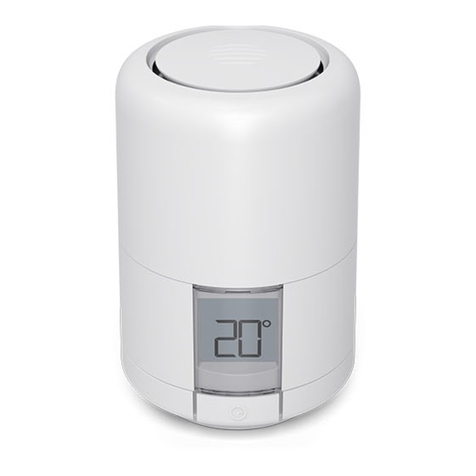
Hive
Hive Radiator Valve user guide
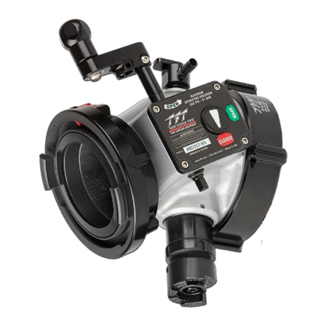
Task Force Tips
Task Force Tips Low Profile Ball Intake Valve Instructions for installation, safe operation and maintenance
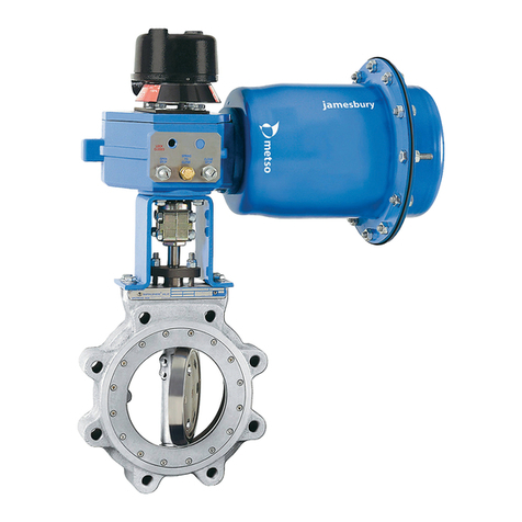
Metso
Metso Jamesbury Wafer-Sphere 8000 Series Installation maintenance and operating instructions
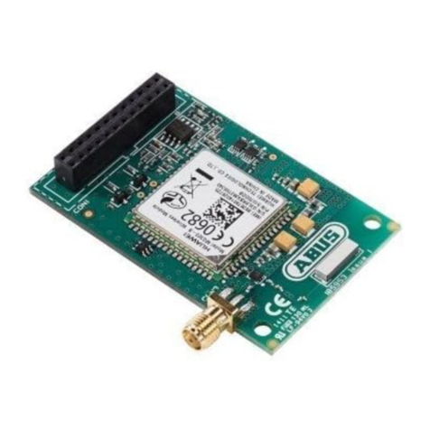
Abus
Abus FUMO50000 Installation instructions and user guide

SIGMA TEK
SIGMA TEK STO 081 instruction manual
GiBiDi
GiBiDi AS05690 Instructions for installation
Kieback&Peter
Kieback&Peter RBW322-FTL-902 operating instructions
SPX FLOW
SPX FLOW WR60 Series instruction manual
FRONIUS
FRONIUS String Control 250/ 25 DCD DF operating instructions

