AAON PREHEAT-X Quick start guide

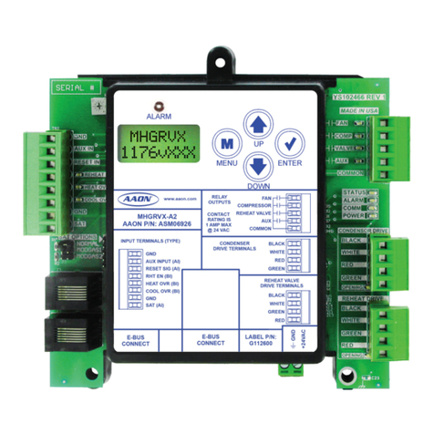
PREHEAT-X Module
Technical Guide

2PREHEAT-X Technical Guide
PREHEAT-X REVISION LOG
REVISION AND DATE CHANGE
Rev. E, April 16, 2021
Updated part numbers, alarms and alarm history, and labels. Added Figure/Table
content pages, and Fahrenheit/Celsius temperature conversion. Corrected cosmetic
errors.
AAON
2425 South Yukon Ave.
Tulsa, OK 74107-2728
www.aaon.com
Factory Technical Support Phone: 918-382-6450
AAON Controls Support: 866-918-1100
It is the intent of AAON to provide accurate and current
product information. However, in the interest of product
improvement, AAON reserves the right to change pricing,
specications, and/or design of its product without notice,
obligation, or liability.
AAON P/N: G086640, Rev. E
© April 2021 AAON Inc. All rights reserved throughout
the world.
AAON®is a registered trademark of AAON, Inc., Tulsa, OK.
AAON assumes no responsibility for errors or omissions in
this document.
This document is subject to change without notice.
www.aaon.com
PREHEAT-X PARTS REFERENCE
PART DESCRIPTION PART NUMBER
PREHEAT-X Module ASM01688
VCCX2 Controller ASM01698
VCB-X Controller ASM01862
VCM-X E-BUS Controller V07151
Air Temperature Sensor G051240 (6 in.), G051250 (12 in.)
Outside Air Sensor G042230
EBC E-BUS Cable Assembly E-BUS Power & Comm 1.5 Ft, 3 Ft,
10 Ft, 25 Ft, 50 Ft, 75 Ft, 100 Ft, 150 Ft, 250 Ft, and 1000 Foot
Spool
G029440 (1.5 Ft), G012870 (3 Ft), G029460 (10 Ft), G045270 (25 Ft),
G029510 (50 Ft), G029530 (75 Ft), G029450 (100 Ft), G029470 (150 Ft),
V36590 (250 Ft), G018870 (SPOOL)
All manuals are also available for download from
www.aaon.com/controlsmanuals.

3
PREHEAT-X Technical Guide
TABLE OF CONTENTS
OVERVIEW....................................................................................................................... 5
General Information ................................................................................................................................................ 5
WIRING ............................................................................................................................ 6
Important Wiring Considerations............................................................................................................................. 6
Inputs Wiring ........................................................................................................................................................... 7
Outputs Wiring ........................................................................................................................................................ 8
INPUTS AND OUTPUTS.................................................................................................. 9
Analog and Binary Inputs, Analog Outputs and Relays .......................................................................................... 9
SEQUENCE OF OPERATIONS....................................................................................... 10
Operation Modes .................................................................................................................................................. 10
LCD SCREENS ............................................................................................................... 12
Navigation Keys .................................................................................................................................................... 12
Main Screens Map ................................................................................................................................................ 13
Main Screens ........................................................................................................................................................ 14
Status Screens...................................................................................................................................................... 15
Setpoints Screens................................................................................................................................................. 17
Alarms Screen ...................................................................................................................................................... 18
Conguration Screens .......................................................................................................................................... 19
Communication Conguration Screens ................................................................................................................ 20
TROUBLESHOOTING .................................................................................................... 21
LED Diagnostics ................................................................................................................................................... 21
Alarms................................................................................................................................................................... 22
APPENDIX A: LAT SENSOR .......................................................................................... 23
Installation............................................................................................................................................................. 23
Troubleshooting .................................................................................................................................................... 24
APPENDIX B: BACNET®................................................................................................ 25
Connection to MS/TP Network.............................................................................................................................. 25
PREHEAT-X BACnet®Points ................................................................................................................................ 26

4PREHEAT-X Technical Guide
FIGURES AND TABLES
TABLES
Table 1: PREHEAT-X Electrical and Environmental Requirements..................................................................................6
Table 2: PREHEAT-X Inputs and Outputs.............................................................................................................................9
Table 3: Navigation Key Functions.......................................................................................................................................12
Table 4: Editing Key Functions .............................................................................................................................................12
Table 5: 0-3V Temperature Sensor - Voltage & Resistance for Type III Sensors.........................................................24
Table 6: PREHEAT-X BACnet®Points.................................................................................................................................26
FIGURES
Figure 1: PREHEAT-X Dimensions..........................................................................................................................................5
Figure 2: PREHEAT-X Inputs Wiring Diagram.......................................................................................................................7
Figure 3: PREHEAT-X Outputs Wiring Diagram....................................................................................................................8
Figure 4: LCD Display and Navigation Keys........................................................................................................................12
Figure 5: PREHEAT-X Main Screens Map ...........................................................................................................................13
Figure 6: PREHEAT-X LED Locations and Descriptions....................................................................................................21
Figure 7: Leaving Air Temperature Sensor Installation.......................................................................................................23
Figure 8: PREHEAT-X BACnet Connection to MS/TP Network........................................................................................25

5
PREHEAT-X Technical Guide
Overview
The PREHEAT-X is designed to control xed stages of Preheat
and optional modulating Preheat to maintain a desired Preheat
Leaving Air Temperature Setpoint. See Figure 1, this page for
dimensions. See Figure 2 and 3, pages 7 and 8 for wiring details.
Features
The PREHEAT-X has the following features:
• Can be operated as a stand-alone module or comm-
unicating with the VCCX2 or other AAON unit
controllers.
• Monitors the Preheater Leaving Air Temperature and
Leaving Air Reset Signal and controls to maintain the
setpoint
• Contains a 2 x 8 LCD character display and four buttons
that allow for status display and setpoint changes
Figure 1: PREHEAT-X Dimensions
5.73
5.24
2.62
5.63
5.04
0.21
2.04
0.57
4.09 Note: Depth is 1.50 inches.
Note: All dimensions are in inches.
OVERVIEW
General Information
NOTE: The PREHEAT-X contains no user-serviceable
parts. Contact qualied technical personnel if your
PREHEAT-X is not operating correctly.

6PREHEAT-X Technical Guide
Wiring
The modules must be connected to an 18-30 VAC power source
of the proper size for the calculated VA load requirements. All
transformer sizing should be based on the VA ratings listed in
Table 1, this page.
NOTE: If the temperature at the PREHEAT-X is below
-22ºF (-30ºC), the display refresh rate could be
less responsive.
WARNING: When using a single transformer to power
more than one controller or expansion
module, the correct polarity must always
be maintained between the boards. Failure
to observe correct polarity will result in
damage to the AAON unit controller,
PREHEAT-X, and any associated module.
Please carefully read and apply the following information
when wiring the AAON unit controller, PREHEAT-X and any
associated module.
1. All wiring is to be in accordance with local and
national electrical codes and specications.
2. All 24 VAC wiring must be connected so that all
ground wires remain common. Failure to follow this
procedure can result in damage to the controller and
connected devices.
3. Minimum wire size for 24 VAC wiring should be
18-gauge.
4. Minimum wire size for all sensors should be 24-gauge.
Some sensors require two-conductor wire and some
require three-or four-conductor wire.
5. Minimum wire size for 24 VAC thermostat wiring
should be 22-gauge.
6. Be sure that all wiring connections are properly
inserted and tightened into the terminal blocks. Do
not allow wire strands to stick out and touch adjoining
terminals which could potentially cause a short circuit.
7. When communication wiring is to be used to
interconnect AAON unit controllers together or to
connect to other communication devices, all wiring
must be plenum-rated, minimum 18-gauge, two-
conductor, twisted-pair with shield. AAON can supply
communication wire that meets this specication and
is color coded for the network or local loop. Please
consult your AAON distributor for information. If
desired, Belden #82760 or equivalent wire may also
be used.
8. Before applying power to the AAON unit controller,
PREHEAT-X, and any associated modules, be sure
to recheck all wiring connections and terminations
thoroughly.
Powering Up
When the controller and modules are rst powered up, the
POWER LED should light up and stay on continuously. If it does
not light up, check to be sure that you have 24 VAC connected
to the controller, that the wiring connections are tight, and that
they are wired for the correct polarity. The 24 VAC power must
be connected so that all ground wires remain common. If after
making all these checks, the POWER LED does not light up,
please contact AAON Controls Support for assistance.
Control
Device
Voltage
VA Load
Operating
Temperature
Humidity
(Non-
Condensing)
PREHEAT-X
18-30 VAC 18 -22°F to 158°F*
-30ºC to 70ºC* 0-95% RH
Inputs
Resistive Inputs require 10KΩ
Type III Thermistor
24 VAC Inputs provide 4.7KΩ
Load
Outputs Relay Outputs: 1 amp
maximum per output.
Table 1: PREHEAT-X Electrical and Environmental
Requirements
WIRING
Important Wiring Considerations
7
PREHEAT-X Technical Guide
Inputs
The PREHEAT-X works as a stand-alone module or comm-
unicating with the VCCX2 or other AAON unit controllers. For
connection to the PREHEAT-X use an E-BUS Cable connecting
to the appropriate E-BUS ports. The Reset Input and Heat Enable
are only used in Stand-Alone Mode. See Figure 2,this page for
the Inputs Wiring Diagram.
Leaving Air 1
Temperature Sensor
Mount inside
PREHEAT-X box wall
Leaving Air 2
Temperature Sensor
Mount inside
PREHEAT-X box wall
Entering Air
Temperature Sensor
Make splice
connections inside
sensor enclosure
as shown. Seal all
conduit fittings with
silicone sealant.
Mount sensor outdoors
in shaded protected
area and in upright
position as shown.
0-10 VDC
Reset In GND
Heat Enable
Signal (24 VAC)
W1
Note: Reset In and Heat Enable inputs
are used in Stand-Alone Mode only.
Emergency
Shutdown
AI1
AI2
AI3
RST
GND
GND
BI1
BI2
COM
Size transformer for correct total load.
PREHEAT-X Controller = 11VA
N.C.
SAFETIES
(by others)
GND 18-30
VAC
Line
Voltage
Figure 2: PREHEAT-X Inputs Wiring Diagram
WIRING
Inputs Wiring

8PREHEAT-X Technical Guide
Outputs
The PREHEAT-X works as a stand-alone module or
communicating with the VCCX2 or other AAON unit controllers.
For connection to the PREHEAT-X, use an E-BUS Cable
connecting to the appropriate E-BUS ports. See Figure 3,this
page for the Outputs Wiring.
1 amp maximum load.
Note: All relay outputs are normally open
and rated for 24 VAC power only.
PREHEAT-X = 11VA
Size transformer for correct total load.
EBC E-BUS cable connects to
VCCX2 or other AAON unit
controller’s expansion port.
HSSC E-BUS cable
connects to the VCM-X
Controller’s expansion
port
ALARM
HEAT1RELAY
HEAT2RELAY
HEAT3RELAY
HEAT4RELAY
HEAT5RELAY
HEAT6RELAY
Relay
Contact
Modulating SCR
(0-10 VDC)
PWM SSR
GND
VAC
18-30
Line
Voltage
Figure 3: PREHEAT-X Outputs Wiring Diagram
WIRING
Outputs Wiring

9
PREHEAT-X Technical Guide
INPUTS AND OUTPUTS
Analog and Binary Inputs, Analog Outputs and Relays
I/O Map
See Table 2, this page to reference the inputs and outputs that
are available on the PREHEAT-X.
Analog Inputs
Leaving Air Temperature 1 (LAT1)
When enabled, the PREHEAT-X will control to a Leaving Air
Temperature (LAT) setpoint. The PREHEAT-X can be congured
to use only LAT1 for this purpose. Typically, the average of LAT1
and LAT2 is used.
Leaving Air Temperature 2 (LAT2)
When enabled, the PREHEAT-X will control to a Leaving Air
Temperature Setpoint. It can be congured to use only LAT2 for
this purpose. Typically, the average of LAT1 and LAT2 is used.
Entering Air Temperature
When the Entering Air Temperature falls below the Entering Air
Temperature Setpoint, preheat will be enabled.
Reset Input (0-10 VDC)
When the PREHEAT-X is used as a stand-alone module, the
Leaving Air Temperature Setpoint can be reset by supplying
a 0-10 VDC signal to the RST IN low voltage terminal block.
This reset signal is optional and need only be used if you require
resetting of the Discharge Air Temperature.
Binary Inputs
Heat Enable Contact (HEAT EN)
This input is only required when the PREHEAT-X is used as
stand-alone module; it is not required when communicating with
an AAON unit controller. The Heat Enable input is activated by
a 24 VAC signal supplied from a building automation system to
enable the PREHEAT-X. The module will not operate without 24
VAC being applied to this input terminal when used as a stand-
alone module. When the Heat Enable signal is lost or turned o,
all stages deactivate immediately.
Emergency Shutdown Input
This wet contact (24 VAC) input is used to initiate shutdown of
the HVAC unit when a N.C. Smoke Detector (by others), Firestat
(by others), or other shutdown condition (by others) occurs and
the contact is opened. The PREHEAT-X remains active and can
initiate alarm relays.
Analog Outputs
0-10 VDC Modulating SCR
Depending on the type of Heat used, this output will supply a
0-10 VDC output signal for control of the modulating SCR Heat.
Pulse Width Modulating SSR
Depending on the type of Heat used, this output will supply a 12 V
PWM Output Signal for control of the modulating SSR Heat.
Relay Outputs
Relay #1 - Alarm
This relay sends a signal when an alarm is enabled.
Relays #2 - 7
These relays are Fixed Stage Heat Outputs.
Table 2: PREHEAT-X Inputs and Outputs
Analog Inputs
1Leaving Air Temperature 1 (LAT1)
2Leaving Air Temperature 2 (LAT2)
3Entering Air Temperature Sensor
4Reset In (0-10 VDC)
Binary Inputs
1Heat Enable
2Emergency Shutdown
3Future Use
Analog Outputs
10-10 VDC Mod SCR
2PWM SSR
Relays
1Alarm
2Heat 1
3Heat 2
4Heat 3
5Heat 4
6Heat 5
7Heat 6
NOTE: For AIN1 through AIN3, all temperature sensors
must be Thermistor Type III Temperature Sensors,
which provide 77.0ºF @ 10K ohms resistance.

10 PREHEAT-X Technical Guide
Operation Modes
The PREHEAT-X can be used as a stand-alone module or
communicating with an AAON unit controller using a modular
cable.
Stand-Alone Mode
When used in Stand-Alone Mode, the PREHEAT-X will
modulate SCR or SSR Heat and stage any additional xed stages
to maintain the Leaving Air Temperature Setpoint congured on
the PREHEAT-X LCD display. The PREHEAT-X is activated by
a 24 VAC signal to the HEAT EN input.
Communications Mode
When the PREHEAT-X is connected and communicating with
an AAON unit controller via a modular cable, the necessary
information will be passed between the PREHEAT-X and the
AAON unit controller to properly operate in the Heating Mode.
If the communication is interrupted between the PREHEAT-X
and the AAON unit controller, both boards will show an alarm
and the PREHEAT-X outputs will turn o. When communication
is restored, the alarms will go away.
In this conguration, the Leaving Air Temperature Setpoints
and the Preheat Enable Sepoints are set using the main AAON
unit controller.
SEQUENCE OF OPERATIONS
Operation Modes

11
PREHEAT-X Technical Guide
Preheat Enable
Stand-Alone Mode
Enabled when the Binary Input is closed and the Entering Air
Temperature is below setpoint.
E-BUS Communications Mode
Enabled by an E-BUS command when the Entering Air
Temperature falls below the Preheat Setpoint.
BACnet Communications Mode
Enabled by BACnet® command or Binary Input, whichever
occurs rst.
Leaving Air Sensor
The PREHEAT-X can be congured to use one of three sensor
congurations for control.
• Leaving Air Sensor 1 only (LAT1)
• Leaving Air Sensor 2 only (LAT2)
• Average Leaving Air Temperature which averages
LAT1 and LAT2
Leaving Air Setpoint
Stand-Alone
• Leaving Air Temperature Setpoint can be reset between
the LAT Setpoint and LAT Setpoint Reset Limit.
• The Reset Source is based on a 0-10 VDC input and
range can be adjusted using the LAT Setpoint Reset
Source Low and LAT Setpoint Reset Source High
Setpoints.
E-BUS and BACnet Communications Mode
• A Leaving Air Temperature Setpoint will be sent to
the controller.
• This value is stored in volatile memory and will be
lost at reset.
• There are separate Leaving Air Temperature setpoints,
depending on if the unit is in Heating, Vent, or Cool
Mode.
Modulating Heat
• If congured, the Modulating Heat Output will be used
as the rst stage of heat.
• Analog Voltage Output can be adjusted between 0-10
VDC as needed to maintain the Leaving Air Setpoint.
• Controlled by an Internal PID Loop.
Heat Staging Up
The following conditions must be met before the rst (next) stage
of heat can be energized:
• Preheat Enable Signal/Command must be active.
• The LAT must be below the LAT Setpoint by any
amount.
• If Mod Heat is congured, it must be at 100% for the
Stage Up Delay.
• The Minimum O Time must be met.
• The Stage Up Delay must be met (for second stage
and above).
Heat Staging Down
The following conditions must be met before a stage of heat can
be de-energized:
• Preheat Enable Signal/Command is deactivated -OR-
the LAT must be above the LAT Setpoint by the LAT
Deadband.
• If Modulating Heat is congured, it must be at 0% for
the Stage Down Delay.
• The Minimum Run Time must be met.
• The Stage Down Time must be met.
Emergency Shutdown
The Emergency Shutdown Input must always be used and wired
as a 24 VAC normally closed contact. If an Emergency Shutdown
occurs, and that contact opens:
• All outputs will be immediately de-energized.
• An alarm will be generated.
High Leaving Air Temperature Alarm
If the Leaving Air Temperature is above the LAT High
Temperature Alarm Limit for more than the Alarm Delay, all
heating outputs will be de-energized immediately.
• An alarm will be generated.
• A manual reset will be required.
Low Leaving Air Temperature Alarm
If the Leaving Air Temperature is below the LAT Low
Temperature Alarm Limit for more than two minutes, the heat
will remain on but an alarm will be generated.
SEQUENCE OF OPERATIONS
Operation Modes

12 PREHEAT-X Technical Guide
LCD Display Screen & Navigation Keys
The LCD display screens and buttons allow you to view status
and alarms, and enable force modes. See Figure 4, this page and
refer to Table 3 and 4, this page for descriptions.
Figure 4: LCD Display and Navigation Keys
Table 3: Navigation Key Functions
ALARM
UP
DOWN
ENTERMENU
LCD SCREENS
Navigation Keys
Navigation
Key Key Function
MENU Use the MENU key to move through screens
within Main Menu categories and return to the
Main Menu while at other screens.
UP Use this key to adjust setpoints and change
congurations.
DOWN Use this key to adjust setpoints and change
congurations.
ENTER Use the ENTER key to navigate through the Main
Menu Screen categories.
Editing
Key Key Function
UP
or
DOWN
Use the UP or DOWN key to enter editing mode
on a user-adjustable screen. Edit Mode is indicat-
ed by the underscore appearing on the screen.
NOTE: Entering Edit Mode will also adjust the
value up one (UP key) or down one (DOWN key),
so you may have to readjust the value.
ENTER
Use the ENTER key to move through the digits
in the screen when editing a numeric value. An
extended press of the ENTER key saves your
edits no matter the location of the editing cursor
within the digits.
Press the ENTER key to save a non-numeric
value such as Hi Speed Network.
MENU
The MENU key cancels editing when in Edit Mode.
The screen you were editing will return to its
original value and the underscore will disappear.
A second press of the MENU key will return you to
the Main Menu.
Table 4: Editing Key Functions

13
PREHEAT-X Technical Guide
CONFIG
HEAT STG
X
MOD HEAT
YES
LAT CFG
AVERAGE
AOUT VLO
X.X
AOUT VHI
XX.X
STG UP
XX
STG DWN
XX
MIN RUN
XX
MIN OFF
XX
SCALING
DEG.F
SET
POINTS
LA1 CAL
XX.X
LA2 CAL
XX.X
EA CAL
XX.X
PREHEAT
CONTROL
COMM
CONFIG
COM MODE
S-ALONE
MAC ADDR
0
BAC ID
15000
BAC BAUD
38.400
EBUS CFG
VCB/VCCX
STATUS
SOFTWARE
VER X.XX
PREHEAT
ENABLED
CONT TMP
XX.X
LA SPT
XX.X
STGS ON
2
MOD HEAT
XX%
LA1 TEMP
XX.X
LA2 TEMP
XX.X
AVG TEMP
XX.X
ENT AIR
XX.X
CommPKTs
XX
ALARMS
E-SHUTDN
ALARM
LA1 SENS
BAD
LA2 SENS
BAD
LOW LAT
ALARM
HI LAT
ALARM
EA SENS
ALARM
COM STAT
ALARM
ACTIVE
ALARMS
Figure 5: PREHEAT-X Main Screens Map
LCD SCREENS
Main Screens Map

14 PREHEAT-X Technical Guide
PREHEAT
CONTROL
Press to scroll through PREHEAT-X Screens.
Press to go to STATUS Screens.
STATUS
Press to scroll through STATUS Screens.
Press to go to SETPOINTS Screens.
SET
POINTS
Press to scroll through SETPOINTS Screens.
Press to go to ALARMS Screens.
ALARMS
Press to scroll through ALARMS Screens.
Press to go to CONFIG Screens.
CONFIG
Press to scroll through CONFIG Screens.
Press to go to COMM CONFIG Screens.
Main Screens
Refer to the following map when navigating through the LCD
Main Screens. The rst screen is an initialization screen. To
scroll through the rest of the screens, press the <MENU> button.
COMM
CONFIG
Press to scroll through COMM CONFIG Screens.
LCD SCREENS
Main Screens

15
PREHEAT-X Technical Guide
Status Screens
Refer to the following map when navigating through the Status
Screens. From the STATUS Screen, press <ENTER> to scroll
through the screens.
STATUS
Status Screens shown below automatically if LCD display is left on
the screen for 20 seconds.
SOFTWARE
VER X.XX
CURRENT SOFTWARE VERSION
Displays the current software version installed in the module.
PREHEAT
ENABLED
PREHEAT
Gives the Enabled status for the Preheat Mode. The PREHEAT-X
can be enabled from one of the following: (1) Binary Input in Stand-
Alone Mode, (2) E-BUS command from VCCX2 or other AAON unit
controllers, or (3) BACnet point.
CONT TMP
XX.X
CONTROL TEMPERATURE
Displays the current controlling temperature. This could be one of
the following based on conguration: (1) Leaving Air Sensor 1,
(2) Leaving Air Sensor 2, or (3) the average of both.
.
LA SPT
XX.X
LEAVING AIR TEMPERATURE SETPOINT
Displays the current Leaving Air Setpoint the module is trying to
maintain. This value can come from the following based on
conguration: (1) Internal Setpoints +/- Setpoint Reset Input,
(2) E-BUS Input from VCCX2 or other AAON unit controllers or
(3) BACnet point.
.
STGS ON
2
CURRENT NUMBER OF ACTIVE STAGES
Displays the number of heat stages currently energized.
This includes the First Modulating Stage of Heat.
.
MOD HEAT
XX%
MODULATING HEATING OUTPUT
Displays the current Modulation Output Percentage of both the
Analog and PWM outputs (they control together).
LA1 TEMP
XX.X
LEAVING AIR TEMPERATURE 1
Displays the Leaving Air Temperature 1 Sensor’s current reading.
LA2 TEMP
XX.X
LEAVING AIR TEMPERATURE 2
Displays the Leaving Air Temperature 2 Sensor’s current reading.
AVG TEMP
XX.X
AVERAGE TEMPERATURE
Displays the current average temperature of both
Leaving Air Temperature Sensors.
LCD SCREENS
Status Screens

16 PREHEAT-X Technical Guide
ENT AIR
XX.X
ENTERING AIR TEMPERATURE
Displays the current Entering Air Temperature Sensor reading.
CommPKTs
XX
COMMUNICATION PACKETS
Communication Packets are used to show the EBUS packets re-
ceived from main controller.
LCD SCREENS
Status Screens

17
PREHEAT-X Technical Guide
Setpoint Screens
Refer to the following map when navigating through the Setpoint
Screens. From the SETPOINTS Screen, press <ENTER> to
scroll through the screens and change setpoints. Use the <UP>
and <DOWN> arrow keys to change your selections. Then press
<ENTER> to save the new setpoint.
NOTE: When the PREHEAT-X is operating in
Communications Mode, these setpoint screens
will not appear on the LCD display because they
are controlled by the Main Controller.
SET
POINTS
LA1 CAL
XX.X
LEAVING AIR SENSOR 1 CALIBRATION OFFSET
If the sensor is reading incorrectly, you can use this screen to enter
an oset temperature to adjust the sensor’s temperature. Enter a
positive value to raise the sensor’s temperature or a negative value
to lower the sensor’s temperature.
Minimum Default Maximum
-100ºF 0.0ºF 100ºF
-55.5ºC 21ºC 55.5ºC
LA2 CAL
XX.X
LEAVING AIR SENSOR 2 CALIBRATION OFFSET
If the sensor is reading incorrectly, you can use this screen to enter
an oset temperature to adjust the sensor’s temperature. Enter a
positive value to raise the sensor’s temperature or a negative value
to lower the sensor’s temperature.
Minimum Default Maximum
-100ºF 0.0ºF 100ºF
-55.5ºC 21ºC 55.5ºC
EA CAL
XX.X
ENTERING AIR SENSOR CALIBRATION OFFSET
If the sensor is reading incorrectly, you can use this screen to enter
an oset temperature to adjust the sensor’s temperature. Enter a
positive value to raise the sensor’s temperature or a negative value
to lower the sensor’s temperature.
Minimum Default Maximum
-100ºF 0.0ºF 100ºF
-55.5ºC 21ºC 55.5ºC
LCD SCREENS
Setpoints Screens

18 PREHEAT-X Technical Guide
Alarms Screen
Refer to the following map when viewing the ALARMS Screens.
These screens will display automatically when alarms are present.
For alarm troubleshooting, see pages 22-23.
The alarms are as follows:
NO ALARMS: This will be shown if there are no current alarms.
E-SHUTDN: If 24VAC is removed from the Emergency Shutdown
Input, this alarm will activate and the controller will turn o all
outputs. The alarm will be disabled when voltage has returned.
LA1 SENS: The rst Leaving Air Temperature sensor has been
disconnected, shorted, open, or missing for more than 60 seconds.
This alarm will be disabled when the sensor is working again.
LA2 SENS: The second Leaving Air Temperature sensor has been
disconnected, shorted, open, or missing for more than 60 seconds.
This alarm will be disabled when the sensor is working again.
LOW LAT: This indicates a Leaving Air Temperature Cuto
alarm condition which is activated if the Controlling Leaving Air
Temperature has dropped below 35ºF for more than 2 minutes.
The alarm will be disabled if after a xed delay period the
Leaving Air Temperature has risen above 35ºF.
HI LAT: This indicates a Leaving Air Temperature Cuto alarm
condition which is activated if the Controlling Leaving Air
Temperature has risen above 120ºF. All outputs will stage o.
EA SENS: The Entering Air Temperature sensor has been
disconnected, open, shorted, or missing for more than 60 seconds.
This alarm will be disabled when the sensor is working again.
COM STAT: Communications have been lost with the main
controller for more than 30 seconds. This alarm will disable
when communications resume.
ALARMS
ALARMS
LCD SCREENS
Alarms Screen

19
PREHEAT-X Technical Guide
Conguration Screens
Refer to the following map when navigating through the
Configuration Screens. From the CONFIG Screen, press
<ENTER> to scroll through the screens and change setpoints. Use
the <UP> and <DOWN> arrow keys to change your selections.
Press <ENTER> to save any changes.
CONFIG
HEAT STG
X
# OF HEAT STAGES
Select the total number of Heat Stages including the Modulating
Stage. Range is 0-6. Default is 0.
MOD HEAT
YES
MODULATING HEAT
If either the Analog or PWM Modulating Heat output is being used,
this must be set to YES. Default is NO.
LAT CFG
AVERAGE
LEAVING AIR TEMPERATURE SENSOR CONFIGURATION
LAT1: Use Leaving Air Temperature Sensor 1 as the Controlling Temp.
LAT2: Use Leaving Air Temperature Sensor 2 as the Controlling Temp.
AVERAGE: Use the Average of LAT1 & LAT2 as the Controlling Temp.
Default is AVERAGE.
AOUT VLO
X.X
MINIMUM SCR VOLTAGE
This is the Low Voltage setting for the Analog Output. It sets the
voltage level needed for 0%. Range is 0 -10. Default is 0
AOUT VHI
XX.X
MAXIMUM SCR VOLTAGE
This is the High Voltage setting for the Analog Output. It sets the
voltage level needed for 100%. Range is 0 -10. Default is 10.
STG UP
XX
STAGE UP DELAY
If congured for SCR modulation, this is the amount of time (in
seconds) the controller must wait to activate an additional stage of
heat if the Min O Time is met. Range is 0 - 1200. Default is 180.
STG DWN
XX
STAGE DOWN DELAY
If congured for SCR modulation, This is the amount of time (in
seconds) the controller must wait to deactivate a stage of heat if the
Min Run time is met. Range is 0 - 1200. Default is 180.
MIN RUN
XX
MINIMUM RUN TIME
This is the amount of time (in seconds) a stage of heat must remain
on before it can be deactivated. Range is 0 - 1200. Default is 120.
MIN OFF
XX
MINIMUM OFF TIME
This is the amount of time (in seconds) a stage of heat must remain o
before it can be activated. Range is 0 - 1200. Default is 60.
SCALING
DEG.F
TEMPERATURE SCALE
Fahrenheit (default) or Celsius.
This setting is used only in Stand-Alone Mode.
LCD SCREENS
Conguration Screens

20 PREHEAT-X Technical Guide
COMM
CONFIG
COM MODE
S-ALONE
COMMUNICATIONS MODE
This setting congures the Communications Mode. The choices are
(1) BACNET, (2) EBUS, or (3) S-ALONE (default).
EBUS CFG
VCB/VCCX
E-BUS CONFIGURATION
Select the type of controller that the PREHEAT-X is connected to.
NOTE: You must cycle power after changing to apply this setting.
MAC ADDR
0
BACnet®- CURRENT MAC ADDRESS
Valid range is 0 to 128. Default is 0.
.
BAC ID
15000
BACnet®- CURRENT ID START
Range is 0 to 30000. Default is 15000.
Communication Conguration Screens
Refer to the following map when navigating through the
Communication Configuration Screens. From the COMM
CONFIG Screen, press <ENTER> to scroll through the screens
and change setpoints. Use the <UP> and <DOWN> arrow keys
to change your selections. Press <ENTER> to save any changes.
BAC BAUD
38,400
BACnet® - CURRENT BAUD RATE
9600, 19200, 38400, 57600, 76800. Default is 38400.
LCD SCREENS
Communication Conguration Screens
Table of contents
Other AAON Control Unit manuals

AAON
AAON RSMD Quick start guide

AAON
AAON MODGAS-XWR2 Quick start guide

AAON
AAON SS1068 User manual

AAON
AAON MODGAS-XWR2-B Quick start guide

AAON
AAON RSMVQ2R Quick start guide

AAON
AAON HP2C2 Quick start guide

AAON
AAON RSMV ASM01686 Quick start guide

AAON
AAON RSM-DEV1 Quick start guide

AAON
AAON RSMD-CM Quick start guide

AAON
AAON RSMVQ Quick start guide
Popular Control Unit manuals by other brands

Gemalto
Gemalto SafeNet ProtectServer Installation and configuration guide

Comfort365
Comfort365 WDDCK installation manual

Torex
Torex RV Installation, operation and maintenance

Acuity Controls
Acuity Controls xCella XCR RM 1RL DNI Setup & Pairing Guide

VIPA
VIPA TM-E 900-1E640 manual

Siko
Siko AEA111/1 User information