manuals.online logo
Brands
  1. Home
  2. •
  3. Brands
  4. •
  5. PRESIDENT
  6. •
  7. Radio
  8. •
  9. PRESIDENT HARRY III User manual

PRESIDENT HARRY III User manual

Other manuals for HARRY III

1

Other PRESIDENT Radio manuals

PRESIDENT JOHNNY III ASC 12/24 User manual

PRESIDENT

PRESIDENT JOHNNY III ASC 12/24 User manual

PRESIDENT RANDY FCC User manual

PRESIDENT

PRESIDENT RANDY FCC User manual

PRESIDENT JOHNSON II User manual

PRESIDENT

PRESIDENT JOHNSON II User manual

PRESIDENT ANDY II FCC User manual

PRESIDENT

PRESIDENT ANDY II FCC User manual

PRESIDENT Harry 3 User manual

PRESIDENT

PRESIDENT Harry 3 User manual

PRESIDENT MC-8050 DSC User manual

PRESIDENT

PRESIDENT MC-8050 DSC User manual

PRESIDENT TAYLOR III User manual

PRESIDENT

PRESIDENT TAYLOR III User manual

PRESIDENT LINCOLN User manual

PRESIDENT

PRESIDENT LINCOLN User manual

PRESIDENT BILLY User manual

PRESIDENT

PRESIDENT BILLY User manual

PRESIDENT GRANT CLASSIC User manual

PRESIDENT

PRESIDENT GRANT CLASSIC User manual

PRESIDENT MC KINLEY II FCC User manual

PRESIDENT

PRESIDENT MC KINLEY II FCC User manual

PRESIDENT JFK II A+ User manual

PRESIDENT

PRESIDENT JFK II A+ User manual

PRESIDENT HARRY III CLASSIC User manual

PRESIDENT

PRESIDENT HARRY III CLASSIC User manual

PRESIDENT THOMAS FCC AM/FM User manual

PRESIDENT

PRESIDENT THOMAS FCC AM/FM User manual

PRESIDENT Bill ASC User manual

PRESIDENT

PRESIDENT Bill ASC User manual

PRESIDENT TRUMAN User manual

PRESIDENT

PRESIDENT TRUMAN User manual

PRESIDENT Grant II User manual

PRESIDENT

PRESIDENT Grant II User manual

PRESIDENT WALKER ASC Classic User manual

PRESIDENT

PRESIDENT WALKER ASC Classic User manual

PRESIDENT Jackson User manual

PRESIDENT

PRESIDENT Jackson User manual

PRESIDENT JOHNSON II User manual

PRESIDENT

PRESIDENT JOHNSON II User manual

PRESIDENT JOHNSON II User manual

PRESIDENT

PRESIDENT JOHNSON II User manual

PRESIDENT Randy II M User manual

PRESIDENT

PRESIDENT Randy II M User manual

PRESIDENT MC Kinley TXPR600 User manual

PRESIDENT

PRESIDENT MC Kinley TXPR600 User manual

PRESIDENT HENRY classic ASC 12/24 User manual

PRESIDENT

PRESIDENT HENRY classic ASC 12/24 User manual

Popular Radio manuals by other brands

EisSound KBSound iSelect user manual

EisSound

EisSound KBSound iSelect user manual

Midland 1001LWX owner's manual

Midland

Midland 1001LWX owner's manual

Konig HAV-SR41 manual

Konig

Konig HAV-SR41 manual

Roberts exprssion manual 

Roberts

Roberts exprssion manual 

VDigi DD3.0 Operation manual

VDigi

VDigi DD3.0 Operation manual

Radio Shack 21-1863 owner's manual

Radio Shack

Radio Shack 21-1863 owner's manual

Roberts Stream 207 instruction manual

Roberts

Roberts Stream 207 instruction manual

Sony Walkman SRF-M97 Service manual

Sony

Sony Walkman SRF-M97 Service manual

Stanley FatMax FMC770 manual

Stanley

Stanley FatMax FMC770 manual

auna DAB-Radio 10026947 manual

auna

auna DAB-Radio 10026947 manual

SOUNDMASTER UR190 instruction manual

SOUNDMASTER

SOUNDMASTER UR190 instruction manual

HYT TC-320 user manual

HYT

HYT TC-320 user manual

B-Tech GMRS-V2 manual

B-Tech

B-Tech GMRS-V2 manual

Weierwei VEV-V8 user manual

Weierwei

Weierwei VEV-V8 user manual

SOUNDMASTER DAB750 instruction manual

SOUNDMASTER

SOUNDMASTER DAB750 instruction manual

Telefunken TF-1505 instruction manual

Telefunken

Telefunken TF-1505 instruction manual

Makita LXRM03 instruction manual

Makita

Makita LXRM03 instruction manual

FRIENDCOM FC-302V user manual

FRIENDCOM

FRIENDCOM FC-302V user manual

manuals.online logo
manuals.online logoBrands
  • About & Mission
  • Contact us
  • Privacy Policy
  • Terms and Conditions

Copyright 2025 Manuals.Online. All Rights Reserved.

Manuel d’utilisation / Manual del usuario
Owner’s manual / Instrukcja obsługi
Votre PRESIDENT HARRY III ASC en un coup d’œil Un vistazo a vuestro PRESIDENT HARRY III ASC
Twój PRESIDENT HARRY III ASC
Your PRESIDENT HARRY III ASC at a glance
SOMMAIRE
INSTALLATION 5
UTILISATION 7
CARACTÉRISTIQUES TECHNIQUES 11
GUIDE DE DÉPANNAGE 11
COMMENT ÉMETTRE/RECEVOIR UN MESSAGE 11
GLOSSAIRE 12
DÉCLARATION DE CONFORMITÉ 15
GARANTIE 16
TABLEAUX DES FRÉQUENCES 53 ~ 55
NORMES EUROPÉENNES 56
SUMARIO
INSTALACIÓN 19
UTILIZACIÓN 21
CARACTERÍSTICAS TÉCNICAS 25
GUÍA DE PROBLEMAS 25
COMO EMITIR O RECIBIR UN MENSAJE 25
LÉXICO 26
GARANTÍA 28
DECLARACIÓN CE DE CONFORMIDAD 30
TABLAS DE FRECUENCIAS 53 ~ 55
NORMAS EUROPEAS 56
SUMMARY
INSTALLATION 32
HOW TO USE YOUR CB 34
TECHNICAL CHARACTERISTICS 38
TROUBLE SHOOTING 38
HOW TO TRANSMIT OR RECEIVE A MESSAGE 38
GLOSSARY 39
CERTIFICATE OF CONFORMITY 41
FREQUENCY TABLES 53 ~ 55
EUROPEAN NORMS 56
SPIS TREŚCI
INSTALOWANIE 43
UŻYTKOWANIE RADIOTELEFONU 45
DANE TECHNICZNE 49
INSTRUKCJA POSTĘPOWANIA W PRZYPADKU
PROBLEMÓW Z RADIEM 49
JAK NADAWAĆI ODBIERAĆINFORMACJE 49
SŁOWNIK 50
ZOBOWIĄZANIA GWARANTA 50
DEKLARACJA ZGODNOŚCI 52
TABELA CZĘSTOTLIWOŚCI 53 ~ 55
NORMY EUROPEJSKIE 56
Français
Polski
Español
English
3
WARNING !
Before using, be careful never to transmit
without first having connected the antenna
(connection «B» situated on the back panel
of the equipment) or without having set the
SWR (Standing Wave Ratio) ! Failure to do so
may result in destruction of the power ampli-
fier, which is not covered by the guarantee.
The garantee of this transceiver is valid only in the country pf purchase.
MULTI-NORMS TRANSCEIVER!
See function “F” on page 35 and the Con-
figuration table on page 56.
English
31
MOUNTING
DIAGRAM
WelcometotheworldofthenewgenerationofCBradios.ThenewPRESIDENT
range gives you access to top performance CB equipment. With the use
ofup-to-datetechnology,whichguaranteesunprecedentedquality,your
PRESIDENT HARRY III ASC is a new step in personal communication and is
the surest choice for the most demanding of professional CB radio users. To
ensure that you make the most of all its capacities, we advise you to read
carefullythismanualbeforeinstallingandusingyourPRESIDENTHARRYIIIASC.
A) INSTALLATION
1) WHERE AND HOW TO MOUNT YOUR MOBILE CB RADIO
a) You should choose the most appropriate setting from a simple and practical point
of view.
b) Your CB radio should not interfere with the driver or the passengers.
c) Remember to provide for the passing and protection of different wires (e.g. power,
antenna,accessory cabling) so thatthey do notinany way interferewith the driving
of the vehicle. d) Toinstallyourequipment, use the cradle(1)andthe self-tapping screws (2)provided
(drilling diameter 3.2 mm). Take care not to damage the vehicle’s electrical system
while drilling the dash board.
e) Do not forget to insert the rubber joints (3) between the CB and its support as these
have a shock-absorbing effect which permits gentle orientation and tightening of
the set.
f) Choosewheretoplacethemicrophonesupportandrememberthatthemicrophone
cord must stretch to the driver without interfering with the controls of the vehicle.
- N.B. : As the transceiver has a frontal microphone socket, it can be set into the dash
board. In this case, you will need to add an external loud speaker to improve the
sound quality of communications (connector EXT.SP situated on the back panel: D).
Ask your dealer for advice on mounting your CB radio.
English
32
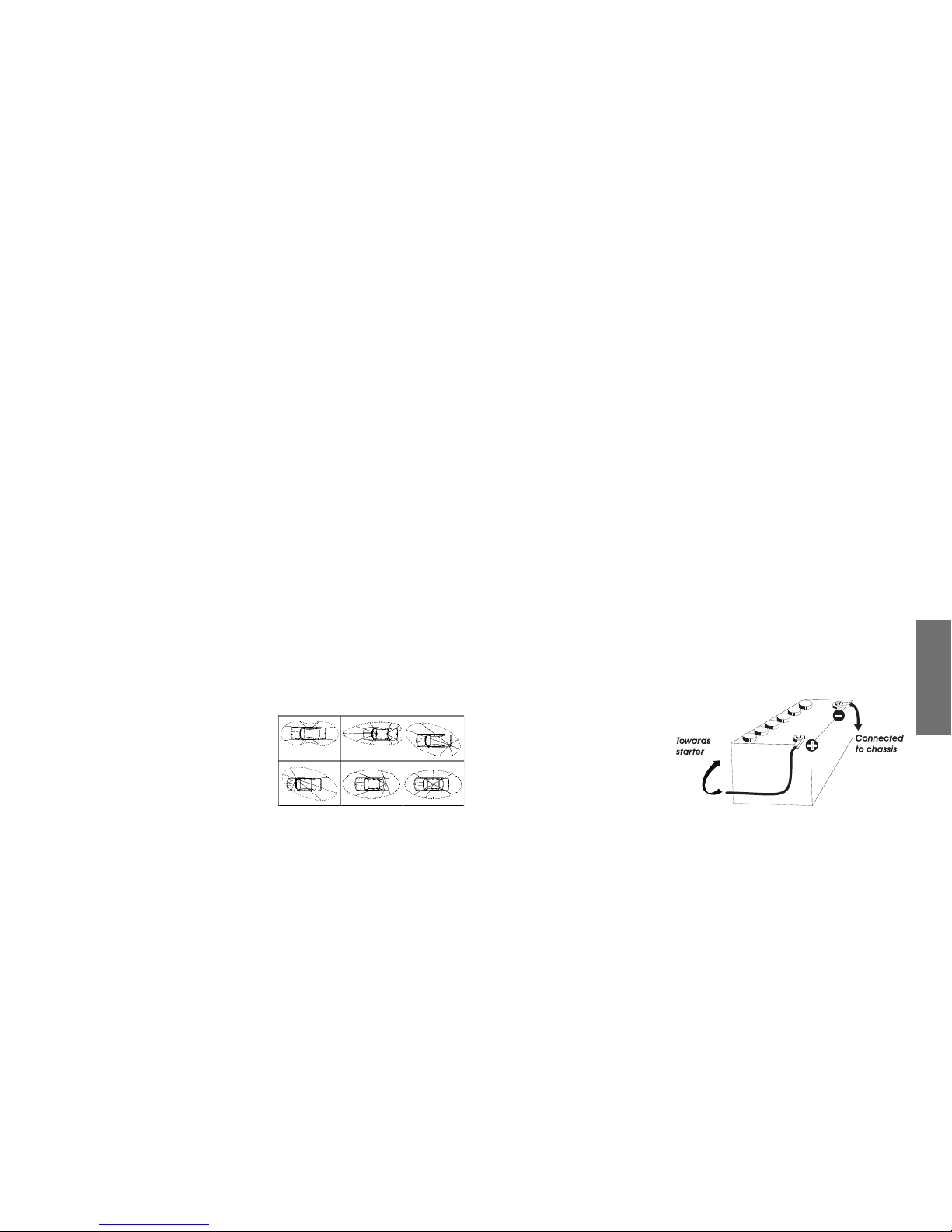
OUTPUT RADIUS PATTERN
2) ANTENNA INSTALLATION
a)Choosing your antenna:
- For CB radios, the longer the antenna, the better its results. Your dealer will be able
to help you with your choice of antenna.
b)Mobile antenna:
- Must be fixed to the vehicle where there is a maximum of metallic surface (ground
plane), away from windscreen mountings.
- If you already have a radio-telephone antenna installed, the CB antenna should be
higher than this.
- There are two types of antenna: pre-regulated which should be used on a good
ground plane (e.g. car roof or lid of the boot), and adjustable which offer a much
larger range and can be used on a smaller ground plane (see § 5, Adjustment of
SWR).
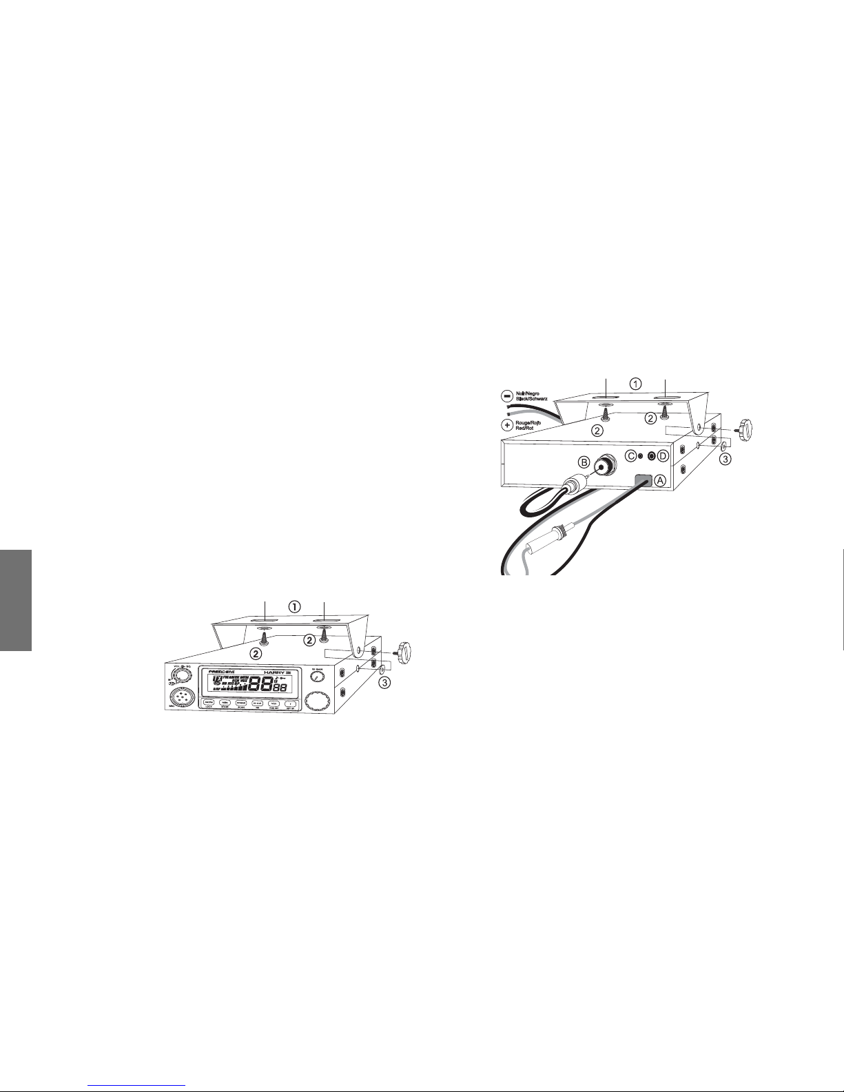
- For an antenna which must be fixed by drilling, you will need a good contact be-
tween the antenna and the ground plane. To obtain this, you should lightly scratch
the surface where the screw and tightening star are to be placed.
- Becareful not to pinchorflatten the coaxialcable(as this runstherisk of break down
and/or short circuiting).
- Connect the antenna (B).
c)Fixed antenna:
- A fixed antenna should be installed in a clear a space as possible. If it is fixed to a
mast,itwillperhapsbenecessarytostayit,
accordingtothelawsinforce(youshould
seek professional advice). All PRESIDENT
antennas and accessories are designed
to give maximum efficiency to each CB
radio within the range.
3) POWER CONNECTION
YourPRESIDENTHARRYIIIASC is protected againstaninversion of polarities. However,
beforeswitchingit on,youareadvisedto checkalltheconnections.Your equipment
mustbesuppliedwithacontinuedcurrentof 12 volts (A). Today,most cars and lorries
are negative earth. You can check this by making sure that the negative terminal
of the battery is connected either to the engine block or to the chassis. If this is not
the case, you should consult your dealer.
WARNING: Lorries generally have two batteries and an electrical installation of 24
volts,in which case itwill be necessarytoinsert a 24/12voltconverter (type CV24/12
PRESIDENT)intotheelectricalcircuit.Thefollowingconnectionstepsshouldbecarried
out with the power cable disconnected from the set.
a) Check that the battery is of 12 volts.
b) Locate the positive and negative terminals of the battery (+is red and -is black).
Should it be necessary to lengthen the power cable, you should use the same or a
superior type of cable.
c) Itis necessaryto connect your CB toa permanent (+)and (-). We advise youto con-
nect the power cable directly to the battery (as the connection of the CB cable to
the wiring of the car-radio or other parts of the electrical circuit may, in some cases,
increase the likelihood of interference).
d) Connect the red wire (+) to the positive terminal of the battery and the black (-)
wire to the negative terminal of
the battery.
e) Connectthepowercabletoyour
CB radio.
WARNING: Never replace the
original fuse (2 A) by one of a
different value.
English
33
4) BASIC OPERATIONS TO BE CARRIED OUT BEFORE USING YOUR
SET FOR THE FIRST TIME (without transmitting and without using
the «push-to-talk» switch on the microphone)
a) Connect the microphone
b) Check the antenna connections
c) Turn the set on by turning the volume knob (1) clockwise.
d) Turn the squelch SQ knob (2) to minimum (Mposition).
e) Adjust the volume to a comfortable level.
f) Go to channel 20 by using the channel selectors (5).
5) ADJUSTMENT OF SWR (Standing wave ratio)
WARNING: This must be carried out when you use your CB radio for the first time (and
whenever you re-position your antenna). The adjustment must be carried out in an
obstacle-free area.
* Adjustment with external SWR-meter (e.g. TOS-1 PRESIDENT)
a) To connect the SWR meter :
- Connectthe SWR meter betweenthe CB radio andthe antenna as closeas possible
to the CB (use a maximum of 40 cm cable, type President CA 2C).
b) To adjust the SWR meter:
- Set the CB to channel 20.
- put the switch on the SWR-meter to position CAL (calibration).
- Press the «push-to-talk» switch on the microphone to transmit.
- Bring the index needle to Wby using the calibration key.
- Change the switch to position SWR (reading of the SWR level). The reading on the
Metershould be as near as possible to 1.If this isnot the case,re-adjust your antenna
to obtain a reading as close as possible to 1. (An SWR reading between 1 and 1.8 is
acceptable).
- It will be necessary to re-calibrate the SWR meter after each adjustment of the
antenna.
WARNING: In order to avoid any losses and attenuations in cables used for connec-
tion between the radio and its accessories, PRESIDENT recommends to use a cable
with a length inferior to 3m.
Your CB is now ready for use.
B) HOW TO USE YOUR CB
1) ON/OFF – VOLUME
a) To turn the set on, turn the knob (1) clockwise.
b) To increase the sound level, turn the same knob further clockwise.
2) ASC (Automatic Squelch Control) / SQUELCH
Suppressesundesirablebackgroundnoiseswhenthereisnocommunication.Squelch
does not affect neither sound nor transmission power, but allows a considerable
improvement in listening comfort.
a) ASC: AUTOMATIC SQUELCH CONTROL
Worldwide patent, a PRESIDENT exclusivity.
TurntheSQknob(2)anti-clockwiseintoASCposition.«ASC»appearsonthedisplay.No
repetitivemanualadjustmentandapermanentimprovementbetweenthesensitivity
and the listening comfort when ASC is active. This function can be disconnected by
turning the switch clockwise. In this case the squelch adjustment becomes manual
again. «ASC» disappears from the display.
b) MANUAL SQUELCH
TurntheSQknobclockwisetotheexactpointwhereallbackgroundnoisedisappears.
This adjustment should be done with precision as, if set to maximum (fully clockwise),
only the strongest signals will be received.
English
34
3) DISPLAY
It shows all functions:
The BARGRAPH shows the reception level and the output power level.
4) RF GAIN
Adjustment of the sensitivity during reception. For long distance communications
RF GAIN should be set to maximum. You can reduce the RF GAIN in order to avoid
distortion when your correspondent is close by and when he has no RF POWER.
The normal setting of this function is on maximum (fully clockwise).
5) CHANNEL SELECTOR: Rotary Knob and UP/DN keys of the
microphone
This button allow increasing or decreasing a channel. A «beep» sounds each time
the channel changes if the KEY BP function is activated. See KEY BP function.
6) F ~ KEY BP
F - FREQUENCY BAND SELECTION
(configuration: E; d; EU; EC; U; PL)
The frequency bands have to be chosen according to the country of use. Don’t use
any other configuration. Some countries need a user’s licence.
See the configurations/ frequency bands table at page 53 to 56.
Proceeding: switch off the transceiver. Keep the key Fpressed and switch on again.
and the letter corresponding to the configuration are blinking.
- In order to change the configuration, use the channel selector on the front panel or
the UP/DN keys of the microphone.
- When the configuration is selected, press 1 second on the Fkey. and the letter
corresponding to the configuration are continuously displayed, a beep sounds. At
this point, confirm the selection by switching off the transceiver and then switching
it on again.
See table page 56.
KEY BP Beep on changing the channel, keys etc... (long press)
Activate the KEY BP function by pressing 1 second the KEY BP key. A beep sounds
and «BP» is displayed. In order to disable the function, press during 1 second the KEY
BP key. «BP» disappears.
7) VOX ~ VOX SET
VOX (short press)
The VOX function allows transmitting by speaking into the original microphone (or in
the optional vox microphone) without pressing the PTT switch. The use of an optional
vox mike connected to the rear panel of the transceiver (C) disables the original
microphone.
Press shortly the VOX key in order to activate the VOX function. «VOX» appears on
the display. A new press on the VOX key disables the function «VOX» disappears.
VOX SET (long press)
Press during 1 second the VOX key in order to activate the functionVox adjustment.
Threeadjustments are possible:Sensitivity / Anti-vox level /Voxdelay time . Press
English
35
shortly the VOX key in order to go to the following adjustment (looping , , ).
The display shows the type of adjustment followed by its level.
- Sensitivity : allows the adjustment of the microphone (original one or optional vox)
for an optimum transmission quality. Adjustable level from 1 (high level) to 9 (low
level) by rotating the channel knob. corresponds to the Sensitivity Level.
- Anti-Vox : allows disabling the transmission generated by the surrounding noise.
The level is adjustable from 0 (Off) to 9 (low level) by rotating the channel knob.
corresponds to Anti-vox Level.
- Delay time : allows avoiding the sudden cut of the transmission by adding a delay
at the end of speaking. The level is adjustable from 1 (short delay) to 9 (long delay)
by rotating the channel selector. corresponds to Delay Time.
Once the adjustments are done, press during 1 second the VOX key in order to quit
the Vox Adjustment mode.
8) HI-CUT ~ NB
HI-CUT (short press)
Eliminates high frequency interferences. Has to be used in accordance with
the reception conditions. «HIC» appears on the display when the HI-Cut filter is
activated.
NB (long press)
Noise Blanker. These filters allow reducing back ground noises and some reception
interferences. «NB» appears on the display when the NB filter is activated.
ANL FILTER (Automatic Noise Limiter)
The transceiver is equipped with an automatic filter which reduces back ground
noises and some reception interferences in AM.
9) ROGER ~ SCAN
ROGER (short press)
The icon « » appears on the display when the function is active. The Roger Beep
sounds when the PTT switch of the microphone is released in order to let your cor-
respondent speak. Historically as CB is a «simplex» communication mode, it is not
possible to speak and to listen at the same time (as it is the case with a telephone).
Once someone had finished talking, he said “Roger” in order to prevent his cor-
respondent that it was his turn to talk. The word “Roger” has been replaced by a
significant beep. There comes “Roger beep” from.
Note: the Roger beep also sounds in the loudspeaker if the KEY BP function is active.
Ifthe KEY BP functionis not active, only thecorrespondent can hear the Roger Beep.
SCAN (long press)
Channel research: Allowsactivating theSCAN function (research of thechannels) in
an increasing way. «SCN» is displayed. The scanning stops as soon as there is a busy
channel.Thescanningautomaticallystarts3secondsaftertheendofthetransmission
and no key is activated during 3 s. The scanning starts again in an increasing way
by turning the rotary knob to the right or pressing the UP key of the microphone, or
in a decreasing way by turning the rotary knob to the left or pressing the DN key of
the microphone.
A new long press on SCAN disables the SCAN function.
10) STORE ~ MEM
STORE
(long press)
Allows to memorize an emergency channel with following parameters: AM (except
for EC and Uconfigurations) or FM (and CEPT/ENG in Uconfiguration); NB; HI-CUT.
English
36
To memorize: Select the channel to be memorized.
- press 1 second the MEM key; «MEM» appears in the display. If the KEY BP function is
activated a long beep confirms the saving.
To delete a memory:
- switch off the transceiver.
- keep the MEM key pressed and switch on the transceiver.
- the memory is deleted.
MEM (short press)
To recall a memory:
- press MEM shortly, «MEM» appears on the display. If the KEY BP function is activated
a beep sounds. The memorized channel is actived.
11) AM/FM ~ LOCK
AM/FM
This switch allows selecting the AM or FM modulation. Your modulation mode has to
correspond to the one of your correspondent.
Amplitudemodulation/AM:isforcommunicationsinareaswherethereareobstacles
and over medium distances.
Frequency modulation/FM: for nearby communications in flat, open field.
LOCK
Allows to lock all the keys on the front pannel, the rotary knob and UP/DN keys on
the microphoe. An error beep sounds when a key is used and the LOCK function
is activated. A short press on LOCK activates/deactivates the LOCK function.
appears on the display when the function is activated.
Transmission (mike or vox) and reception remain active.
12) 6 PIN MICROPHONE PLUG
The plug is located on the front panel of the transceiver and makes the setting of
the equipment into the dashboard easier.
See cabling diagram page 55.
13) PTT
Transmission key, press to transmit a message, is displayed and release to listen
to an incoming communication.
A) DC-POWER TERMINAL (13,2 V)
B) ANTENNA CONNECTOR (SO-239)
C) JACK FOR OPTIONAL VOX MIKE (Ø 2.5 mm)
D) EXTERNAL SPEAKER JACK (8 Ω, Ø 3,5 mm)
English
37