truflo TSMP Series Instruction manual

Installation,
Operation, &
Maintenance
Manual
A New Vision For Quality Pumps
TSMP Series

2Revision8–November2011
We, at Truflo, would like to thank you for buying our high quality equipment and want
you to know that we are committed to you with this purchase and long term as a satisfied
customer. We know that you can buy form any Manufacturer, but we want you
convinced that we are the only real true supplier that is on your team.
The following is the IOM, (Installation, Operation, and Maintenance manual for Truflo pumps, TSMP, process
Pump designed to API* Standard 610 10th Edition (ISO13709). We cover the standard product plus common
options that are available. For special options, additional instructions are added. Please read complete manual
before installation and maintenance.
The quality design, materials, and workmanship used in the construction of all TRUFLO Pumps, gives these
units long lasting service. The life and satisfactory service of any mechanical unit, however, is enhanced and
extended by correct application, proper installation, inspection, monitoring and consistent maintenance. This
instruction manual was prepared to assist you in understanding the construction and the correct methods of
installing, operating, and maintaining these pumps.
Warranty is valid only when genuine TRUFLO parts are used.
Use of the equipment on a service other than stated in the order will nullify the warranty, unless written approval
is obtained in advance from Truflo Pumps.
Supervision by an authorized Truflo Pumps representative is recommended to assure proper installation.
THIS MANUAL EXPLAINS
Ordering Spare or Repair Parts
Troubleshooting
Pump Overhaul
Operation Procedures
Routine Maintenance
Start-up Procedures
Installation
Additional manuals can be obtained by contacting your local Industries -Truflo Pumps representative, by
calling 1-336-664-9225, or visiting our website at www.truflo.com.
* American Petroleum Institute
1220 L Street, Northwest
Washington, D.C. 20005

Revision8–November20113
PAGE SECTION

4Revision8–November2011
IMPORTANT SAFETY NOTICE
User safety is a major focus in the design of our products. Following
the precautions outlined in this manual will minimize your risk of
in
j
ur
y
.
Truflo pumps will provide safe, trouble-free service when properly
installed, maintained, and operated.
Safe installation, operation, and maintenance of Truflo Pumps equipment
are a critical end user responsibility. This Pump Safety Manual identifies
specific safety risks that must be considered at all times during product life.
Understanding and following these safety warnings is mandatory to ensure
p
eople, property, and/or the environment will not be harmed. Following
these warnings alone, however, is not sufficient it is anticipated that the end
user will also comply with industry and corporate safety standards.
Please take the time to review and understand the safe installation,
operation, and maintenance guidelines outlined in this Pump Safety Manual
and the Instruction, Operation, and Maintenance (IOM) manual. Current
manuals are available at www.truflo.com or by contacting your nearest
Truflo Pumps sales representative.
For additional information, contact your nearest Truflo Pumps sales representative or visit our
Web site at www.truflo.com, or call us at 336-664-9225.

Revision8–November20115
SAFETY WARNINGS
WARNING
A pump is a pressure vessel with rotating parts that can be hazardous. Any pressure vessel can explode,
rupture, or discharge its contents if sufficiently over pressurized causing death, personal injury, property
damage, and/or damage to the environment. All necessary measures must be taken to ensure over
pressurization does not occur. Please review all pages of this manual.
WARNING
N
ever operate a pump with a blocked suction and discharge, this must be avoided in all cases, even for a brief
period under these conditions, this will cause superheating of enclosed pumped fluid and result in a violent
explosion. All necessary measures must be taken by the end user to ensure this condition is avoided.
WARNING
The pump may handle hazardous and/or toxic fluids. Care must be taken to identify the contents of the pump
and eliminate the possibility of exposure, particularly if hazardous and/or toxic. Potential hazards include, but
are not limited to, high temperature, flammable, acidic, caustic, explosive, and other risks.
WARNING
Pumping equipment Instruction, Operation, and Maintenance manuals identify accepted methods for
disassembling pumping units. All these methods must be adhered to. Specifically, applying heat to impellers
and/or impeller retaining devices to aid in their removal is strictly forbidden. Trapped liquid can rapidly
expand and result in a violent explosion and injury.
Truflo Pumps will not accept responsibility for physical injury, damage, or delays caused
by a failure to observe the instructions for installation, operation, and maintenance
contained in this Pump Safety Manual or the current IOM available at www.truflo.com.

6Revision8–November2011
SAFETY
DEFINITIONS
Throughout this manual the words WARNING, CAUTION, and ELECTRICAL, are used to indicate where
special operator attention is required, please pay caution.
WARNING
Indicates a hazardous situation, which if not avoided could result in death or serious injury.
Example: Never operate a pump without coupling guard installed correctly. Never run dry.
Never run with no suction are a few examples.
CAUTION
Indicates a hazardous situation, which if not avoided could result in minor or major injury.
ELECTRICAL HAZARD
Indicates the possibility of electrical risks if directions are not followed. Example: Lock out driver
power to prevent electric shock, accidental start-up, and physical injury.
When installed in potentially explosive atmospheres, the instructions that follow the Ex symbol must be
followed. Personal injury and/or equipment damage may occur if these instructions are not followed. If there
is any question regarding these requirements or if the equipment is to be modified, please contact a Truflo Pumps
representative before proceeding.

Revision8–November20117
GENERAL PRECAUTIONS
WARNING
A pump is a pressure vessel with rotating parts that can be hazardous. Hazardous fluids may be contained by
the pump including high temperature, flammable, acidic, caustic, explosive, and other risks. Operators and
maintenance personnel must realize this and follow safety measures. Personal injuries will result if procedures
outlined in this manual are not followed. Truflo Pumps will not accept responsibility for physical injury, damage
or delays caused by a failure to observe the instructions in this manual and the IOM provided with your
equipment.
General Precautions
NOTE NEVER HEAT TO REMOVE IMPELLER. It may explode due to trapped
liquid.
NOTE NEVER use heat to disassemble pump due to risk of explosion from tapped liquid.
NOTE NEVER operate pump without coupling guard correctly installed.
NOTE NEVER run pump below recommended minimum flow when dry, or without
prime.
NOTE ALWAYS lock out power to the driver before performing pump maintenance.
NOTE NEVER operate pump without safety devices installed.
NOTE NEVER operate pump with discharge valve closed.
NOTE NEVER operate pump with suction valve closed.
NOTE DO NOT change service application without approval of an authorized Truflo
Pumps representative.
NOTE
Safety Apparel: Insulated work gloves when handling hot bearings or using
bearing heater , Heavy work gloves when handling parts with sharp edges,
especially impellers Safety glasses (with side shields) for eye protection Steel-toed
shoes for foot protection when handling parts, heavy tools, etc. Other personal
protective equipment to protect against hazardous/toxic fluids.
NOTE
Receiving: Assembled pumping units and their components are heavy. Lift
properly and support equipment, neglect can result in serious physical injury
and/or equipment damage. Lift equipment only at specifically identified lifting
points or as instructed in the current IOM. Current manuals are available at
www.truflo.com or contact your local Truflo Pumps sales representative. Note:
Lifting devices (eyebolts, slings, spreaders, etc.) must be rated, selected, and used
for the entire load being lifted.
WARNING Alignment: Shaft alignment procedures must be followed to prevent catastrophic
failure of drive components or unintended contact of rotating parts. Follow
coupling manufacturer’s coupling installation and operation procedures.

8Revision8–November2011
General Precautions
NOTE Before beginning any alignment procedure, make sure driver power is locked out.
Failure to lock out driver power will result in serious physical injury.
NOTE
Piping: Never pull piping into place by forcing at the flanged connections of the
pump. This may impose dangerous strains on the unit and cause misalignment
between pump and driver. Pipe strain will adversely affect the operation of the
pump resulting in physical injury and damage to the equipment.
NOTEFlanged Connections: Use only fasteners of the proper size and material.
NOTEReplace all corroded fasteners.
NOTEEnsure all fasteners are properly tightened and there are no missing fasteners.
NOTE
Startup and Operation: When installing in a potentially explosive environment,
please ensure that the motor is certified explosion proof.
NOTEDo not operate pumps in reverse rotation may result in contact of metal parts, heat
generation, and breach of containment.
NOTELOCK out Tag out drivers
NOTEThe impeller clearance setting procedure must be followed. Improperly setting the
clearance or not following any of the proper procedures can result in sparks,
unexpected heat generation and equipment damage.
NOTEIf using a cartridge mechanical seal, the centering clips must be installed and set
screws loosened prior to setting impeller clearance. Failure to do so could result
in sparks, heat generation, and mechanical seal damage.
NOTEThe coupling used in an ATEX classified environment must be properly certified
and must be constructed from a non-sparking material.
NOTENever operate a pump without coupling guard properly installed. Personal injury
will occur if pump is run without coupling guard.
NOTEProperly lubricate the bearings. Failure to do so may result in excess heat
generation, sparks, and / or premature failure.
NOTEThe mechanical seal used in an ATEX classified environment must be properly
certified. Prior to start up; ensure points of potential leakage of process fluid to the
work environment are closed.
NOTEDo not operate the pump without liquid supplied to mechanical seal. Running a
mechanical seal dry, even for a few seconds, can cause seal damage and must be
avoided. Physical injury can occur if mechanical seal fails.
NOTENever attempt to replace packing until the driver is properly locked out and the
coupling spacer is removed.
NOTEDynamic seals are not allowed in an ATEX classified environment.
NOTEDO NOT operate pump below minimum rated flows or with suction and/or
discharge valve closed. These conditions can create an explosive and hazardous to
vaporization of pumped fluid and can quickly lead to pump failure and physical
injury.

Revision8–November20119
General Precautions
NOTEEnsure pump is isolated from system and pressure is relieved before
disassembling pump, removing plugs, opening vent or drain valves, or
disconnecting piping.
NOTEShutdown, Disassembly, and Reassembly: Pump components can be heavy.
Please lift properly to avoid physical injury and/or equipment damage. Steel toed
shoes must be worn at all times.
NOTEThe pump may handle hazardous and/or toxic fluids. Observe proper
decontamination procedures. Proper personal protective equipment should be
worn. Precautions must be taken to prevent physical injury. Pumped fluid must be
handled and disposed of in conformance with applicable environmental
regulations.
NOTEOperator must be aware of pumped fluid and safety precautions to prevent
physical injury.
NOTE
Lock Out Tag Out.
NOTEAllow all system and pump components to cool before handling them to prevent
physical injury.
NOTE
There may be a risk of static electric discharge from plastic parts that are not
properly grounded. If pumped fluid is non-conductive, pump should be drained
and flushed with a conductive fluid under conditions that will not allow for a
spark to be released to the atmosphere.
NOTENever apply heat to remove an impeller. The use of heat may cause an explosion
due to trapped fluid, resulting in severe physical injury and property damage.
NOTEWear heavy work gloves when handling impellers as sharp edges may cause
physical injury.
NOTEWear insulated gloves when using a bearing heater. Bearings will get hot and can
cause physical injury.

10Revision8–November2011
The use of genuine Truflo parts will provide the safest and most
reliable operation of your pump. Truflo Pumps certification and
quality control procedures ensure the parts are manufactured to
the highest quality and safety levels. Quality parts are extremely
important for original, Fit, Form and Function for continued
long term, and safe operation. Please do not use non OEM parts
as warranties will be voided.
II = Group 2
2 = Category 2
G/D = Gas and Dust present
T4 = Temperature class, can be T1 to T6 (see Table 1)
The code classification marked on the equipment must be in accordance with the specified area where the
equipment will be installed. If it is not, do not operate the equipment and contact your Truflo Pumps sales
representative before proceeding.
Table 1
Code
Max permissible
surface temperature oF
(oC)
Max permissible
liquid temperature
oF (oC)
T1 842 (450) 700 (372)
T2 572 (300) 530 (277)
T3 392 (200) 350 (177)
T4 275 (135) 235 (113)
T5 212 (100) Option not available
T6 185 (85) Option not available

Revision8–November2011
11
Transportation and Storage
Receive the unit
Unpack the unit
Pump handling
WARNING:
Make sure that the pump cannot roll or fall over and injure people or damage property.
NOTICE: Use a forklift truck with sufficient capacity to move the pallet with the pump unit on top.
Failure to do so may result in equipment damage.
Lifting methods
WARNING:
•Assembled pumping units and their components are heavy. Failure to properly lift and
support this equipment can result in serious physical injury and/or equipment damage. Lift
equipment only at the specifically identified lifting points. Lifting devices such as eyebolts, slings,
and spreaders must be rated, selected, and used for the entire load being lifted.
•The pump and the components are heavy. Use proper lifting methods, and wear steel-toed
shoes at all times. Failure to do so can result in physical injury.
1Inspect the package for damaged or missing items upon delivery.
2Note any damaged or missing items on the receipt and freight bill.
3File a claim with the shipping company if anything is out of order.
1Remove packing materials from the unit. Dispose of all packing materials correctly.
2Inspect the unit to determine if any parts have been damaged or are missing.
3Contact your TRUFLO representative if anything seems out of order.
Warning: Do not attach sling ropes to shaft ends. Doing so may result in equipment damage.

12Revision8–November2011
Examples
Figure 1: Proper lifting method
Figure 2: Proper lifting method

Revision8–November2011
13
Figure 3: Proper lifting method
Pump storage requirements
Storage requirements are dependent on the amount of time the pump is stored. The normal packaging is
designed only to protect the pump during shipping.
Treat bearing and machined surfaces so that they are well preserved. Refer to drive unit and coupling
manufacturers for their long-term storage procedures. You can purchase long-term storage treatment with the
initial pump order or you can purchase it and ap
p
ly it after the pumps are already in the field. Contact your local
TRUFLO sales representative.
•Store in a covered and dry location.
•Store the unit free from dirt and vibrations.
•Store in a covered and dry location.
•Store the unit free from heat, dirt, and vibrations.
•Rotate the shaft by hand several times at least every three months.

14Revision8–November2011
PUMPDESCRIPTION 14
N
AMEPLATE INFORMATION 15
RECEIVINGTHEPUMP 16
PUMP DESCRIPTION
The Model TSMP is a high pressure, multi-stage, between
the bearings, horizontal centrifugal pump designed to meet
the rigorous demands of the petroleum and petrochemical
market place. It is in full compliance with API 610 10th
Edition (ISO 13709).
Casing -The casing is mounted with side suction and side
discharge nozzles. ANSI class 900+ (Higher flange options
available) pound raised face serrated flanges with a
125-250 rims finish are standard. 600 and 1500 pound and
ring type joint (RTJ) flanges are available options.
Impeller -The impeller is a fully closed design and is
keyed.
Seal Chamber -The Model TSMP has a seal chamber
designed in accordance with API 682 2nd Edition criteria.
Customer selected cartridge mechanical seals are standard.
Bearing Housings -Ductile iron bearing housings are
standard on non-API services and carbon steel on API
services. Oil level is viewed through a sight glass. Constant
level oilers and labyrinth seals are standard. No machining
is required to convert the standard ring oil lube to either
purge or pure mist, although pure mist applications require
minor bearing housing modifications. Pressure lubrication is
required with hydrodynamic thrust bearings.
Shaft -The heavy duty shaft is designed for cartridge
mechanical seals, minimal shaft deflection at the seal faces
(.002) when run in the worst case condition (typically
minimum flow), and a critical speed at least 20% above
design operating speed. Fully compliant with API 10th
Edition (ISO 13709).
Bearings -Radial loads are carried by a single row, deep
groove ball bearing (standard) or sleeve bearings
(optional). The axial thrust load is handled by a pair of
single row angular contact ball bearings mounted back to
back (standard), or a hydrodynamic thrust bearing (used
with sleeve type journal bearings). When ball bearings are
used (standard), the outboard bearing (thrust bearing) is
shouldered and locked into place, thus enabling it to carry
both radial and axial thrust loads. All fits are precision
machined to both the shaft and bearing housing to industry
standards. Size 6x8-13 pumps come standard with
sleeve/ball bearing arrangement.
Baseplate -The fabricated steel baseplate is designed to
support the pump, driver and accessories in accordance
with API 10th Edition (ISO 13709) requirements.
Direction of Rotation -Counterclockwise (left hand) as
viewed from the driver, looking at the pump shaft. (Check
with the factory for clockwise rotation.)

Revision8–November2011
15
NAMEPLATE INFORMATION
Our Pumps have a Truflo nameplate that provides all necessary pump information you will need to identify information
about the pump. The nameplate is located on model, size, serial number, and the item number of the pump casing.
Required parts. Information can be taken from the pump casing tags. Item numbers can be found later on in this manual.
Description Fig. No. Example
Pump Casing Tag -provides information
about the pump’s hydraulic
characteristics. Note the format of the
pump size: Discharge x Suction -Nominal
maximum Impeller Diameter in inches.
(Example: 2x3-8) (Figs.1&2).
Fig. 1
English
Fig. 2
Metric

16Revision8–November2011
RECEIVING THE PUMP
Inspect the pump as soon as it is received. Carefully check
that everything is proper. Make notes of damaged or
missing items on the receipt and freight bill. File any claims
with the transportation company as soon as possible.
STORAGE REQUIREMENTS
Short Term (Less than 6 months) Truflo normal
packaging procedure is designed to protect pump during
shipping. Upon receipt, store in a covered and dry location.
Long Term (More than 6 months) Preservative treatment
of bearings and machined surfaces will be required. Rotate
shaft several times every 3 months. Refer to driver and
coupling manufacturers for their long term storage
procedures. Store in a covered and dry location.
HANDLING
Use care when moving pumps. Lifting equipment must be
able to adequately support the entire assembly. Hoist bare
pump using suitable slings under the suction flange and
discharge flange (Fig. 4). Baseplate mounted units are
provided with lifting points for use with proper lifting
devices. Refer to (Fig.5&6) for examples of proper lifting
procedures.
�! WARNING
Pump and components are heavy. Failure to properly
lift and support equipment could result in serious
physical injury or damage to pumps.

Revision8–November2011
17
SITE/FOUNDATION 17
GENERAL 17
BASEPLATE INSTALLATION PROCEDURE 18
BASEPLATE PREPARATION 18
FOUNDATION PREPARATION 18
SETTING AND LEVELING BASEPLATE 18
ALIGNMENT AND ALIGNMENT CRITERIA 19
GENERAL CONSIDERATIONS 19
ALIGNMENTCRITERIA 20
PUMP-TO-DRIVER ALLIGNMENT 20
ALIGNMENT TROUBLESHOOTHING 25
BASEPLATE GROUTING PROCEDURE 26
GENERALPROCEDURE 26
ALIGNMENTCHECK 27
PIPING 27
SUCTIONPIPING 27
DISCHARGEPIPING 27
BYPASSPIPING 27
AUXILIARYPIPING 29
FINAL PIPING CHEC
K
29
SITE AND FOUNDATION
GENERAL INFORMATION
Procedures for installation described in this section are
general. More detailed procedures are described in various
publications including API Recommended Practice
686/PIP (Process Industry Practices) REIE 686,
"Recommended Practices for Machinery Installation and
Installation Design." A pump should be located near the
liquid supply and have adequate space for operation,
maintenance, and inspection. Be sure to allow for crane or
hoist service.
Baseplate mounted pumps are normally grouted on a
concrete foundation which has been poured on a solid
footing. The foundation must be able to absorb any
vibration and to form a permanent, rigid support for the
pumping unit.
All equipment being installed must be properly
g
rounded to prevent unexpected static electric
discharge.
The location and size of foundation bolts are shown on the
outline assembly drawing provided with the pump data
package.
Foundation bolts commonly used are sleeve type (Fig. 7)
and J type. If using the sleeve type, the inside diameter of
the sleeve should be 2 1/2 -3 times the bolt diameter. A
washer should be placed between the bolt and the sleeve.
Both foundation bolt types permit movement for final bolt
adjustment.

18Revision8–November2011
BASEPLATE INSTALLATION PROCEDURE
Industry standard procedures, such as API RP 686/ PIP
REIE 686, and/or the following procedure should be
followed prior to grouting the baseplate. The procedure
assumes the installer has a basic knowledge of baseplate
and foundation design and installation methods.
BASEPLATE PREPARATION
1-Inspect all surfaces of baseplate that will contact grout for
contamination (e.g. -rust, oil, grime, etc.).
1- Thoroughly clean all surfaces of the baseplate that will
contact grout with a cleaner that will not leave any residue.
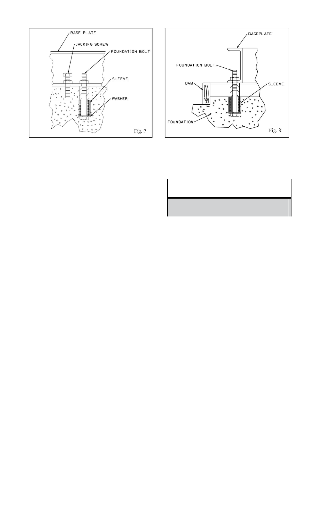
Remove water and/or debris from foundation bolt
holes/sleeves. If the sleeve type bolts are being
used, fill the sleeves with nonbinding moldable
material and seal to prevent grout from entering.
Coat exposed portion of anchor bolts with a
non-bonding compound (such as paste wax) to
prevent grout from adhering to anchor bolts.
2-Inspect all machined surfaces for burrs, rust, paint or
any other type of contamination. If necessary, use a
honing stone to remove burrs.
Chip top of foundation a minimum of 25 mm) to
remove porous or low strength concrete. If using a
pneumatic hammer, assure that it is not contaminating
the surface with oil, moisture, etc
If recommended by grout manufacturer,
coat foundation surface with a
compatible primer.
3-Coat portions of leveling screws that will contact grout
with a non-bonding (anti-seize) compound (such as paste
wax) to facilitate their removal after grouting.
4-Thread nuts on foundation bolts and hand tighten.
FOUNDATION PREPARATION
SETTING AND LEVELING BASEPLATE
Lower base onto foundation bolts. Base will rest
on top of foundation on jackscrews provided on
base (Figs. 9 & 10).
Adjust leveling jack screws, located adjacent to
the foundation bolt holes, until the baseplate rests
1-2 in. (25 -50 mm) above foundation to allow for
adequate grouting. This will provide even support
for the base once it is grouted.
Level base to within .002 in./ft. (0.20 mm/m) of
length or width of the base, respectively, by
adjusting leveling screws. Maximum total
variation from one end or side of the base to the
other is .015 in. (0.38 mm).
�CAUTION
Do not use heavy tools such as jackhammers, as they
could damage the structural integrity of the
foundation.

Revision8–November2011
19
Equipment mounting surfaces should be utilized to
establish level.
ALIGNMENT AND ALIGNMENT CRITERIA
Alignment procedures must be followed to prevent
unintended contact of rotating parts. Follow coupling
manufacturer's installation and operation procedures.
• After First Run -To obtain correct alignment when
both pump and driver are at operating temperature.
Thereafter, alignment should be checked periodically in
accordance with plant operating procedures.
N
OTE: Ali
g
nment check must be made i
f
process
temperature changes, piping changes, and/or pump
s
ervice is per
f
ormed.
Alignment is achieved by adding or removing shims from
under the driver and/or shifting driver horizontally as
needed.
Final Alignment (Hot Alignment) is done after operation
when the pump and driver are at operating temperatures.
N
OTE: Proper ali
g
nment is the responsibilit
y
of the installer and user of the unit.
Accurate alignment of the equipment must be attained.
Trouble-free operation can be accomplished by achieving
alignment within the levels specified in the following
section.
Three common alignment methods are utilized:
1-Reverse Dial Indicator method is most common.
2-Laser method is similar to reverse dial indicator
method, but uses a laser to obtain the necessary
measurements.
3-Dial Indicator (rim-and-face) method.
GENERAL CONSIDERATIONS
To remove coupling guard, refer to coupling guard
installation and disassembly instructions in Appendix
II
.
Initial Alignment (Cold Alignment) is done prior to
operation when the pump and the driver are at ambient
temperatures.
1-Before Grouting Baseplate -To ensure alignment can be
obtained.
2-After Grouting Baseplate -To ensure pipe strains haven’t
altered alignment. If changes have occurred, alter piping to
remove pipe strains on pump flanges.
Follow alignment equipment manufacturers’ procedures
when utilizing reverse dial indicator or laser methods. A
detailed procedure for alignment using the dial indicator
(rim-and-face) method is included as Appendix III.

20Revision8–November2011
ALIGNMENT CRITERIA
Good alignment is attained when readings as specified in
this section have been achieved with pump and driver at
operating temperatures (final alignment).
Maximum allowable Total Indicator Reading
(T.I.R.) for parallel and angular misalignment is
.002 (0.05mm) for all Model TSMP pumps,
regardless of the alignment method used.
Pump-to-driver alignment
Precautions
Follow the equipment manufacturer's instructions when using the reverse dial indicator or laser
methods. Detailed instructions for using the dial indicator method are contained in this section.
Alignment checks
When to perform alignment checks
Alignment checks must be performed when the following occurs:
•The process temperature changes.
•The piping changes.
•The pump has been serviced.
WARNING:
•Follow shaft alignment procedures to prevent catastrophic failure of drive components or
unintended contact of rotating parts. Follow the coupling manufacturer’s coupling installation and
operation procedures.
•ALWAYS lock out power to the driver before performing any installation or maintenance
tasks. Failure to lock out driver power will result in serious physical injury.
NOTICE: Proper alignment is the responsibility of the installer and the user of the unit. You must
check the alignment of frame-mounted units before the unit is operated. Failure to do so may result in
equipment damage or decreased performance.
Alignment methods
Three common alignment methods are used:
•Dial indicator
•Reverse dial indicator
•Laser
Final alignment (hot
alignment)check After operation when the pump and the driver are at operating
temperature.
Prior to operation when the pump and the driver are at ambient
temperature.
Initial alignment (cold
alignment)check
Types of alignment checks Type of check
Table of contents
Other truflo Water Pump manuals
Popular Water Pump manuals by other brands

DÖRR
DÖRR EcoPump VP 55 200 DE Operation manual

Pentair Pool Products
Pentair Pool Products Hydromatic S4HRC Service manual

Blue-White
Blue-White FlexFlo A-1600 Series manual

AQUASYSTEM
AQUASYSTEM AMH1-25FC Operation manual

BUSCH
BUSCH COBRA NX 0950 A PLUS instruction manual

PVR
PVR EU W Series Operating maintenance instructions & part list

Ingersoll-Rand
Ingersoll-Rand MP PUMPS CHEMFLO 4 56C Operator's manual

Clean Track
Clean Track Pump Series operating instructions

MATALA
MATALA MEA Pro Mini 2000 installation instructions

Meec tools
Meec tools 731104 operating instructions

BUSCH
BUSCH COBRA NC 1500 B Installation and maintenance instructions

esotec
esotec Napoli LED instruction manual