PREVOST H3-41 User manual

COACH MANUFACTURER
MAINTENANCE MANUAL
H3-41, H3-45, VIP
PA1217
(5th edition)

SECTION 26: VIP SLIDE-OUT
CONTENTS
1SLIDE-OUT .............................................................................................................................................. 5
1.1 INNER STOPPER ............................................................................................................................... 5
1.1.1 Maintenance ........................................................................................................................... 5
1.1.2 Adjustment ............................................................................................................................. 5
1.2 "IN LIMIT" STOPPER .......................................................................................................................... 5
1.2.1 Maintenance ........................................................................................................................... 6
1.2.2 Adjustment ............................................................................................................................. 6
1.3 EXTERIOR EXTRUSION .................................................................................................................... 6
1.3.1 Maintenance ........................................................................................................................... 6
1.3.2 Removal ................................................................................................................................. 6
2SECURITY PIN ........................................................................................................................................ 7
2.1 MAINTENANCE .................................................................................................................................. 7
2.2 AIR CYLINDER REPLACEMENT ....................................................................................................... 7
3ROOF REINFORCING ROD ................................................................................................................... 7
4RACK ....................................................................................................................................................... 8
4.1 MAINTENANCE .................................................................................................................................. 8
4.2 FRONT SLIDE-OUT RACK REPLACEMENT ..................................................................................... 8
4.3 REAR SLIDE-OUT RACK REPLACEMENT ....................................................................................... 8
5PINION ..................................................................................................................................................... 9
5.1 PINION AND KEYLESS BUSHING POSITIONING ............................................................................ 9
5.2 FRONT SLIDE-OUT SHAFT PINION REPLACEMENT ...................................................................... 9
5.3 REAR SLIDE-OUT SHAFT PINION REPLACEMENT ...................................................................... 10
5.4 KEYLESS BUSHING ........................................................................................................................ 10
5.4.1 Installation ............................................................................................................................ 10
6ELECTRIC MOTOR ............................................................................................................................... 13
6.1 MAINTENANCE ................................................................................................................................ 13
6.2 REPLACEMENT ............................................................................................................................... 13
7SPEED REDUCTION GEARBOX ......................................................................................................... 13
7.1 MAINTENANCE ................................................................................................................................ 13
7.2 GEARBOX REPLACEMENT ............................................................................................................ 13
8JAW COUPLING ................................................................................................................................... 14
8.1 MAINTENANCE ................................................................................................................................ 14
8.2 REPLACEMENT & ADJUSTMENT ................................................................................................... 14
9FLANGE BEARING ............................................................................................................................... 14
10 LOCKING COLLAR .............................................................................................................................. 14
10.1 INSTALLATION ............................................................................................................................. 15
11 LINEAR BEARING ................................................................................................................................ 15
11.1 MAINTENANCE ............................................................................................................................ 15
11.2 REPLACEMENT & ADJUSTMENT ............................................................................................... 15
11.3 LEVEL & TILT ADJUSTMENT ....................................................................................................... 15
11.3.1 Procedure ............................................................................................................................. 15
PA1217 1

Section 26: VIP SLIDE-OUT
12 RAIL ....................................................................................................................................................... 16
12.1 MAINTENANCE ............................................................................................................................ 17
12.2 REPLACEMENT ........................................................................................................................... 17
13 ACETAL PLASTIC BLOCKS ................................................................................................................ 17
13.1 REMOVAL / INSTALLATION ........................................................................................................ 17
14 SLIDE-OUT PNEUMATIC SYSTEM ..................................................................................................... 18
14.1 DESCRIPTION .............................................................................................................................. 18
14.2 MAINTENANCE ............................................................................................................................ 19
14.3 SEAL ............................................................................................................................................. 20
14.3.1 Maintenance ......................................................................................................................... 20
14.3.2 Seal assembly removal ........................................................................................................ 21
14.3.3 Seal assembly installation .................................................................................................... 21
14.3.4 Slide-out 2" inside retraction ................................................................................................ 22
15 SLIDE-OUT ELECTRICAL SYSTEM .................................................................................................... 22
15.1 ELECTRICAL INTERCONNECTION WITH PREVOST VEHICLE ............................................... 23
15.2 SLIDE-OUT BREAKERS .............................................................................................................. 23
15.3 PROBING VOLTAGE ON THE MULTIPLEX CIRCUITS .............................................................. 23
15.4 MODULE REPLACEMENT ........................................................................................................... 23
15.5 SLIDE-OUT LIMIT SENSORS ....................................................................................................... 23
15.5.1 Maintenance and adjustment ............................................................................................... 24
16 SLIDE-OUT EXTERIOR FINISHING PANELS & WINDOWS .............................................................. 25
16.1 FACE PANEL REMOVAL .............................................................................................................. 25
16.2 FACE PANEL INSTALLATION ...................................................................................................... 25
16.3 SIDE PANEL REMOVAL ............................................................................................................... 25
16.4 SIDE PANEL INSTALLATION ....................................................................................................... 26
16.5 TOP AND BOTTOM PANEL REMOVAL ....................................................................................... 27
16.6 TOP AND BOTTOM PANEL INSTALLATION ............................................................................... 28
16.7 SIDE WINDOW & HALF-WINDOW REMOVAL ............................................................................ 29
16.8 HALF-WINDOW & SIDE WINDOW INSTALLATION .................................................................... 30
16.9 FACE WINDOW INSTALLATION .................................................................................................. 31
16.10 AWNING WINDOW INSTALLATION ............................................................................................ 32
16.11 SLIDING WINDOW INSTALLATION ............................................................................................. 34
16.12 FINISHING JOINT ......................................................................................................................... 35
17 WELDING PRECAUTION ..................................................................................................................... 37
18 SLIDE-OUT MANUAL OVERRIDE PROCEDURES ............................................................................. 37
18.1 PRELIMINARY CONDITIONS FOR MANUAL OVERRIDE PROCEDURE ................................. 37
18.1.1 Manual retracting procedure – Front and rear slide-out ...................................................... 37
18.1.2 Manual extending procedure – Front and rear slide-out ...................................................... 39
19 SLIDE-OUT MAXIMUM LOAD .............................................................................................................. 40
20 CONVERSION CHECKLIST ................................................................................................................. 41
21 TROUBLESHOOTING .......................................................................................................................... 42
21.1 ERROR CONDITION OR MISSING OPERATION CONDITION ................................................... 42
21.2 TROUBLESHOOTING – OPERATING CONDITIONS & CONTROL ............................................ 42
21.3 TROUBLESHOOTING - MECHANICAL COMPONENTS ............................................................. 45
21.4 SLIDE-OUT FAULT MESSAGE ON MESSAGE CENTER DISPLAY (MCD) ................................ 48
PA1217 2

Section 26: VIP SLIDE-OUT
LIST OF ILLUSTRATIONS
FIGURE 1 : FRONT SLIDE-OUT ........................................................................................................................... 5
FIGURE 2 : REAR SLIDE-OUT ............................................................................................................................. 5
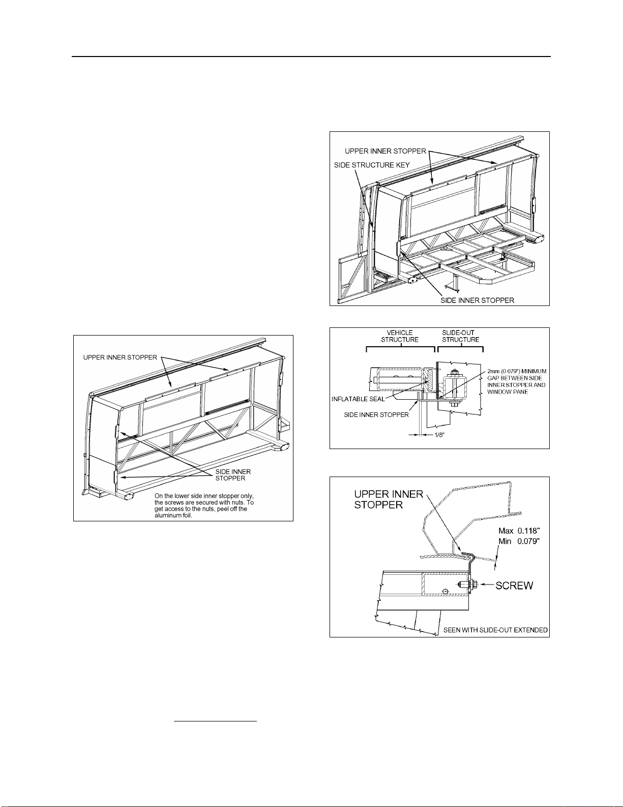
FIGURE 3 : SIDE INNER STOPPER ADJUSTMENT .................................................................................................. 5
FIGURE 4: UPPER INNER STOPPERS ADJUSTMENT .............................................................................................. 5
FIGURE 5: LOWER "IN LIMIT" STOPPER ............................................................................................................... 6
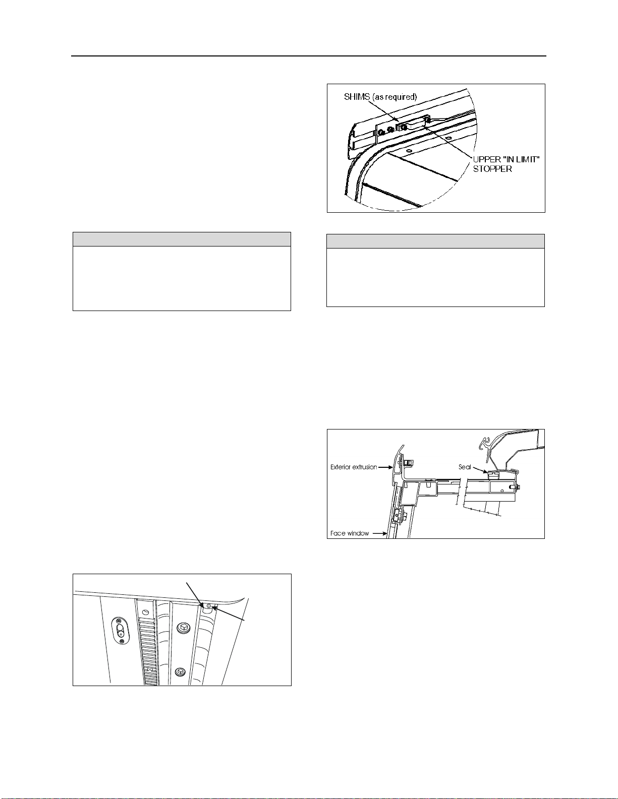
FIGURE 6: UPPER "IN LIMIT" STOPPER ............................................................................................................... 6
FIGURE 7 : EXTERIOR EXTRUSION ..................................................................................................................... 6
FIGURE 8: SECURITY PIN AIR CYLINDER REMOVAL .............................................................................................. 7
FIGURE 9 : FRONT SLIDE-OUT ROOF REINFORCING ROD ...................................................................................... 7
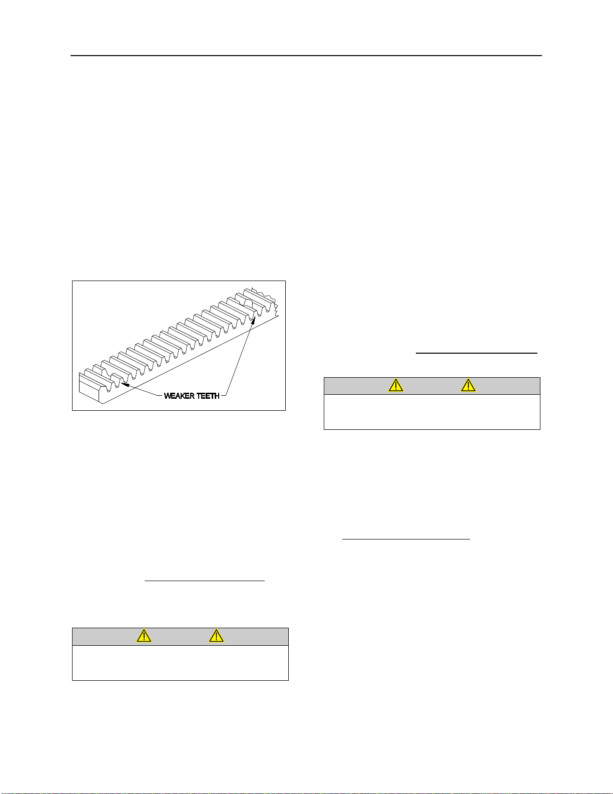
FIGURE 10 : RACK............................................................................................................................................ 8
FIGURE 11: PINION AND KEYLESS BUSHING POSITIONING .................................................................................... 9
FIGURE 12: PINION AND KEYLESS BUSHING (BOTTOM VIEW) ................................................................................ 9
FIGURE 13: MECHANICAL COMPONENTS (TYPICAL) ............................................................................................ 9
FIGURE 14 : KEYLESS BUSHING TIGHTENING .................................................................................................... 10
FIGURE 15 : TORQUE WRENCH FORMULA ........................................................................................................ 10
FIGURE 16 : KEYLESS BUSHING INSTALLATION INSTRUCTION ............................................................................ 12
FIGURE 17: ELECTRIC MOTOR AND SPEED REDUCTION GEARBOX ...................................................................... 13
FIGURE 18: MOTOR/GEARBOX ASSEMBLY MOUNTING BOLTS ............................................................................. 13
FIGURE 19: CLAMPING HUB POSITION ON SHAFTS ............................................................................................ 14
FIGURE 20: JAW COUPLING ............................................................................................................................ 14
FIGURE 21: SLIDE-OUT LEVEL ADJUSTEMENT ................................................................................................... 15
FIGURE 22 : SLIDE-OUT LEVELING ................................................................................................................... 16
FIGURE 23: TILT ADJUSTMENT ........................................................................................................................ 16
FIGURE 24 : RAIL POSITIONING ....................................................................................................................... 17
FIGURE 25: ACETAL PLASTIC BLOCKS .............................................................................................................. 17
FIGURE 26: REMOVE THE UPPER ACETAL PLASTIC BLOCKS WITH A PICKING TOOL ............................................... 17
FIGURE 27: LOWER ACETAL PLASTIC BLOCK INSERTION .................................................................................... 18
FIGURE 28 : FRONT SERVICE COMPARTMENT ................................................................................................... 19
FIGURE 29: PNEUMATIC CONTROL UNIT ........................................................................................................... 20
FIGURE 30 : SEAL ASSEMBLY .......................................................................................................................... 20
FIGURE 31: REAR SLIDE-OUT INFLATABLE SEAL AIR INLET ................................................................................. 20
FIGURE 32: WIPER SEAL CUT-OUT ................................................................................................................... 21
FIGURE 33: SLIDE-OUT 2" INSIDE – UPPER PART .............................................................................................. 22
FIGURE 34 : DASHBOARD SLIDE-OUT TELLTALE LIGHT ...................................................................................... 23
FIGURE 35: MAIN BREAKER IN MAIN POWER COMPARTMENT ............................................................................. 23
FIGURE 36 : SLIDE-OUT CONTROL PANEL ......................................................................................................... 23
FIGURE 37: FRONT SLIDE-OUT SENSORS ........................................................................................................ 24
FIGURE 38: REAR SLIDE-OUT SENSORS ........................................................................................................... 24
FIGURE 39 : MAGNETS ON SLIDE-OUT UNDERBODY .......................................................................................... 24
FIGURE 40 : SLIDE-OUT PANELS AND WINDOWS ............................................................................................... 25
FIGURE 41 : SIDE PANEL INSTALLATION ........................................................................................................... 26
FIGURE 42 : SIDE PANEL INSTALLATION ........................................................................................................... 26
FIGURE 43 : SIDE PANEL INSTALLATION – SIKA 221 APPLICATION ON STRUCTURE .............................................. 27
FIGURE 44 : SIDE PANEL INSTALLATION – SIKA 221 OR 252 APPLICATION ON STRUCTURE .................................. 27
FIGURE 45 : SIDE PANEL INSTALLATION – SIKA 206 G+P APPLICATION ............................................................... 27
FIGURE 46 : SIDE PANEL INSTALLATION – SIKA 221 OR 252 APPLICATION ON SIDE PANEL ................................... 27
FIGURE 47 : SIDE PANEL INSTALLATION – SIKA TACK+BOOSTER APPLICATION ................................................... 27
FIGURE 48 : SIDE PANEL INSTALLATION ........................................................................................................... 27
FIGURE 49 : TOP AND BOTTOM PANEL INSTALLATION - DOUBLE FACE ADHESIVE TAPE APPLICATION ..................... 28
FIGURE 50 TOP AND BOTTOM PANEL INSTALLATION - SIKA 206 G+P APPLICATION ............................................. 29
FIGURE 51 : TOP AND BOTTOM PANEL INSTALLATION - SIKA TACK+BOOSTER APPLICATION ................................. 29
FIGURE 52 : TOP PANEL INSTALLATION ............................................................................................................ 29
FIGURE 53 : BOTTOM PANEL INSTALLATION ..................................................................................................... 29
FIGURE 54 : FACE WINDOW - RUBBER SEAL INSTALLATION ................................................................................ 30
PA1217 3

Section 26: VIP SLIDE-OUT
FIGURE 55 : SIDE WINDOW – ¼ X ½ DOUBLE FACE ADHESIVE TAPE INSTALLATION.............................................. 30
FIGURE 56 : HALF-WINDOW – SIKA AKTIVATOR ................................................................................................. 30
FIGURE 57 : SIDE WINDOW – SIKA AKTIVATOR ................................................................................................. 30
FIGURE 58 : HALF-WINDOW INSTALLATION – SIKA AKTIVATOR ........................................................................... 31
FIGURE 59 : HALF-WINDOW INSTALLATION ....................................................................................................... 31
FIGURE 60 : SIDE WINDOW – SIKA TACK + BOOSTER ......................................................................................... 31
FIGURE 61 : HALF-WINDOW INSTALLATION – SIKA TACK+BOOSTER .................................................................... 31
FIGURE 62 : SIDE WINDOW ............................................................................................................................. 31
FIGURE 63 : FACE WINDOW INSTALLATION - ANCHORING BLOCKS ..................................................................... 32
FIGURE 64 : FACE WINDOW INSTALLATION ....................................................................................................... 32
FIGURE 65: SIDE BUMPERS ............................................................................................................................ 32
FIGURE 66: SIKA 255 APPLICATION ................................................................................................................. 32
FIGURE 67: MASKING TAPE APPLICATION ......................................................................................................... 32
FIGURE 68 : AWNING WINDOW – SIKA AKTIVATOR ............................................................................................. 32
FIGURE 69: AWNING WINDOW - RUBBER BUMPER INSTALLATION ....................................................................... 33
FIGURE 70: AWNING WINDOW – SIKA 252 APPLICATION .................................................................................... 33
FIGURE 71 : CORRECT TIGHTENING SEQUENCE ............................................................................................... 33
FIGURE 72 : SMOOTH DOWN THE JOINT ........................................................................................................... 33
FIGURE 73 : AWNING WINDOW – SEAL THE UPPER CORNERS ............................................................................ 33
FIGURE 74 : AWNING WINDOW – SEAL THE CHINK ............................................................................................. 34
FIGURE 75 : SLIDING WINDOW - SIKA AKTIVATOR .............................................................................................. 34
FIGURE 76 : SLIDING WINDOW - RUBBER BUSHING ............................................................................................ 34
FIGURE 77 : SLIDING WINDOW - SIKA 252 APPLICATION ................................................................................... 34
FIGURE 78 : CORRECT TIGHTENING SEQUENCE ............................................................................................... 35
FIGURE 79 : SLIDING WINDOW – SEAL THE UPPER CORNERS ............................................................................. 35
FIGURE 80 : SLIDE-OUT CIRCUIT BREAKERS CB9 & CB11 IN MAIN POWER COMPARTMENT ................................... 37
FIGURE 81 : SLIDE-OUT CONTROL PANEL IN FIRST BAGGAGE COMPARTMENT ..................................................... 37
FIGURE 82 : INFLATABLE SEAL RELIEVING SHUT-OFF VALVE .............................................................................. 38
FIGURE 83 : SLIDE-OUT MOTOR ROTATION....................................................................................................... 38
FIGURE 84 : INFLATABLE SEAL PRESSURE GAGE .............................................................................................. 38
FIGURE 85 : INFLATABLE SEAL RELIEVING SHUT-OFF VALVE .............................................................................. 39
FIGURE 86 : SLIDE-OUT MOTOR ROTATION....................................................................................................... 39
FIGURE 87 : INFLATABLE SEAL PRESSURE GAGE .............................................................................................. 39
FIGURE 88 : FRONT SLIDE-OUT DEFLECTION .................................................................................................... 40
PA1217 4

Section 26: VIP SLIDE-OUT
1 SLIDE-OUT
1.1 INNER STOPPER
The front slide-out is equipped with six inner
stoppers laid out in the following way: two
stoppers on the top horizontal member of the
slide-out, and two stoppers on each vertical
upright, while the rear slide-out is equipped with
only three stoppers (FIGURE 1 and figure 2).
The upper inner stoppers are used to provide a
support to position the slide-out perpendicularly
with the vehicle structure.
The side inner stoppers are used to block the
extension of the slide-out. They act as ultimate
physical limits but take note that when the “out
limit” sensors are properly adjusted, the slide-out
extension stops before the side inner stoppers
reach the side structure keys (figure 1 & 2).
FIGURE 1 : FRONT SLIDE-OUT
1.1.1 Maintenance
Check that the inner stopper screws are tight
and that no damage or deformation has taken
place for both the side and the upper stoppers.
1.1.2 Adjustment
1. Adjust the side inner stoppers at 1/8" from
the vehicle side structure keys, and tighten
the screws. Make sure there is a minimum
gap of 2mm (0.079”) between the side inner
stopper and the side window pane (figure 3).
Use shim as required.
2. Adjust the upper inner stoppers according to
FIGURE 4 with the seal deflated. When
inflating, the seal presses the roof structure
upward and at that moment, the upper inner
stopper comes into contact with the structure
key.
FIGURE 2 : REAR SLIDE-OUT
FIGURE 3 : SIDE INNER STOPPER ADJUSTMENT
FIGURE 4: UPPER INNER STOPPERS ADJUSTMENT
1.2 "IN LIMIT" STOPPER
Each slide-out has four "in limit" stoppers. Two
"in limit" stoppers are mounted on the exterior
extrusion at the top of the slide-out (FIGURE 6)
and two other "in limit" stoppers are mounted
under the slide-out, next to the rail (Figure 5).
These stoppers are use to position the outer
PA1217 5

Section 26: VIP SLIDE-OUT
face of the slide-out flush with the vehicle body
when retracted.
1.2.1 Maintenance
Check that the "in limit" stoppers are clean and
that there is no foreign matter accumulated
between the stopper and its bearing surface.
Check that the screws and set screws (where
applicable) locking the stoppers in proper
position are tight.
1.2.2 Adjustment
NOTE
To properly adjust the “in limit” stoppers, the
slide-out system must be turned off to prevent
the “in limit” sensors from stopping the slide-
out movement before having the “in limit”
stoppers contacting their bearing surface.
1. Extend the slide-out partially.
2. Set the ignition switch to the OFF position.
3. To adjust the lower "in limit" stoppers,
loosen the set screw and then rotate the
stopper CW or CCW to move it back or
forward depending on the required
adjustment. To adjust the upper plastic "in
limit" stoppers, add or remove shims as
required between the stopper and the
extrusion.
4. Using the manual override procedure
(paragraph 18), move the slide-out up to its
full "in" position.
5. Using a straight edge, check if the outer face
of the slide-out is flush with the vehicle body
with the stoppers contacting their bearing
surface. Readjust the stoppers if necessary.
6. Readjust the “in limit” sensor.
LOWER “IN LIMIT” STOPPER
SET
SCREW
FIGURE 5: LOWER "IN LIMIT" STOPPER
FIGURE 6: UPPER "IN LIMIT" STOPPER
NOTE
To make sure that the lower “in limit” stoppers are
contacting their bearing surface (the acetal plastic
blocks) when the slide-out is closed, put white paint
on the “in limit” stopper before and check if the
acetal plastic blocks are marked with paint.
1.3 EXTERIOR EXTRUSION
The exterior extrusion assembly function is to
provide a leaning surface for the inflatable seal.
When inflating, the seal presses against the
extrusion support (angle), lifting the roof
structure upward until it rests on the inner side of
the extrusion support.
FIGURE 7 : EXTERIOR EXTRUSION
1.3.1 Maintenance
Inspect the exterior extrusion & support for any
deformation or deterioration. Check that the
screws are tight. Inspect the sealant condition on
screw head and between the extrusion and the
vehicle structure, and also at both ends of the
extrusion. If needed, clean old sealant and
replace with Sika 221 sealant or equivalent
product.
1.3.2 Removal
Using a knife, cut the sealant between the
extrusion and the roof (figure 7). Unscrew and
remove the central exterior extrusion screws and
the two end extrusion screws.
PA1217 6

Section 26: VIP SLIDE-OUT
2 SECURITY PIN
During normal ride, the slide-out cannot extend
by itself because the 740:1 ratio speed reduction
worm gear type gearbox system is not
reversible, the output shafts are self-locking. The
security pin purpose is to lock the slide-out in
retracted position if an accident occurs. It is built
to stand a great lateral acceleration of the slide-
out.
The system consists of a stainless steel pin
connected to a single action/spring return
pneumatic cylinder (FIGURE 8). The pin
engages in the slide-out receptacle with
releasing of the parking brake. A knocking sound
may be heard at this moment. An O-ring is
located at the base of the pin housing to reduce
knocking when the pin retracts. The lower hole
on the pin housing permits water to drain. The
upper hole permits to insert a small screwdriver
to prevent the pin from rotating when the air
cylinder has to be removed.
FIGURE 8: SECURITY PIN AIR CYLINDER REMOVAL
2.1 MAINTENANCE
Inspect air cylinder and fitting for air leaks.
Periodically, check that the pin retracts and
engages in the receptacle as it should when the
parking brake is applied or released. To do so,
the slide-out must be in its full “IN” position with
the engine running. If the pin produces
excessive knocking when it engages with
releasing of the parking brake, reduce air
cylinder speed by adjusting the air flow regulator
on the pneumatic control module (FIGURE 29,
item 11).
2.2 AIR CYLINDER REPLACEMENT
1. Assure the parking brake is applied.
2. Disconnect the cylinder air tubing from the
2nd baggage compartment (front slide-out) or
under the bed structure (rear slide-out).
3. Using a wrench at its lower end, unscrew
the air cylinder from the pin housing.
4. Insert a small screwdriver through the pin
and housing to prevent rotation of the pin an
then, unscrew the cylinder rod from the pin.
5. Transfer the fitting on the new cylinder.
Place Teflon on threads.
6. Cylinder installation is the same as removal
but in reverse order.
3 ROOF REINFORCING ROD
The roof reinforcing rod is located near the
upper horizontal member of the front slide-out
opening and is welded on the roof arches (figure
9).
FIGURE 9 : FRONT SLIDE-OUT ROOF REINFORCING
ROD
CAUTION
The maximum allowed upward shifting is
0.118” (3mm)
. To prevent permanent
warping of the roof arches, never exceed
that measurement.
The roof reinforcing rod may have already
been adjusted up to the maximum shifting
limit at the factory, do not attempt to move
the roof any further
. If an adjustment is
required
after a load variation inside the
vehicle or on top of the vehicle, it must be
done under supervision of a Prevost
service representative.
PA1217 7

Section 26: VIP SLIDE-OUT
4 RACK
Slide-out movement is made by a system of
racks and pinions. There are two racks on each
slide-out.
4.1 MAINTENANCE
Once a year, check the racks for broken or worn
tooth, especially the front slide-out racks. Also,
check the rack fastening hole teeth that are
weaker and might break (figure 10). Replace the
racks if excessive wear is present. Clean racks
from sand or other debris. Check that the racks
are properly secured. Check the backlash
between the gear and the rack. Excessive
backlash indicates rack wear.
FIGURE 10 : RACK
4.2 FRONT SLIDE-OUT RACK
REPLACEMENT
1. Remove the slide-out from the vehicle
(removal must be performed according to
the Slide-Out Removal Procedure. Ask to
your Prevost service representative).
2. From under the slide-out, unscrew all the
rack screws and remove the rack.
3. Install a new rack. Tighten the 2 screws
located at each ends first and then the other
screws to a maximum torque of 2 ft-lbs. Use
Loctite™ 242 or equivalent product on
threads. The clearance between rack and
rail can be verified with jig #30710.
CAUTION
The counterborings required for recessed
screw heads reduce plastic thickness. Do
not torque higher than specified.
4. Reinstall the front slide-out inside the
vehicle.
4.3 REAR SLIDE-OUT RACK
REPLACEMENT
1. Using the slide-out handheld control or the
manual override procedure (paragraph 18, if
using the manual override procedure, do not
forget to deflate the inflatable seal
completely), extend the slide-out about one
foot.
2. From outside, unscrew and remove only the
first two screws of the rack to be changed.
3. Using the manual override procedure
(paragraph 18) only, retract the slide-out to
its fully closed position.
4. Loosen the pinion keyless bushing of the
rack to be changed.
5. From under the slide-out, unscrew all the
rack screws and remove the rack.
6. Install a new rack between the slide out
structural rack seat and the pinion. Tighten
the screws to a maximum torque of 2 ft-lbs.
Use Loctite™ 242 or equivalent product.
CAUTION
The counterborings required for recessed
screw heads reduce plastic thickness. Do
not torque higher than specified.
7. Tighten the pinion keyless bushing as
described in paragraph 5.4.
8. Using the slide-out manual override
procedure only, extend the slide-out about
one foot.
9. Tighten the two remaining crews to a
maximum torque of 2 ft-lbs. Use Loctite™
242 or equivalent product.
10. Using the slide-out handheld control switch
or the manual override procedure, retract
the slide-out to its fully closed position.
11. Re-inflate the air seal at 10 psi.
PA1217 8

Section 26: VIP SLIDE-OUT
5 PINION
CAUTION
Make sure all keyless bushings are
tightened to 125 lb-
ft before moving the
slide-out. Refer to paragraph 5.4 for torque
wrench settings. A lower torque value may
cause the bushing to slip on the shaft, and
a higher torque value may break the
bushing.
5.1 PINION AND KEYLESS
BUSHING POSITIONING
For proper functioning, respect the positioning
shown on the following figure.
FIGURE 11: PINION AND KEYLESS BUSHING
POSITIONING
FIGURE 12: PINION AND KEYLESS BUSHING (BOTTOM
VIEW)
5.2 FRONT SLIDE-OUT SHAFT
PINION REPLACEMENT
CAUTION
Before reinstalling the pinion, clean the
following surfaces with alcohol to prevent
slippage.
o Pinion bore;
o Keyless bushing I.D. and O.D.;
o Shaft.
Before proceeding with the front slide-out shaft
pinion replacement, check the following
conditions:
- The locking collars located on the side of the
pinion being replaced are disengaged;
- The drive motor/gearbox assembly is
removed (see paragraph 7.2);
FIGURE 13: MECHANICAL COMPONENTS (TYPICAL)
1. Loosen the keyless bushing (see paragraph
5.4) of the pinion to be replaced. Slide the
pinion and its bushing out of the shaft.
Check the keyless bushing condition and
replace if needed.
NOTE
If necessary, loosen the blue and gray flange
bearing to move the pinion away from the
rack.
2. Assemble new pinion on the keyless
bushing and then slide on the shaft. Do not
tighten the bushing at this moment.
3. Properly position the shaft end in relation to
the linear bearing support plate (see
FIGURE 11) and then tighten the locking
collars to maintain the shaft in that position.
4. Position pinion and keyless bushing as
shown on FIGURE 11 and tighten the
PA1217 9

Section 26: VIP SLIDE-OUT
keyless bushing as described in paragraph
5.4.
5. Reinstall the drive motor/gearbox assembly.
CAUTION
Make sure the keyless bushing is
tightened to 125 lb-
ft before moving the
slide-out. Refer to paragraph 5.4.1 for
torque wrench settings.
5.3 REAR SLIDE-OUT SHAFT
PINION REPLACEMENT
The procedure is similar to the front slide-out
shaft pinion replacement. Gain access to the
mechanism from under the bed structure. Refer
to paragraph 5.2.
5.4 KEYLESS BUSHING
The keyless bushings need a specific tightening
torque value to ensure proper pinion transmitting
torque. They also need specific tools to be
tightened.
To tighten or loosen the keyless bushing, use
those specific tools:
- crowfoot wrench 1 ½";
- torque wrench;
- combination wrench 1 ¾";
- pipe wrench;
- drive extension 5";
- socket 1 ½".
5.4.1 Installation
FIGURE 14 : KEYLESS BUSHING TIGHTENING
To tighten the keyless bushing, use a special
open-end wrench to retain the yellow part and
another wrench to tighten the black part. Figure
20 shows how to tighten the keyless bushing.
When tightening, make sure the pinion does not
move or rotate.
FIGURE 15 : TORQUE WRENCH FORMULA
CAUTION
Make sure all keyless bushings are
tightened to 125 lb-
ft before moving the
slide-out. A lower torque value may cause
the bushing to slip on the shaft, and a
higher torque value may break the
bushing. The torque may need to be
recalculated depending of the wrench size.
Refer to figure 15
for wrench size
compensation.
Take note that when the keyless bushing nut is
tightened, the pinion moves about 1/16" to 3/32"
toward the slide-out center.
NOTE
On the front slide-out, the driver side keyless
bushing is not accessible for
tightening or
removal unless you remove the front left
wheel. If the slide-out has been removed, this
keyless bushing should be ti
ghtened before
reinstalling the slide-out.
PA1217 10

Section 26: VIP SLIDE-OUT
PA1217 11

Section 26: VIP SLIDE-OUT
FIGURE 16 : KEYLESS BUSHING INSTALLATION INSTRUCTION
PA1217 12

Section 26: VIP SLIDE-OUT
6 ELECTRIC MOTOR
The power is supplied by a 24V 1/3 HP electric
motor coupled with a speed reduction gearbox.
Opposite to the gearbox, the motor is equipped
with a 3/8 hexagonal shaft extension permitting
to move the slide-out without using the handheld
control. This is very useful when moving the
slide-out very slowly is required like during the
inner stoppers adjustment, the tilt adjustment or
the 2" inside retraction. See paragraph 18 for the
manual override procedures.
CAUTION
When moving the slide-out with a cordless
power drill as described in the manual
override procedure, be careful as the slide-
out approaches its opened or closed
position, in order not to overload the
mechanism.
6.1 MAINTENANCE
Inspect the electrical connections for
watertightness. Check that the mounting bolts
are tight (FIGURE 18).
6.2 REPLACEMENT
1. The slide-out must be retracted.
2. Unplug the electric cable connector.
FIGURE 17: ELECTRIC MOTOR AND SPEED REDUCTION
GEARBOX
3. Remove the motor from the gearbox.
4. Fasten the new motor to the gearbox using
screws.
5. Connect the electric cable connector.
7 SPEED REDUCTION
GEARBOX
The speed reduction gearbox used is a helical
worm gear type. This gearbox has a 2-stage
740:1 ratio and the output shafts are self-locking.
Keys on output shafts are glued into keyseats.
7.1 MAINTENANCE
Inspect the gearbox for leakage or backlash in
the box. Replace the gearbox if excessive wear
is present. Check that all bolts are tight.
The gearbox is lubricated for life and the oil
should not have to be changed.
7.2 GEARBOX REPLACEMENT
1. The slide-out must be retracted.
2. Disengage the shafts jaw couplings (refer to
paragraph 8: JAW COUPLING).
3. Remove the 4 cap screws securing the
motor/gearbox assembly and dismount the
assembly (see FIGURE 18).
4. Remove the gearbox from the motor and
install the new one.
5. Reinstall the drive motor/gearbox assembly
on the vehicle mounting bracket. Tighten
mounting bolts to a torque of 18±2 lbf-ft in a
criss-cross pattern.
CAUTION
To prevent damaging threads, use your
fingers to drive the bolts into the
aluminum gearbox housing mounting
holes.
6. Reinstall the jaw couplings.
FIGURE 18: MOTOR/GEARBOX ASSEMBLY MOUNTING
BOLTS
PA1217 13

Section 26: VIP SLIDE-OUT
8 JAW COUPLING
8.1 MAINTENANCE
Inspect the jaw couplings for backlash between
the key and the keyway. Also, check the spider
condition. Check that the clamping screws are
tight.
8.2 REPLACEMENT &
ADJUSTMENT
1. The slide-out must be retracted.
2. Disengage the jaw coupling: loosen the
clamping screw on each clamping hub. If
required, rotate the motor shaft extension as
described in the manual override procedure
(paragraph 18) to get to the clamping
screws.
3. Separate both clamping hubs.
NOTE
It may be necessary to loosen the blue flange
bearings to move the shaft out of the way.
FIGURE 19: CLAMPING HUB POSITION ON SHAFTS
4. Clean and degrease the hub bore and the
shaft.
5. Push the new clamping hubs onto the shaft
(pinion side).
6. Install a clamping hub on one of the gearbox
shaft (opposite side of gearbox mounting
bolts) flush with the shaft extremity (see
FIGURE 19 ). Tighten the clamping screw to
a torque of 18 lbf-ft.
7. Install the second clamping hub on the
gearbox shaft. Position the clamping hubs
so that they are flush with the shafts
extremity (see FIGURE 19).
8. Reconnect the clamping hubs with the
spider. Leave a gap of 20mm (0.787inch)
between each clamping hubs as shown on
FIGURE 20. Use the motor hexagonal
output shaft to align the keyways.
9. Tighten clamping screws to a torque of 18
lbf-ft dry.
FIGURE 20: JAW COUPLING
9 FLANGE BEARING
There are two different types of flange bearing
on the slide-out mechanism (FIGURE 13). Their
purpose is to maintain the shaft in position while
permitting rotation. The gray flange bearings are
fixed to the linear bearing support plate and are
not adjustable. The blue flange bearings are
fixed to a support with oblong holes permitting to
raise or lower the flange bearing as the linear
bearing support plate level is being adjusted.
The flange bearings are pre-lubricated and no
subsequent lubrication is required due to the
very low extending and retracting speed of the
slide-out system.
10 LOCKING COLLAR
The locking collar locks the shaft and the flange
bearing together using friction. Once locked, it
permits no axial translation of the shaft and
prevents rotation of the shaft into the flange
bearing bore.
PA1217 14

Section 26: VIP SLIDE-OUT
10.1 INSTALLATION
Slide the locking collar along the shaft up to the
flange bearing (FIGURE 13). Turn the locking
collar clockwise while maintaining it pressed
against the flange bearing. Knock the collar with
a punch to lock it in place, there is a cavity on
the collar made for that purpose. Tighten the set
screw.
To remove, loosen the set screw and release the
locking collar using channellock pliers or a small
pipe wrench.
11 LINEAR BEARING
11.1 MAINTENANCE
Make every effort not to allow dust and foreign
objects to enter inside the linear bearing.
The linear bearings are pre-lubricated and no
subsequent lubrication is required due to the
very low demanding use of the slide-out system.
11.2 REPLACEMENT &
ADJUSTMENT
1. Remove the slide-out from the vehicle
(removal must be performed according to
the Slide-Out Removal/Installation
Procedure. Ask to your Prevost service
representative).
2. Disconnect the jaw coupling on the side of
the linear bearing being replaced (refer to
paragraph 8).
3. Dismount the blue flange bearing.
4. From the mechanism access panel, remove
the retaining screws A, B, C & D (see figure
22).
5. Now, you have access to the linear bearing
mounting bolts if you turn its support up side
down. Dismount the linear bearing and
install the new one.
6. Tighten the mounting bolts in a criss-cross
pattern to a torque of 60 ft-lb dry.
7. Reinstall the support plate, retaining screws,
blue flange bearing and reengage the jaw
coupling. Refer to the specific procedures.
11.3 LEVEL & TILT ADJUSTMENT
Leveling of the slide-out is done by changing the
linear bearing support plate height using the
leveling screws 1, 2, 3, 4 (figure 22). When
proper level is attained, the retaining screws A,
B, C & D maintain the support plate seated on
the leveling screws. Also, the retaining screws
prevent the slide-out from tipping inside the
vehicle when it is retracted.
The slide-out is slightly tilted. When retracting,
the upper "in limit" stoppers touch first the
vehicle structure, followed by the lower "in limit"
stoppers. Tilt adjustment is done by changing
the linear bearing support plate inclination using
the leveling screws 1 & 2 as pivot and 3 to adjust
the angle (figure 22).
11.3.1 Procedure
NOTE
For the front slide-out, the front linear
bearing leveling screws are
accessible from
the access panel located over the front wheel
while the rear linear bearing leveling screws
are accessible from the access panel in the
evaporator compartment. For the rear slide-
out, gain access to the linear bearing from
under the bed structure
or the radiator
compartment.
WARNING
The slide-out must be retracted when the
level and tilt adjustment is performed.
FIGURE 21: SLIDE-OUT LEVEL ADJUSTEMENT
Before proceeding with the level and tilt
adjustment, check the following conditions:
• The slide-out is retracted;
• The 2 lower “in limit” stoppers are perfectly
adjusted, that means that the lower edge of
the slide-out outer panel is flush with the
vehicle body when retracted;
PA1217 15

Section 26: VIP SLIDE-OUT
• The 2 upper “in limit” stoppers are removed
from the slide-out (see paragraph1.2).
1. Loosen the blue flange bearings mounting
screws (FIGURE 13).
2. For front slide-out only, loosen the two
plastic plates mounting screws along the
shafts (FIGURE 13).
3. With the lower edge of the slide-out outer
panel flush with the vehicle body, adjust the
slide-out level. The distance between the top
of the horizontal member under the slide-out
and the slide-out under panel must be
21mm (13/16” approximately).
WARNING
Never unscrew completely retaining screw
A, B, C, D or the slide-out may tip inside.
To raise the linear bearing support plate, turn
levelling screw 1 & 2 clockwise. Slightly and
gradually, loosen the retaining screws A & B as
the support plate elevates, but keep the retaining
screws tighten.
To lower the linear bearing support plate, turn
screw 1 & 2 counterclockwise. As the support
plate goes down, maintain the retaining screw A
& B tighten.
4. Loosen retaining screws C & D. Unscrew
leveling screw 4. Now, the support plate
should be resting on levelling screw 1, 2 & 3.
5. Using levelling screw 3, adjust the tilt in
order to have the top of the slide-out
recessed between 5mm and 10mm (7/32"
and 3/8") (see FIGURE 23).
6. When proper tilt is attained, tighten leveling
screw 4 so that it comes into contact with the
support plate.
7. Loosen slightly levelling screw 3 and then
tighten it so it is perfectly in contact with the
support plate. Make sure screws 1, 2, 3 & 4
are in contact with the support plate.
8. Loosen retaining screw A & B.
9. Using a crisscross pattern, tighten
progressively (3 rounds) the retaining screw
A, B, C & D to a torque of 50±5 ft-lb dry.
10. Assure that the levelling screw 1, 2, 3 & 4
are firmly leaning on the support plate and
then firmly tighten the jam nuts.
11. Verify that the tilt is still properly adjusted
(between 7/32" and 3/8").
FIGURE 22 : SLIDE-OUT LEVELING
FIGURE 23: TILT ADJUSTMENT
12 RAIL
Rail and linear bearing system provide precise
frictionless linear movement together with high
load carrying capacity and high stiffness. These
standardized equipments are fully
interchangeable.
To prevent corrosion, an electrolytic film
treatment is performed to the rail. Do not strike
the rail with metal tools and avoid cleaning the
rail surface with solvent, this could damage the
treatment.
After the rail is mounted to the slide-out base, a
cap is used to cover the bolt hole to prevent
PA1217 16

Section 26: VIP SLIDE-OUT
foreign matters from clogging up the hole or from
entering into the ball slide. The cap for the bolt
hole is made of synthetic resin which is superb
in its resistance to oil and wear.
12.1 MAINTENANCE
Check that all the caps for the bolt hole are
present. Missing caps must be replaced. To
insert a cap into the rail bolt hole, use a rubber
mallet. Pound the cap gradually until its height
becomes flush with the rail top face.
Clean accumulated dirt from the rails with a soft
cloth.
12.2 REPLACEMENT
1. Remove the slide-out from the vehicle
(removal must be performed according to
the Slide-Out Removal/Installation
Procedure. Ask to your Prevost service
representative).
2. Remove the bolt hole cap covers. To do so,
pierce a hole in the center and hook them
out. They will not be reusable.
3. Remove the rail mounting bolts.
4. Wipe off the rust preventive oil applied to the
new rail. Remove burrs and small bumps on
the slide-out mounting face with an oilstone.
5. Carefully place the rail on the bed on its
mounting face.
NOTE
The rail is bolted to a flat bar on which
weldnuts are mounted. The flat bar is inserted
in the slide-out lower body extrusion and can
be removed through the end cap (FIGURE
24).
6. Adjust the flat bar position to align the
weldnuts with the rail mounting holes.
7. Temporarily tighten the bolts.
8. Adjust the rail position as per FIGURE 24.
For each rail, make sure the gap is the same
both side of the rail.
NOTE
Jig #30534 (2 required) can be
used to
properly position the rail.
9. Tighten bolts according to the following
order: 1st, 6th, 2nd, 5th, 3rd and 4th. Use blue
Loctite ™ on threads.
10. Cap the bolt holes.
FIGURE 24 : RAIL POSITIONING
13 ACETAL PLASTIC BLOCKS
Three different acetal plastic blocks are installed
next to each linear bearing to prevent dirt and
foreign matter from entering inside the vehicle.
They also serve as bearing surface for:
1. The inflatable seal each side of the rail.
2. The “in limit” stoppers.
FIGURE 25: ACETAL PLASTIC BLOCKS
FIGURE 26: REMOVE THE UPPER ACETAL PLASTIC
BLOCKS WITH A PICKING TOOL
13.1 REMOVAL / INSTALLATION
1. Gain access to the linear bearing support
plate.
PA1217 17

Section 26: VIP SLIDE-OUT
2. From under the support plate, remove the
acetal plastic block mounting screws (see
the oblong holes on figure 22).
3. Extend the slide-out just enough to gain
access to the about acetal plastic blocks.
4. Remove the 2 upper acetal plastic blocks.
They have holes so they can be removed
with a picking tool (FIGURE 26) from outside
the vehicle. If the acetal plastic blocks are
too hard to reach, slightly extend the slide-
out, the movement of the slide-out should
bring them out.
5. To remove the lower acetal plastic block,
gain access to the compartment under it.
Slide the acetal plastic block toward the
center of the slide-out. Proceed the same
way to reinstall it.
6. Installation is the same as removal but in
reverse order. When reinstalling the upper
acetal plastic blocks, fold the wiper seal
toward the outside with a flat tool to ease
installation (FIGURE 27). Before tightening,
make sure the acetal plastic blocks are
leaning against the rail and the linear
bearing. Tighten the mounting screws to a
torque of 7 ft-lb.
FIGURE 27: LOWER ACETAL PLASTIC BLOCK
INSERTION
14 SLIDE-OUT PNEUMATIC
SYSTEM
The slide-out is controlled by a pneumatic and
electrical system. Mainly, the pneumatic system
consists of electrically operated valves that
control certain slide-out components and safety
operations.
14.1 DESCRIPTION
AIR PRESSURE DELIVERY VALVE
The slide-out air pressure comes from the air
pressure delivery valve on the pneumatic panel
in the front service compartment (figure 28).
INFLATABLE SEAL VALVE
The inflation and the deflation of a seal are done
with a 5-port 2-position valve with two solenoids.
One solenoid is used for inflating of the seal and
the other for deflating of the seal. When one
solenoid is activated (seal deflating valve for
example), the valve keeps its state even if the
solenoid is deactivated. The inflating valve
solenoid is activated to re-inflate the seal when
the slide-out reaches its inner or outer limit. The
inflatable seal pressure is set to 10 psi and in full
“IN” or full “OUT” position, this pressure is
continuously applied to the seal as long as the
accessory air tank which supplies the slide-out is
not empty.
VACUUM GENERATOR
A vacuum generator using Venturi principle is
controlled by a 5-port 2-position valve and is
used to evacuate the air faster from the seal and
to ensure that the seal surface does not stay in
contact with the slide-out.
The vacuum generator valve is activated
simultaneously with seal deflating valve solenoid
for 10 seconds. A pressure transducer will detect
a seal, vacuum valve or generator failure if -5
psig is not reached after a 10 seconds delay. In
that situation, an error code will be stored in the
MCD (message center display). In normal
operating condition, -5 psig is a necessary
condition to consider the seal as deflated.
NOTE
When air pressure is relieved using the shut-
off valve, the normal extending and retracting
operation cycle is disabled, because the
pressure transducer reads 0 psig and that is
higher than -5 psig (vacuum). For that reason
the slide-
out cannot be moved with the
handheld control.
PA1217 18

Section 26: VIP SLIDE-OUT
FIGURE 28 : FRONT SERVICE COMPARTMENT 12220
14.2 MAINTENANCE
COMPRESSED AIR LINE
Inspect all compressed air line tubing for cut,
swelling, and kink or other damage or
deterioration. Inspect the pneumatic fittings and
components for any leak. The slide-out air
supply is connected to the accessory air tank
and the required maintenance is described in
Section 12 of this manual.
INFLATABLE SEAL CIRCUIT
The efficiency of the seal could be affected by
impurities, such as white powder in the
pneumatic control valve. It is recommended to
inspect the inflatable seal control components
once a year to prevent malfunction. In this case,
remove the seal valves and clean the interior
valve components using a compressed air
nozzle. Do the same thing with the vacuum
generators.
The inflatable seal pressure must be set from 7
to 10 psi maximum. It is recommended to check
the inflatable seal pressure once a month to
ensure sealing efficiency and prevent any
infiltration from outside.
PA1217 19
Other manuals for H3-41
9
This manual suits for next models
2
Table of contents
Other PREVOST Motorhome manuals

PREVOST
PREVOST H3-41 User manual

PREVOST
PREVOST Le Mirage XL II Ultimate User manual

PREVOST
PREVOST H3-45 VIP User manual

PREVOST
PREVOST H3-45 VIP User manual

PREVOST
PREVOST H3-45 VIP User manual

PREVOST
PREVOST Motorcoach XL Series User manual

PREVOST
PREVOST H3-41 User manual

PREVOST
PREVOST H3-41 User manual

PREVOST
PREVOST XL2 User manual

PREVOST
PREVOST H3-45 User manual