3
priceindustries.com/vavdiffusers | VARITHERM SMALL SQUARE VAV DIFFUSER - Manual
VARITHERM SMALL SQUARE VAV DIFFUSER
VAV systems are balanced for design air volume at maximum air flow and systems using Varitherm Small Square VAV VAV diffusers
are no exception. When all the Varitherm Small Square VAV diffusers are set for maximum air flow by fully opening them, the
system is really a constant air volume system and is balanced as a constant volume system. Balancing dampers are best located
at the takeoff before the runout to the Varitherm Small Square VAV diffuser.
1. Prepare the system for balancing. (Make necessarychecks
for diversity, fan capacities, fan rotation,miminum outside
air requirements, duct leaks andstatic pressure controller
design settings. Set outsideair control damper for mini-
mum air and return aircontrol damper for maximum air.)
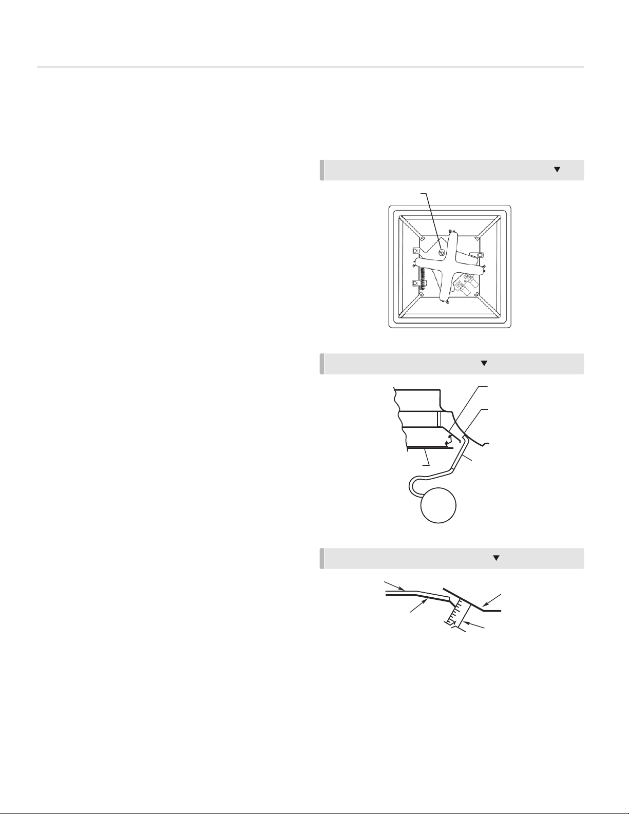
2. Open Varitherm Small Square VAV diffusers.
a. Open appearance panel.
b. Using a flat blade screwdriver or coin, turn thedamper
opening cam clockwise until the damperblades are
fully open and the blade tips toucheach other.
See Fig. 3.
c. Close appearance panel.
3. Start fans, adjust system for 100% air flow and
makesystem checks. (Measure static pressure across
filtersand coils and at sensor for static pressure controller.
Measure supply, return and branch duct air flow.)
4. Place a direct reading diffuser balancing hood over theface
of each Varitherm Small Square VAV diffuser and adjust
damperat duct takeoff to obtain maximum design air
volume.If a velocity meter is used, measure discharge
velocityat the housing (See Fig. 3). Multiply the velocity in
fpmtimes Akof .12 ft2to get air flow in cfm.
5. Return Varitherm Small Square VAV diffusers to operating
condition.
a. Open appearance panel.
b. Turn damper opening cam to allow damper blades
to close.
c. Close appearance panel.
Balancing (VKD-D)
1. The damper blade opening is factory set at ¾inch/19mm
(See Fig. 4). Readjust where necessary byturning the
damper opening cam (See Fig. 2).
2. Place a direct reading diffuser balancing hood over theface
of each VKD-D diffuser and adjust damper at ducttakeoff
to obtain design air volume. If a velocity meteris used,
measure discharge velocity at the housing (See Fig. 3).
Multiply the velocity in fpm times Akof .12 ft2toget air flow
in cfm.
SYSTEM BALANCING (VKD-HC, VKD-C)
FIG. 2 TURN DAMPER OPENING CAM TO OPEN FOR BALANCING
FIG. 3 MEASURING DISCHARGE VELOCITY
FIG. 4 MEASURING DAMPER BLADE OPENING
To remove the appearance panel:
1. Open appearance panel as described above.
2. Rotate the appearance panel away from the latch clip
bracket to force the hinge hooks open on the panel.
3. Slightly lift the panel to remove from the hinges.
To reattach the appearance panel:
1. Hang the appearance panel on the hinges.
2. Press the hinge hooks against the panel to close
around the hinge brackets.
3. Close panel as described above.
SYSTEM BALANCING (TK-HC, TK-C)
VAV systems are balanced for design air volume at
maximum air flow and systems using Therma-Fuser VAV
diffusers are no exception. When all the Therma-Fuser
diffusers are set for maximum air flow by fully opening
them, the system is really a constant air volume system
and is balanced as a constant volume system. Balancing
dampers are best located at the takeoff before the
runout to the Therma-Fuser diffuser.
1. Prepare the system for balancing. (Make necessary
checks for diversity, fan capacities, fan rotation,
miminum outside air requirements, duct leaks and
static pressure controller design settings. Set outside
air control damper for minimum air and return air
control damper for maximum air.)
2. Open Therma-Fuser diffusers.
a. Open appearance panel.
b. Using a flat blade screwdriver or coin, turn the
damper opening cam clockwise until the damper
blades are fully open and the blade tips touch
each other. See Fig. 2.
c. Close appearance panel.
Fig 2. Turn damper opening cam to open for balancing
Damper Opening Cam
3. Start fans, adjust system for 100% air flow and make
system checks. (Measure static pressure across filters
and coils and at sensor for static pressure controller.
Measure supply, return and branch duct air flow.)
4. Place a direct reading diffuser balancing hood over the
face of each Therma-Fuser diffuser and adjust damper
at duct takeoff to obtain maximum design air volume.
If a velocity meter is used, measure discharge velocity
at the housing (See Fig. 3). Multiply the velocity in fpm
times Akof .12 ft2to get air flow in cfm.
5. Return Therma-Fuser diffusers to operating condition.
a. Open appearance panel.
b. Turn damper opening cam to allow damper blades to close.
c. Close appearance panel.
Fig 3. Measuring Discharge Velocity
Diffusion
Damper
Housing
Probe
Appearance
Panel
Gauge
1250 to
2300 fpm
Figure 7 @ 200%
Figure 3 @200%
BALANCING (TK-D)
1. The damper blade opening is factory set at 3/4
inch/19mm (See Fig. 4). Readjust where necessary by
turning the damper opening cam (See Fig. 2).
2. Place a direct reading diffuser balancing hood over the
face of each TK-D diffuser and adjust damper at duct
takeoff to obtain design air volume. If a velocity meter
is used, measure discharge velocity at the housing (See
Fig. 3). Multiply the velocity in fpm times Akof .12 ft2to
get air flow in cfm.
Foam
Housing
Blade
Small Steel Rule
Fig 4. Measuring damper blade opening
Fig 5. Percent Minimum Flow vs. Blade Opening
ADJUSTING MINIMUM FLOW (TK-HC, TK-C)
Minimum flow is adjusted by turning the damper opening
cam until the damper blades are open the correct amount.
Determine the correct blade opening for the required percent
minimum flow from the graph in Fig. 5. Measure the blade
opening as shown in Fig. 3 and adjust the damper opening cam.
PERCENT of AIR FLOW CAPACITY vs. BLADE OPENING
PERCENT AIR FLOW CAPACITY
100
80
60
40
20
0
0 .10 .20 .30 .40 .50 .60 .70 .80
(0) (2.5) (5.1) (7.6) (10.2) (12.7) (15.2) (17.8) (20.3)
BLADE OPENING — INCHES
(MM)
Page 2 of 6