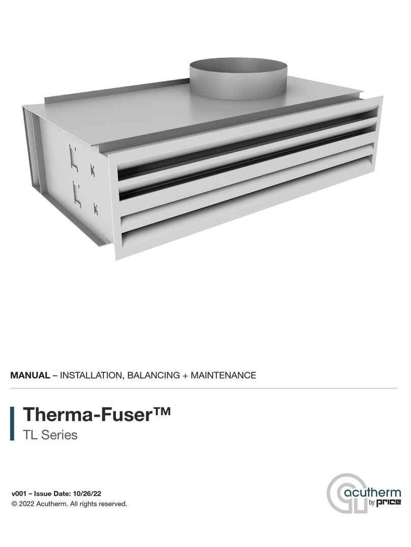
Price FCHC User manual

MANUAL – INSTALLATION
Horizontal Low-Profile Fan Coils
FCHC, FCHP, FCHE
v000 –Issue Date: 12/02/22
© 2022 Price Industries Limited. All rights reserved.

HORIZONTAL LOW-PROFILE FAN COILS
TABLE OF CONTENTS
Product Overview
Safety Precautions ........................................................ 1
Caution to Contractors.................................................. 1
Receiving Inspection ..................................................... 1
Installation & Mounting Instructions
Installation ..................................................................... 2
Concealed Horizontal Fan Coils..................................... 3
FCHP Filter Replacement .............................................. 4
Start up and Operation.................................................. 5
Maintenance
Troubleshooting Guide .................................................. 6
Fan and Motor .............................................................. 7
FCHP Filters.................................................................. 8
Replacement Parts........................................................ 9
Installation Checklist.................................................... 13

1
priceindustries.com |HORIZONTAL LOW-PROFILE FAN COILS - Manual
HORIZONTAL LOW-PROFILE FAN COILS
PRODUCT OVERVIEW
Safety Precautions
A. Installation work and electrical
wiring must be done by qualified
person(s) in accordance with all
applicable codes and standards,
including fire-rated construction.
B. When cutting or drilling into wall or
ceiling, do not damage electrical
wiring and other hidden utilities.
C. Use this unit only in the manner
intended by the manufacturer. If you
have any questions, contact the
manufacturer:
In the United States
2975 Shawnee Ridge Court
Suwanee, Georgia USA 30024
Ph: 770.623.8050
Fax: 770.623.6404
In Canada or International Export
Sales Office
638 Raleigh Street
Winnipeg, Manitoba
Canada R2K 3Z9
Ph: 204.669.4220
Fax: 204.663.2715
D. Before servicing or cleaning unit,
switch power off at service panel
and lock service panel to prevent
power from being switched on
accidentally.
E. Protect flammable materials nearby
when brazing, Use flame and heat
protection barriers where needed.
Always have a fire extinguisher
ready.
F. The manufacturer assumes no
responsibility for personal injury or
property damage resulting from
improper handling, installation,
service or operation of the product.
Caution to Contractors
1. Fan coil units are not intended for use as temporary heat or ventilation sources
during building construction. The fan coil units are not designed nor equipped
to operate in a dusty construction environment. Recirculating fan wheels can
become coated in construction dust, resulting in an unbalanced wheel, which
may contribute to reduced motor life. Inlet air filters, if supplied, provide little
protection as they would quickly become plugged with construction dust.
2. Price recommends a minimum of three (3) duct diameters of straight inlet duct,
the same size as the inlet, between the unit inlet and any transition, take-offs or
fittings.
3. Price recommends sufficient clearance for access panel removal. Local code and
the National Electrical Code clearance requirements take precedence and are the
responsibility of the installing contractor.
NOTE: Price cannot warrant against any damage or poor performance due to
operating outside of the conditions outlined above.
Receiving Inspection
All Price fan coil units are inspected before shipment. After unpacking the assembly,
check it for damage. If any damage to the products is found, report it immediately to
the delivery carrier. Caution is required when unpacking the fan powered units with
electric coils as not to damage the elements.
Ensure that all packing material is removed from the inside of the unit,
especially around the blower wheel and coil section.
WARNING: Do not adjust the control components.

2HORIZONTAL LOW-PROFILE FAN COILS - Manual |priceindustries.com
HORIZONTAL LOW-PROFILE FAN COILS
INSTALLATION & MOUNTING INSTRUCTIONS
Installation
Price fan coils are designed to be durable and manufactured for sturdy construction. The units must still be handled with great
care and no force or pressure applied to the coil or piping. When handled, the unit should be carried in an upright position holding
onto the mounting points. The fan coils are not suitable for outdoor installations. The units should never be stored or installed
where it may be subjected to a hostile environment such as rain, snow, or extreme temperatures. Care must be taken during and
after installation to prevent foreign material such as paint, drywall mud or dust from entering the drain pan or the motor or blower
wheels. Failure to do so may have serious effects on the unit performance and may cause premature failure if foreign material
is allowed to be deposited into the motor or blower. Some job conditions may require the unit to be covered temporarily until
installation.
WARNING: Do not tamper with control components.
OPTIONAL HANGER BRACKETS
Engineering Request No:
(mm/dd/
yyyy)
Initials
Completion dateFactory order no OperatorSch datePart qty
Sheet
of
Revision
Description
Drawing no.DateStatus
Drawn by Scale
Comment/TagIssued date Blank qty
FCH HANGER BRACKET
IMAGE FOR IOM
11
CNC/Tool No.
Solid Edge
Description:
Part No:
Description:
Part No:
Part No:
Material
Description:
Winnipeg
Atlanta
Casa
Grande
Rev Description ECN Date (y/m/d) By
Blank Size:
Print Date: 9/12/2017 - hb image for iom.dft
Network File Location: C:\Users\JeremyW\Desktop\hb image for iom.dft
1 1/4"
(38)
3 3/16"
(81)
1"
(25)
9/16" DIA.
(14)

3
priceindustries.com |HORIZONTAL LOW-PROFILE FAN COILS - Manual
HORIZONTAL LOW-PROFILE FAN COILS
INSTALLATION & MOUNTING INSTRUCTIONS
Concealed Horizontal Fan Coils
Mounting the Unit
1. Use trapeze hanger or optional factory supplied hanger
brackets as illustrated. Hanging rods should be securely
attached to joists or to mounting anchors which are
properly secured to slab construction with lugs or poured
in place anchors.
2. Price Fan Coil Units are designed to be mounted in the
direction indicated by the Control Assembly Label found
on the protective shroud.
3. Do not block the bottom access panel, maintain clearance
for blower service.
4. Do not install tight to slab, avoid contact with other
obstacles such as rigid conduit and sprinkler piping. This
can cause excessive vibration and noise transmission.
5. Install the unit in a location that allows free access to the
unit as well as all control components.
6. Ensure main power to the terminal has been disconnected
prior to performing any electrical work or inspection of the
circuitry.
WARNING: Do not tamper with control components.
Cooling/Heating Pipe Connections
The valve packages are easily damaged when introduced to
excessive amounts of heat. Great caution must be made when
the connections are made with “sweat” or solder joints. The
valve must be in the open position during all soldering and
brazing operations. Heat should be dissipated with a wet cloth
wrapped around the valve body.
Electrical Connection
CAUTION: Disconnect all incoming power before any electrical
installation or service is performed on the unit(s).
1. All field wiring is to be in accordance with the National
Electrical Code ANSI/NFPA No. 70 or the Canadian
Electrical Code, Part 1, CSA Standard C 22.1. Local
codes and the National Electrical Code requirements take
precedence over manufacturer recommendations, and
adherence to these codes shall be the responsibility of the
installing contractor.
2. Refer to the product identification label on each unit for
information to determine the field wire size.
FIGURE A
FIGURE B
3. Check voltage requirements prior to power supply
connection. Refer to the electrical label located on the
electrical control box and also refer to the schematic
drawing provided on the underside of the electrical control
box cover.
4. If upon energizing the electric motor excessive noise is
apparent, shut down the unit. Determine the cause by
checking for packing materials, etc. and re-energize after
corrective action has been taken.
Auxiliary Drain Pan Mounting
Auxiliary drain pan is mounted inside the attached drain pan.
See Figure A to properly align the mounting holes and install
the screw from the inside out. Once the screws are installed
ensure drain pan is in proper position leaning down against the
attached drain pan. See Figure B for proper positioning.

4HORIZONTAL LOW-PROFILE FAN COILS - Manual |priceindustries.com
HORIZONTAL LOW-PROFILE FAN COILS
INSTALLATION & MOUNTING INSTRUCTIONS
FCHP Filter Replacement
1. To remove the filter, open the filter fastener on the bottom of the plenum (Figure 1).
2. Slide our filter (Figure 2).
3. Slide in the new filter and close the filter fastener.
FIGURE 1 FIGURE 2
SLIDE OUT

5
priceindustries.com |HORIZONTAL LOW-PROFILE FAN COILS - Manual
HORIZONTAL LOW-PROFILE FAN COILS
INSTALLATION & MOUNTING INSTRUCTIONS
Start up and Operation
General
Before beginning start up operation, familiarize yourself with
the unit, options, accessories and controls so you understand
proper system operation. All personnel should have a good
working knowledge of general start-up procedures and have
the appropriate start-up and balancing guides available for
consultation.
NOTE: Water coils are not to be flipped in the field. This will
cause loss of performance due to improper piping and
condensate issues due to inadequate drainage.
Cooling/Heating Coils
Prior to the water system start-up and balancing, the chilled/hot
water systems should be flushed to clean out dirt and debris,
which may have collected in the piping during construction.
During this procedure, all unit service valves must be in the
closed position. This prevents foreign matter from entering
the unit and clogging the valves and metering devices. Filters
should be installed in the piping mains to prevent this material
from entering the units during normal operation. During system
filling, air venting from the unit is accomplished by the use of
the standard manual air vent fitting installed on the coil. Manual
air vent fitting: the screw should be turned counterclockwise
no more than 1-1/2 turns to operate the air vent.
CAUTION: The air vent provided on the unit is not intended to
replace the main system air vents and may not release air trapped
in other parts of the system. Inspect the entire system for potential
air traps and vent those areas as required, independently. In
addition, some systems may require repeated venting over a
period of time to properly eliminate air from the system.
Water System Balancing
A complete knowledge of the hydronic system, its
components, and controls is essential to proper water system
balancing and this procedure should not be attempted by
unqualified personnel. The system must be complete and
all components must be in operating condition BEFORE
beginning water system balancing operations. Each hydronic
system has different operating characteristics depending on
the devices and controls in the system. The actual balancing
technique may vary from one system to another.
After the proper system operation is established, the appropriate
system operating conditions such as various water temperatures
and flow rates should be recorded in a convenient place for
future reference. Before and during water system balancing,
conditions may exist which can result in noticeable water noise
or undesired valve operation due to incorrect system pressures.
After the entire system is balanced, these conditions will not
exist on properly designed systems.
Air System Balancing
All ductwork must be complete and connected, and all grilles,
filters, access doors and panels must be properly installed
to establish actual system operating conditions BEFORE
beginning air balancing operations. Each individual unit and
attached ductwork is a unique system with its own operating
characteristics. For this reason, air balancing is normally done
by balance specialists who are familiar with all procedures
required to properly establish air distribution and fan system
operating conditions.
These procedures should not be attempted by unqualified personnel.
After the proper system operation is established, the actual
unit air delivery and the actual fan motor amperage draw for
each unit should be recorded in a convenient place for future
reference such as the inspection, installation, & start-up check
sheet, a copy of which is provided on the back of this manual.
Contact the sales representative or the factory for additional
copies of this sheet.
The manufacturer assumes no responsibility for undesirable
system operation due to improper design, equipment or
component selection, and/or installation of ductwork, grilles,
and other field supplied components.

6HORIZONTAL LOW-PROFILE FAN COILS - Manual |priceindustries.com
HORIZONTAL LOW-PROFILE FAN COILS
MAINTENANCE
Troubleshooting Guide
General
1. Confirm fan coil size and rating with blueprint and schedule (check Control Assembly label on terminal unit).
2. Visually check electrical connections with the Control Wiring diagram(s) located inside the electrical enclosure or in the applicable
controls brochure.
3. Verify that the supply voltage is the same as specified on the control diagram(s) or Voltage Information label.
Noise
1. Foreign material in fan.
2. Fan or duct size selection too small for application causing high air velocity.
3. Vibrating duct work.
4. Unbalanced fan wheel causing it to hit the housing.
Fan Does Not
Operate
1. Check the unit wiring against the provided Control and Wiring diagrams. See inside cover of the electrical enclosure for diagrams.
2. Verify that the disconnect switch or breaker is not opened.
3. Check for proper control signal from thermostat. See thermostat for full heating and monitor output.
4. Fan wheel may be touching the housing.
Air Volume not
as Specified
1. Check filter for excessive dust build-up.
2. Check fan for particle blockage.
3. Check coils for particle blockage.
4. Measure downstream static pressure; compare to fan curve.
5. Verify that the supply voltage is the same as specified on the wiring diagram. See wiring diagram pasted on the inside of the
electrical enclosure or in the applicable controls brochure.
6. Insulating duct liner loose.

7
priceindustries.com |HORIZONTAL LOW-PROFILE FAN COILS - Manual
HORIZONTAL LOW-PROFILE FAN COILS
MAINTENANCE
Fan and Motor
1. Disconnect all incoming power before servicing the unit.
2. Price fan powered fan coil units are supplied with
permanently lubricated motors.
3. The blower and motor should be inspected annually for
accumulation of dust and dirt. Clean as necessary.
4. To access blower and motor for servicing, remove
the bottom access panel or alternate access panels if
equipped.
CAUTION: Motor may be very hot. Ensure motor has cooled
before service.
5. Motors are provided with thermal overload protection.
If the motor overheats and trips the thermal overload, it
will automatically reset after cooling down to a proper
operating temperature.
6. If field amperage draw readings of the fan motor are
required, measurements should be taken with a true RMS
meter. Non-true RMS meters will not provide accurate
reading due to alteration of the sine wave by the fan speed
control. Refer to Page 7 for motor voltage equations.
Coils
1. Disconnect all incoming power before servicing unit.
2. To access coils for servicing, remove the coil access door
(optional), or remove blower and motor assemblies.
3. The coil should be inspected periodically for accumulation
of dust and dirt. Clean as necessary. Cleaning can be
done by brushing the coils in the direction of the fins.
Compressed air can also be used to blow out dust
particles in the coil. Vacuum all dust particles so they
cannot damage the blower and motor.
Filter(s)
1. Filters, if supplied, should be replaced or removed after
system start-up.
2. If filters are used beyond system start-up they should be
changed regularly to avoid excessive restriction of air flow.
The time interval between each replacement should be
established based on regular inspection of the filter and
should be recorded in the log for each unit.
3. Refer to the “Replacement Parts” section of this manual
for list of replacement filter media.
4. If the replacement filters are not purchased from the
factory, the filters used should be the same type and size
as that furnished from or recommended by the factory.
Consult the factory for applications using filter types other
than the factory standard or optional product.
Electronically Commutated Motor (ECM) Information
Do not switch 120/208/240/277 VAC power to turn ECM
motor on and off. Instead control the 24VAC signal or BAS
signal to turn the ECM motor on and off. The ECM motor
has large capacitors that charge quickly on mains power up.
Switching on several motors frequently could reduce building
power quality and is not recommended.
Standard ECM Speed Controller
The Price standard speed controller allows manual adjustment
of the fan flow using the adjustment dial on the control board
and a voltmeter. Remote control of the fan speed is also
possible with the BAS input. The following chart describes the
controller response to a 0-10 VDC input.
Input Voltage Mode of Operation
0-1 VDC Manual Control
1-2 VDC Fan Off
2-10 VDC Remote Control 0 - 100%
Note: Refer to “Fan Curves” performance data documents for fan curves.
CONTROL ASSEMBLY LABEL
ECM CABLE CONNECTION
NOTE: Cable must be installed in the configuration or the unit
will not function as expected.

8HORIZONTAL LOW-PROFILE FAN COILS - Manual |priceindustries.com
HORIZONTAL LOW-PROFILE FAN COILS
MAINTENANCE
FCHP Filters
The type of throwaway filter most commonly used on fan coil units should be replaced on a regular basis. The time interval
between each replacement should be established based on regular inspection of the filter and should be recorded in the log
for each unit. Refer to the chart for recommended filter size for each product type and size. If the replacement filters are not
purchased from the factory, the filters used should be the same type and size as that furnished from or recommended by the
factory. Pleated media or extended surface filters should not be used since the high air pressure drops encountered with these
types of filters is not compatible with the type of fan coil unit covered in this manual. Consult the factory for applications using filter
types other than the factory standard or optional product.
Unit Size Filter Face Area Nominal Filter Sizes
Rear Return Nominal Filter Sizes
Bottom Return
02 1.14 10 1/4 x 16 x 2 10 1/4 x 16 x 1
03 1.42 10 1/4 x 20 x 2 10 1/4 x 20 x 1
04 1.85 10 1/4 x 26 x 2 10 1/4 x 26 x 1
06 2.28 (2) 10 1/4 x 16 x 2 (2) 10 1/4 x 16 x 1
08 2.85 (2) 10 1/4 x 20 x 2 (2) 10 1/4 x 20 x 1
10 3.70 (2) 10 1/4 x 26 x 2 (2) 10 1/4 x 26 x 1
12 4.27 (3) 10 1/4 x 20 x 2 (3) 10 1/4 x 20 x 1

9
priceindustries.com |HORIZONTAL LOW-PROFILE FAN COILS - Manual
HORIZONTAL LOW-PROFILE FAN COILS
MAINTENANCE
Replacement Parts
Component Part# Description
Fan Motors (ECM)
NOTE: Contact factory to
ensure motors are pro-
grammed with Modulating
or 3-Speed Motor Program.
019598-001 115-240 V - 1/4 HP - Single Shaft (FCH 02, 03, 10)
019598-002 277 V - 1/4 HP - Single Shaft (FCH 02, 03, 10)
019598-003 115-240 V - 1/4 HP - Dual Shaft (FCH 04, 06, 08, 10, 12)
019598-004 277 V - 1/4 HP - Dual Shaft (FCH 04, 06, 08, 10, 12)
ECM Wiring Harnesses 019186-017 ECM Cable, 6 ft. (FCH 02, 03, 04, 10)
019186-018 ECM Cable, 2 ft. (FCH 06, 08, 10, 12
ECM Speed Controller 232953-100 ECM Speed Controller
Disconnect Switch 019903-001 115 V / 277 V Single Pole
019903-003 208 V / 240 V Double Pole
Blowers 100152-001 Left Hand Blower (FCH 02, 03, 04, 06, 08, 10, 12)
100152-002 Right Hand Blower (FCH 04, 06, 08, 10, 12)
Water Coils
2 Row
Chilled
Water
Right
Hand
508775-021 FCH 02, 1 Circuit, Right Hand
508775-031 FCH 03, 1 Circuit, Right Hand
508775-041 FCH 04, 1 Circuit, Right Hand
508775-061 FCH 06, 1 Circuit, Right Hand
508775-081 FCH 08, 1 Circuit, Right Hand
508775-082 FCH 08, 2 Circuit, Right Hand
508775-101 FCH 10, 1 Circuit, Right Hand
508775-102 FCH 10, 2 Circuit, Right Hand
508775-122 FCH 12, 2 Circuit, Right Hand
2 Row
Chilled
Water
Left Hand
508779-021 FCH 02, 1 Circuit, Left Hand
508779-031 FCH 03, 1 Circuit, Left Hand
508779-041 FCH 04, 1 Circuit, Left Hand
508779-061 FCH 06, 1 Circuit, Left Hand
508779-081 FCH 08, 1 Circuit, Left Hand
508779-082 FCH 08, 2 Circuit, Left Hand
508779-101 FCH 10, 1 Circuit, Left Hand
508779-102 FCH 10, 2 Circuit, Left Hand
508779-122 FCH 12, 2 Circuit, Left Hand
Continued on next page...

10 HORIZONTAL LOW-PROFILE FAN COILS - Manual |priceindustries.com
HORIZONTAL LOW-PROFILE FAN COILS
MAINTENANCE
Replacement Parts Continued...
Component Part# Description
Water Coils
3 Row
Chilled Water
Right Hand
508776-021 FCH 02, 1 Circuit, Right Hand
508776-031 FCH 03, 1 Circuit, Right Hand
508776-041 FCH 04, 1 Circuit, Right Hand
508776-042 FCH 04, 2 Circuit, Right Hand
508776-061 FCH 06, 1 Circuit, Right Hand
508776-062 FCH 06, 2 Circuit, Right Hand
508776-082 FCH 08, 2 Circuit, Right Hand
508776-083 FCH 08, 3 Circuit, Right Hand
508776-102 FCH 10, 2 Circuit, Right Hand
508776-103 FCH 10, 3 Circuit, Right Hand
508776-122 FCH 12, 2 Circuit, Right Hand
508776-123 FCH 12, 3 Circuit, Right Hand
3 Row
Chilled Water
Left Hand
508780-021 FCH 02, 1 Circuit, Left Hand
508780-031 FCH 03, 1 Circuit, Left Hand
508780-041 FCH 04, 1 Circuit, Left Hand
508780-042 FCH 04, 2 Circuit, Left Hand
508780-061 FCH 06, 1 Circuit, Left Hand
508780-062 FCH 06, 2 Circuit, Left Hand
508780-082 FCH 08, 2 Circuit, Left Hand
508780-083 FCH 08, 3 Circuit, Left Hand
508780-102 FCH 10, 2 Circuit, Left Hand
508780-103 FCH 10, 3 Circuit, Left Hand
508780-122 FCH 12, 2 Circuit, Left Hand
508780-123 FCH 12, 3 Circuit, Left Hand
4 Row
Chilled Water
Right Hand
508777-021 FCH 02, 1 Circuit, Right Hand
508777-031 FCH 03, 1 Circuit, Right Hand
508777-032 FCH 03, 2 Circuit, Right Hand
508777-041 FCH 04, 1 Circuit, Right Hand
508777-042 FCH 04, 2 Circuit, Right Hand
508777-062 FCH 06, 2 Circuit, Right Hand
508777-063 FCH 06, 3 Circuit, Right Hand
508777-082 FCH 08, 2 Circuit, Right Hand
508777-083 FCH 08, 3 Circuit, Right Hand
508777-102 FCH 10, 2 Circuit, Right Hand
508777-103 FCH 10, 3 Circuit, Right Hand
508777-123 FCH 12, 3 Circuit, Right Hand
508777-127 FCH 12, 7 Circuit, Right Hand
Continued on next page...

11
priceindustries.com |HORIZONTAL LOW-PROFILE FAN COILS - Manual
HORIZONTAL LOW-PROFILE FAN COILS
MAINTENANCE
Replacement Parts Continued...
Component Part# Description
Water Coils
4 Row
Chilled Water
Left Hand
508781-021 FCH 02, 1 Circuit, Left Hand
508781-022 FCH 02, 2 Circuit, Left Hand
508781-031 FCH 03, 1 Circuit, Left Hand
508781-032 FCH 03, 2 Circuit, Left Hand
508781-042 FCH 04, 2 Circuit, Left Hand
508781-043 FCH 04, 3 Circuit, Left Hand
508781-062 FCH 06, 2 Circuit, Left Hand
508781-063 FCH 06, 3 Circuit, Left Hand
508781-082 FCH 08, 2 Circuit, Left Hand
508781-083 FCH 08, 3 Circuit, Left Hand
508781-103 FCH 10, 3 Circuit, Left Hand
508781-105 FCH 10, 5 Circuit, Left Hand
508781-123 FCH 12, 3 Circuit, Left Hand
508781-125 FCH 12, 5 Circuit, Left Hand
5 Row
Chilled Water
Right Hand
508778-021 FCH 02, 1 Circuit, Right Hand
508778-022 FCH 02, 2 Circuit, Right Hand
508778-031 FCH 03, 1 Circuit, Right Hand
508778-032 FCH 03, 2 Circuit, Right Hand
508778-042 FCH 04, 2 Circuit, Right Hand
508778-043 FCH 04, 3 Circuit, Right Hand
508778-062 FCH 06, 2 Circuit, Right Hand
508778-063 FCH 06, 3 Circuit, Right Hand
508778-082 FCH 08, 2 Circuit, Right Hand
508778-083 FCH 08, 3 Circuit, Right Hand
508778-103 FCH 10, 3 Circuit, Right Hand
508778-105 FCH 10, 5 Circuit, Right Hand
508778-123 FCH 12, 3 Circuit, Right Hand
508778-125 FCH 12, 5 Circuit, Right Hand
5 Row
Chilled Water
Left Hand
508782-021 FCH 02, 1 Circuit, Left Hand
508782-022 FCH 02, 2 Circuit, Left Hand
508782-031 FCH 03, 1 Circuit, Left Hand
508782-032 FCH 03, 2 Circuit, Left Hand
508782-042 FCH 04, 2 Circuit, Left Hand
508782-043 FCH 04, 3 Circuit, Left Hand
508782-062 FCH 06, 2 Circuit, Left Hand
508782-063 FCH 06, 3 Circuit, Left Hand
508782-082 FCH 08, 2 Circuit, Left Hand
508782-083 FCH 08, 3 Circuit, Left Hand
508782-103 FCH 10, 3 Circuit, Left Hand
508782-105 FCH 10, 5 Circuit, Left Hand
508782-123 FCH 12, 3 Circuit, Left Hand
508782-125 FCH 12, 5 Circuit, Left Hand
Continued on next page...

12 HORIZONTAL LOW-PROFILE FAN COILS - Manual |priceindustries.com
HORIZONTAL LOW-PROFILE FAN COILS
MAINTENANCE
Replacement Parts Continued...
Component Part# Description
Water Coils
1 Row
Hot Water
Right Hand
508783-021 FCH 02, 1 Circuit, Right Hand
508783-031 FCH 03, 1 Circuit, Right Hand
508783-041 FCH 04, 1 Circuit, Right Hand
508783-061 FCH 06, 1 Circuit, Right Hand
508783-081 FCH 08, 1 Circuit, Right Hand
508783-101 FCH 10, 1 Circuit, Right Hand
508783-121 FCH 12, 1 Circuit, Right Hand
1 Row
Hot Water
Left Hand
508785-021 FCH 02, 1 Circuit, Left Hand
508785-031 FCH 03, 1 Circuit, Left Hand
508785-041 FCH 04, 1 Circuit, Left Hand
508785-061 FCH 06, 1 Circuit, Left Hand
508785-081 FCH 08, 1 Circuit, Left Hand
508785-101 FCH 10, 1 Circuit, Left Hand
508785-121 FCH 12, 1 Circuit, Left Hand
2 Row
Hot Water
Right Hand
508784-021 FCH 02, 1 Circuit, Right Hand
508784-031 FCH 03, 1 Circuit, Right Hand
508784-042 FCH 04, 2 Circuit, Right Hand
508784-062 FCH 06, 2 Circuit, Right Hand
508784-082 FCH 08, 2 Circuit, Right Hand
508784-102 FCH 10, 2 Circuit, Right Hand
508784-122 FCH 12, 2 Circuit, Right Hand
2 Row
Hot Water
Left Hand
508786-021 FCH 02, 1 Circuit, Left Hand
508786-031 FCH 03, 1 Circuit, Left Hand
508786-042 FCH 04, 2 Circuit, Left Hand
508786-062 FCH 06, 2 Circuit, Left Hand
508786-082 FCH 08, 2 Circuit, Left Hand
508786-102 FCH 10, 2 Circuit, Left Hand
508786-122 FCH 12, 2 Circuit, Left Hand
Filters
MERV 8
274831-101 FILTER, 1" (FCHE & FCHP Bottom Return 02, 06)
274831-102 FILTER, 1" (FCHE & FCHP Bottom Return 03, 08, 12)
274831-103 FILTER, 1" (FCHE & FCHP Bottom Return 04, 10)
274833-101 FILTER, 2" (FCHP Rear Return 02, 06)
274833-102 FILTER, 2" (FCHP Rear Return 03, 08, 12)
274833-103 FILTER, 2" (FCHP Rear Return 04, 10)
MERV 13
274832-101 FILTER, 1" (FCHE & FCHP Bottom Return 02, 06)
274832-102 FILTER, 1" (FCHE & FCHP Bottom Return 03, 08, 12)
274832-103 FILTER, 1" (FCHE & FCHP Bottom Return 04, 10)
274834-101 FILTER, 2" (FCHP Rear Return 02, 06)
274834-102 FILTER, 2" (FCHP Rear Return 03, 08, 12)
274834-103 FILTER, 2" (FCHP Rear Return 04, 10)

13
priceindustries.com |HORIZONTAL LOW-PROFILE FAN COILS - Manual
HORIZONTAL LOW-PROFILE FAN COILS
MAINTENANCE
Installation Checklist
Receiving & Inspection
Unit received undamaged
All parts accounted for
Unit arrangement/hand correct
Handing and Installation
Unit mounted level and plumb
Correct electrical service
Proper access available
for unit and components
Correct overcurrent
protection provided
Rubber grommet isolators used
Correct service switch/
disconnect provided
Correct chilled water line to the unit
Correct hot water line to the unit
Code compliance for all components
Shipping screws and
hardware removed
Unit protected from dirt
and foreign matter
Cooling/Heating Connections
Unit mounted level and plumb
Correct electrical service
Proper access available
for unit and components
Correct overcurrent
protection provided
Rubber grommet isolators used
Correct service switch/
disconnect provided
Correct chilled water line to the unit
Correct hot water line to the unit
Code compliance for all components
Shipping screws and
hardware removed
Ductwork Connections
Correct supply and return
grille type and size
Flexible duct connections to unit
Insulate ductwork as required
Control outside air to
protect from heat/cold
Electrical Connections
Refer to unit wiring diagram
Wiring in code compliance
Connect power service
Unit Startup
Unit mounted level and plumb
Correct electrical service
Proper access available
for unit and components
Correct overcurrent
protection provided
Rubber grommet isolators used
Correct service switch/
disconnect provided
Correct chilled water line to the unit
Correct hot water line to the unit
Code compliance
for all components
Shipping screws and
hardware removed

This document contains the most current product information as of this printing.
For the most up-to-date product information, please go to priceindustries.com
© 2022 Price Industries Limited. All rights reserved.
This manual suits for next models
2
Table of contents
Other Price Fan manuals

Price
Price acutherm TF Series User manual

Price
Price DFW Series User manual

Price
Price Acutherm Advantage Master User manual

Price
Price acutherm Advantage User manual

Price
Price Acutherm THERMA-FUSER SYSTEMS User manual

Price
Price FFU series Manual

Price
Price VKD Series User manual

Price
Price acutherm Therma-Fuser TL Series User manual

Price
Price Acutherm TLW-C Instructions for use

Price
Price Prodigy Safety guide