manuals.online logo
Brands
  1. Home
  2. •
  3. Brands
  4. •
  5. Prier
  6. •
  7. Plumbing Product
  8. •
  9. Prier P-754 Guide

Prier P-754 Guide

PRIER Products, Inc.
4515 E 139th St.
Grandview, MO 64030
800-362-9055
www.PRIER.com/P-754
Installation, Operation & Maintenance Instructions for the
PRIER P-754 Hot & Cold Commercial Wall Hydrant
*Please leave this sheet for the property owner*
Thank you for purchasing the PRIER P-754 Hot & Cold Commercial Wall Hydrant, the nest quality commercial
hydrant available. Your P-754 will provide you years of dependable service with little or no maintenance.
Please note: Your P-754 hydrant has drain holes under the packing nut. After shuto󰀨, the drain holes will allow water to
drain for a few moments to prevent freezing. This is normal and according to design.
Installation:
Installation procedures may vary slightly depending on the application and choice to use the P-754BX1 hydrant box. The
P-754 wall hydrant is available only in the M inlet (¾” MPT):
Operation:
Operation of the P-754 Commercial Wall Hydrant is a simple process. Water ows through the hydrant after turning the
loose key one full turn counter-clockwise to the “on” position. The hydrant will achieve maximum ow at 2 1/2 full turns.
At any time during the “on” position the temperature dial can be rotated clockwise (to the right) for cold water or counter-
clockwise (to the left) for hot water. Turn o󰀨 the hydrant by turning the loose key fully clockwise to the “o󰀨” position. The
hydrant will drain for a few moments. If the dripping persists after a few moments, tighten the key slightly until the dripping
stops. Be careful not to overtighten the hydrant.
The P-754 incorporates an integral ASSE 1052 atmospheric anti-siphon vacuum breaker that, in the rare occurrence of a
back siphon- age, opens to the atmosphere preventing contamination of the water supply.
As well as an atmospheric vacuum breaker, the P-754 incorporates a check valve in the rare case that water is forced
backwards into the valve.
*ALWAYS REMOVE HOSE DURING FREEZING TEMPERATURES*
1. Determine the location for the installation of the hydrant. Ensure there is adequate work room in the interior of the
structure for securing the hydrant to the plumbing piping.
2. For installation without a box, use the cardboard template located on the hydrant box, cut a 4” Wide x 4 1/2” Tall open-
ing through the wall in the desired position for the installation.
3. For installation with a box, use the cardboard template located on the box, cut a 6” Wide x 7 1/2” Tall opening through
the wall in the desired position for the installation.
4. Insert the hydrant into the cutout and temporarily secure to connect the water supply. If using a box, fully secure the
box to the structure (can use the optional (4) 3/8-16 lugs on the back of the box), loosely install the stainless steel
mounting plate and hydrant to the box using the (4) #10-24 screws provided.
5. If you are planning to solder the connection, be certain to keep heat away from the threaded connection as there is a
plastic check valve installed to prevent thermal migration.
6. Connect the water supply piping to the hydrant as desired. Make sure to connect the hot supply to the inlet marked
with RED. With a closed-end hose on the valve creating back pressure, test the installation for leakage.
7. After the water supply connection is made, secure the mounting plate to the structure with appropriate fasteners, or if
using a box secure the (4) screws to hold the hydrant to the box.
Maintenance:
The P-754 Heavy Commercial Wall Hydrant leaves the factory fully air tested and operational. It is treated with an FDA
approved lubrication. The hydrant requires no scheduled maintenance to provide long life. If the stem is removed, the
bypass O-Ring needs to be replaced and lubricated with an FDA approved lubricant to avoid tearing.

4515 East 139th Street
Grandview, MO 64030
(800) 362-9055
Fax (800) 362-1463
www.PRIER.com
ID Part No. Description ID Part No. Description
1 See Below Stem Assembly, Contains: 5, 14 310-6009 1” Hose Piece for C-636 (NP Brass)
P-231-0604 Stem for 4” C-634 Hydrant, 4 11/16” OAL 5 336-0001 O-Ring Worm Sleeve
P-231-0606 Stem for 6 “ C-634 Hydrant, 6 11/16” OAL 6 336-6001 O-Ring Worm Drive
P-231-0608 Stem for 8” C-634 Hydrant, 8 11/16” OAL 7 337-6001 Check Spider-Vacuum Breaker
P-231-0610 Stem for 10” C-634 Hydrant, 10 11/16” OAL 8 346-6001 Diaphragm-Vacuum Breaker
P-231-0612 Stem for 12” C-634 Hydrant, 12 11/16” OAL 10 C-108KT-808 Loose Key on Lanyard
P-231-0614 Stem for 14” C-634 Hydrant, 14 11/16” OAL 11 C-634KT-802 Stopper Kit, Includes Stopper and Pin
P-231-0616 Stem for 16” C-634 Hydrant, 16 11/16” OAL 12 324-0004 Pin Only
P-231-0618 Stem for 18” C-634 Hydrant, 18 11/16” OAL 13 C-634KT-806 Vacuum Breaker Assembly
P-231-0620 Stem for 20” C-634 Hydrant, 20 11/16” OAL 14 C-634KT-808 Worm Sleeve with O-Ring, Pin and Tool
P-231-0622 Stem for 22” C-634 Hydrant, 22 11/16” OAL 15 C-634KT-809 Worm Drive Assembly with O-Ring
P-231-0624 Stem for 24” C-634 Hydrant, 24 11/16” OAL 16 C-634WCR Wall Clamping Ring
2 300-6003 Valve Stem Cap (NP Brass) 17 399-0001 Secondary Check for ASSE 1052
3 300-6004 3/4” Hose Piece (NP Brass) C-634KT-807 C-634 Overhaul Kit, Contains: 10, 11, 12, 13, 14
Replacement Parts & Stems Rough-In Dimensions
1
2
13
7 8 3 17
10
16
14 15
65
11
Furnish and install Model P-754 Heavy Commercial Wall Hydrant manufactured by PRIER Products, Inc. Hydrant shall have automatic draining
capabilities with integral vacuum breaker/backow preventor. Hydrant shall ow 19 gallons per minute minimum at 25 PSI Di󰀨erential and be at
full ow in 2 handle rotations. Hydrant shaft shall be brass with threaded and sealed connections. Hydrant shall have 3/4” hose connection with
freezeless water ow and self-draining functions, one piece valve plunger, satin nickel nish, brass operating rod with positive triple seal shuto󰀨
mechanism. Hydrant shall be approved under ASSE 1052 standard. Operating key & wall clamping ring to be furnished with each hydrant.
Hydrant insertion length to be * inches.
Optional: Furnish and install ush-mount hydrant box for each valve. Hydrant box shall be manufactured of solid cast brass. Box may be installed
separately and hydrant be insertable and removable from front of the box. Access to the hydrant box shall be provided by the same operating
key as the valve. *4” to 24” in 2” increments.
Specs
12
*When assembling the vacuum breaker, ensure the
dome is facing out on the check spider and the step
is facing out on the silicone washer.
5”
5.5”

Other Prier Plumbing Product manuals

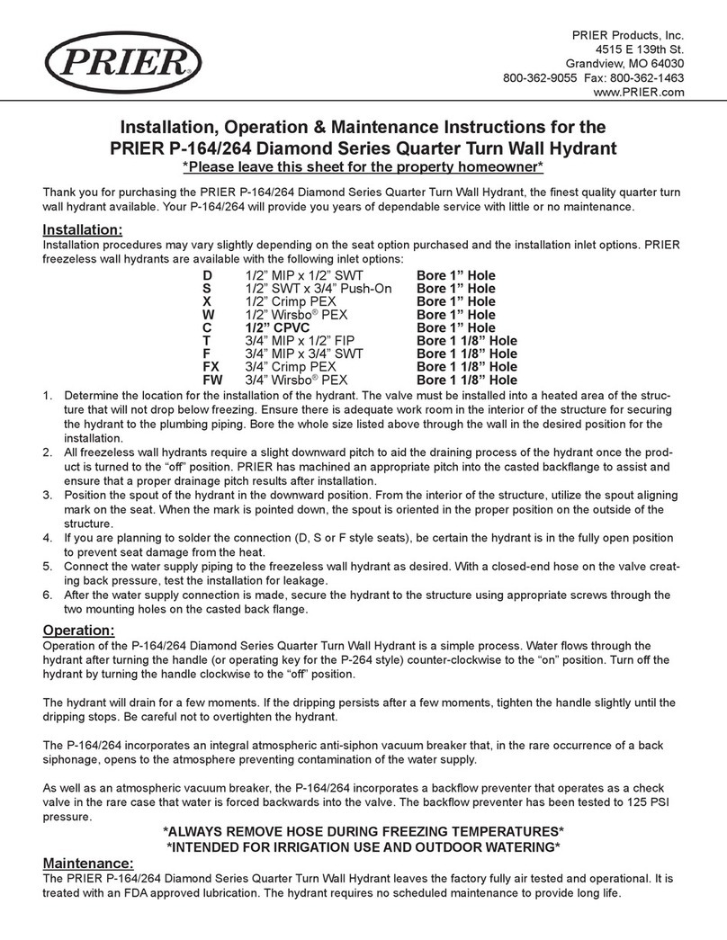
Prier P-114 Series Guide

Prier

Prier P-114 Series Guide

Prier P-118 User manual

Prier

Prier P-118 User manual

Prier P-650 Guide

Prier

Prier P-650 Guide

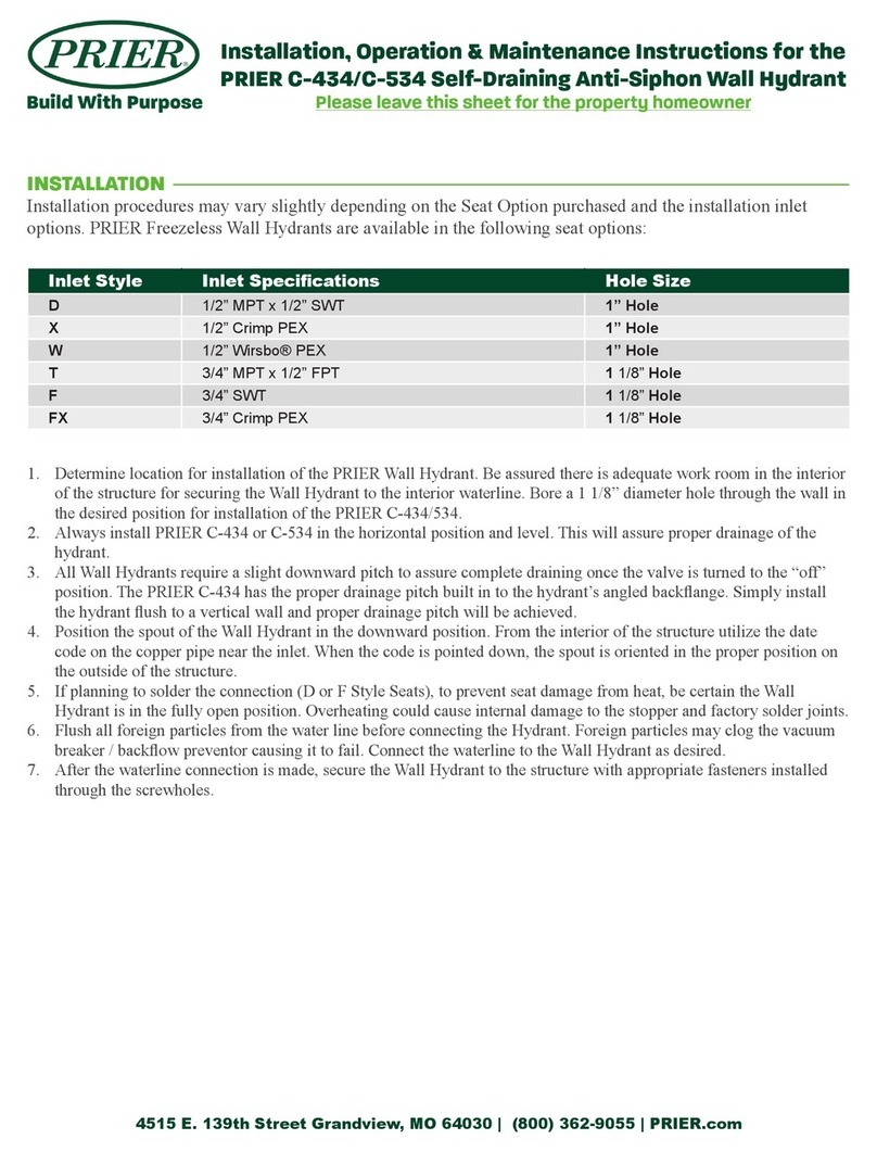
Prier P-164/264 Guide

Prier

Prier P-164/264 Guide

Prier C-434 Guide

Prier

Prier C-434 Guide

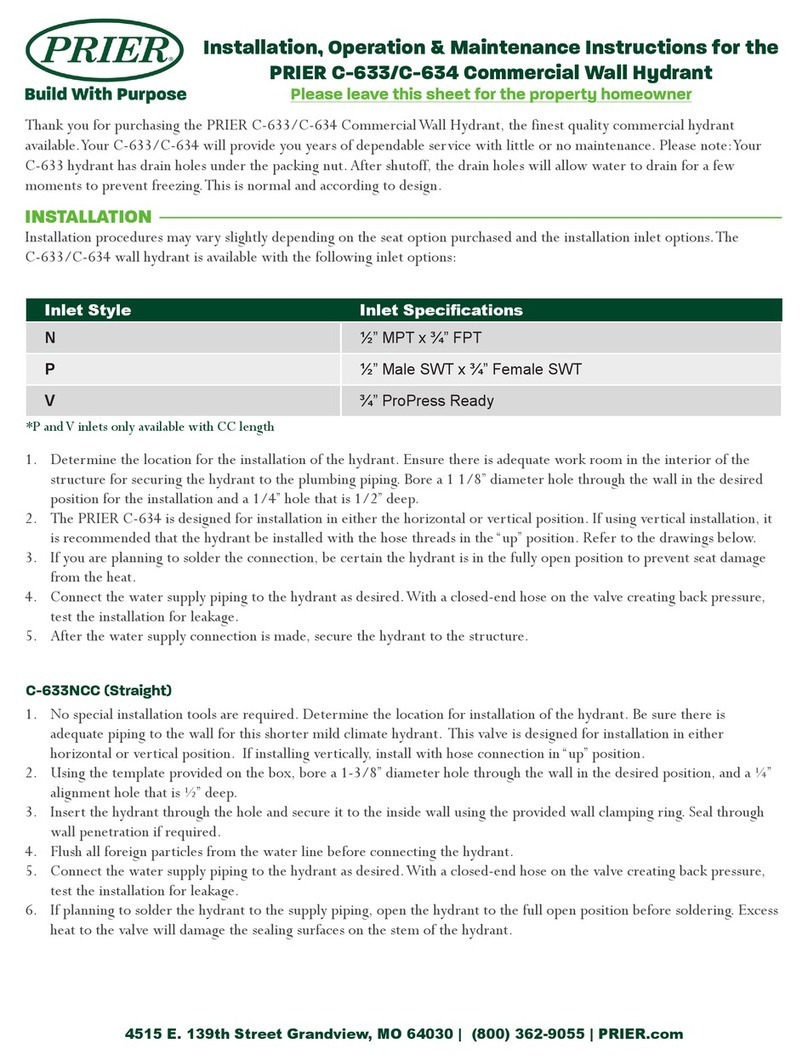
Prier C-633 Guide

Prier

Prier C-633 Guide

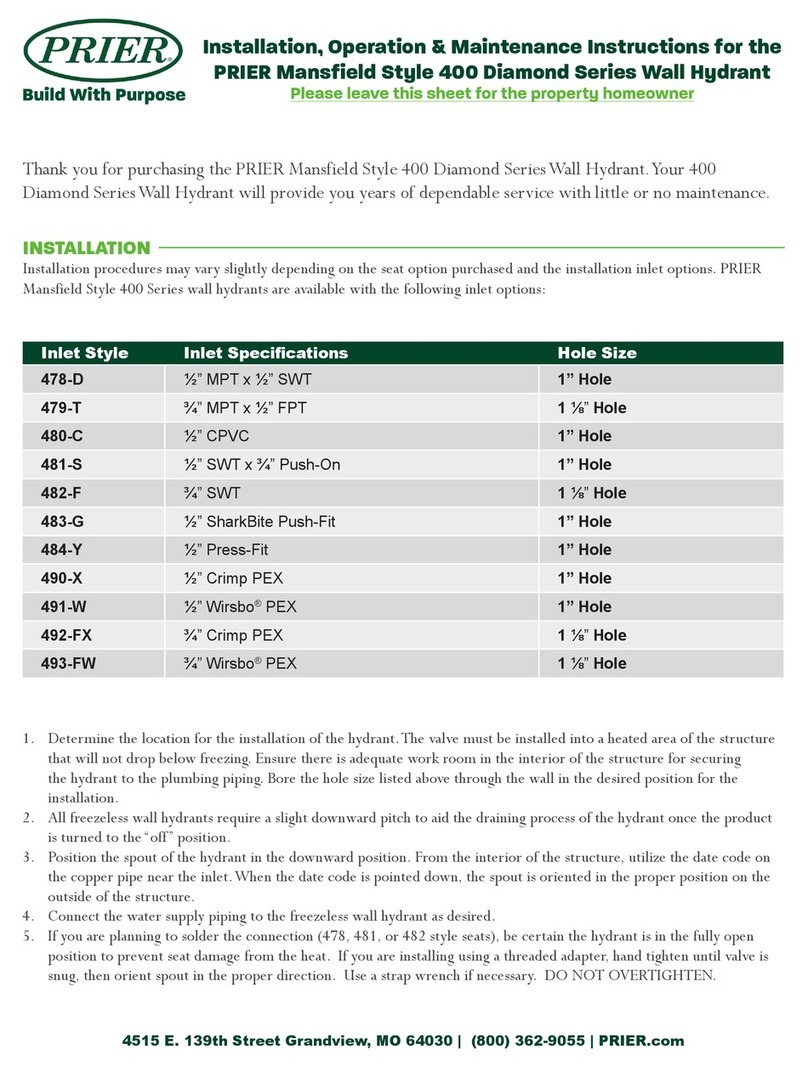
Prier 400 Diamond Series Guide

Prier

Prier 400 Diamond Series Guide

Popular Plumbing Product manuals by other brands

Fontana Showers FS145112 installation instructions

Fontana Showers

Fontana Showers FS145112 installation instructions

Symmons Origins 9600-PLR Operation & maintenance manual

Symmons

Symmons Origins 9600-PLR Operation & maintenance manual

Premier 120125 Installation

Premier

Premier 120125 Installation

Kebo F-5121-3 manual

Kebo

Kebo F-5121-3 manual

Hans Grohe iBoxPlug 1W-D40 25021180 Instructions for use/assembly instructions

Hans Grohe

Hans Grohe iBoxPlug 1W-D40 25021180 Instructions for use/assembly instructions

Krowne SILVER Series installation manual

Krowne

Krowne SILVER Series installation manual

Acorn Safety S0706 Installation, operation and maintenance instructions

Acorn Safety

Acorn Safety S0706 Installation, operation and maintenance instructions

Lefroy Brooks X1-2040 Installation, operating,  & maintenance instructions

Lefroy Brooks

Lefroy Brooks X1-2040 Installation, operating, & maintenance instructions

flamco Flamcovent Clean Installation and operating instructions

flamco

flamco Flamcovent Clean Installation and operating instructions

Glacier bay 67099-0A01 Installation and care guide

Glacier bay

Glacier bay 67099-0A01 Installation and care guide

Brizo Siderna 85880 Series installation instructions

Brizo

Brizo Siderna 85880 Series installation instructions

Omnires Darling DA5021 Installation and Maintenance

Omnires

Omnires Darling DA5021 Installation and Maintenance

Sterling Plumbing 61040116 Specification sheet

Sterling Plumbing

Sterling Plumbing 61040116 Specification sheet

BELLOSTA ELITE 9000 Installation instruction

BELLOSTA

BELLOSTA ELITE 9000 Installation instruction

Schon 65710N-B8401 Installation and care guide

Schon

Schon 65710N-B8401 Installation and care guide

Gessi RIVIEVO 59089 manual

Gessi

Gessi RIVIEVO 59089 manual

Kohler STATEMENT K-26325T-CP installation instructions

Kohler

Kohler STATEMENT K-26325T-CP installation instructions

KOLO NEXT HKPF 80 installation manual

KOLO

KOLO NEXT HKPF 80 installation manual

manuals.online logo
manuals.online logoBrands
  • About & Mission
  • Contact us
  • Privacy Policy
  • Terms and Conditions

Copyright 2025 Manuals.Online. All Rights Reserved.