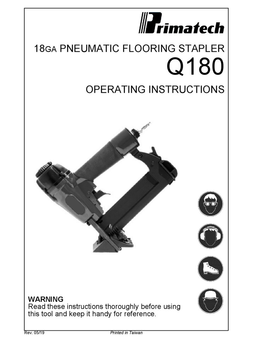
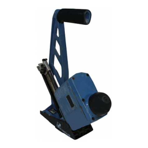
primatech P250A User manual

P250A
PNEUMATIC FLOORING TOOL
OPERATINGINSTRUCTIONS
WARNING
Read theseinstructionsthoroughlybeforeusingthistooland keep it
handyforreference.
Printed inCanada v143, 08/15

PRIMATECH PNEUMATIC TOOL P250A
The pneumaticflooring toolP250Aisaprofessionalprecision
toolspeciallydeveloped forthe installation of5/8"to 7/8"solid
hardwood flooring instandardversion, orfrom 3/4"to 33/32"
forthe GYM-version. It hasbeen designed foreasy
maintenancewheremajorcomponentscanbeaccessedwithin
secondswithout the need ofanytool.Weighting only
11 pounds(5kg),thisergonomicallydesigned toolmakesthe
installation ofhardwood floorveryeasy, allowing the operator
to set and fasten the boardsinthe standing position. It is
offered in 3 different configurations:
•standard L-type 16GA nailsinlengthsof1½"(38 mm),1¾"
(44 mm)or2"(50 mm)
•T-type 16GA nailsin length of1½"(38 mm)or2"(50 mm)
•½"crown15½GA staplesinlengthsof1½"(38 mm),1¾"
(44 mm)or2"(50 mm)
The P250Aisbuilt around the
Primpact valve engine, a
breakthrough technologyfor
pneumatictools. Primpact main
featuresare:
•short nose and compact valve design with an all-
around striking surface
•high-speed action and fewmoving parts, fora
powerfulyet soft stroke and increased precision.
•reciprocalstriking systemthat regulatesthe depth of
penetration independentlyfromthe mallet impact
•finelythreaded screw-in cartridge assembly
Forbestresult, onlyPRIMATECH fasteners shouldbe used.
Read carefullytheseinstructionsbeforeoperating thistool.It
isimportantto understand warnings/cautionsand the safety
measuresto ensure safe use ofthistool.
Additionalinformation isavailabledirectlyfromthe manufac-
turer:
1135 Jérémie-Fortin, Québec, QC
Canada, G1J1R8
Phone: 1 (800)363-1962 or1 (418)522-7744
Fax: 1 (418)522-7466
email: support@primatech.ca
web: http://support.primatech.ca
SAFETYMEASURES
Theseimportant guidelinesshouldalwaysbe followed to work
safelywith the PRIMATECH pneumatictoolmodelP250A:
•Readtheseinstructionsthoroughlybeforeusingthistooland
keep it handyforreference ifnecessary.
•Alwayskeep hands, feet orotherbodypartsawayfromthe
fastenerejection area.
•Neveraimthe toolinanydirection otherthan the working
area.
•Alwayscarryormanipulatethetoolbyitshandlewhiletheair
supplyhose isconnected.
•Neverhitthe head cap ofthe actuatorifthe plasticbaseis
not sitting perfectlyon the working surface.
•Neverleavethe toollaying downon itsside whilethe air
supplyhoseisconnected; the toolshouldalwaysbe lefton
the floor, standing on itsplasticbase.
•Do not alterorremove safety.
•Alwaysdisconnectthe airsupplyhosewhen the toolisnotin
use orwhen move to anotherworkarea.
•Neverserviceorrepairthe tool, clearobstructionsormake
adjustmentswhile the airsupplyhose isconnected.
•Onlycompressed airshouldbe used to powerthistool;do
not exceed 110 psi(7.6 bar).
•Neveruseoxygen oranyothercompressed gasasapower
source forthistool. Explosion mayoccur.
•AlwayswearOSHA-required Z-87 safetyglasseswith side
shields.
•Alwayswearproperearand foot protectionwhilethe air
supplyhose isconnected.
•Alwaysremovefasteners fromthe magazine before
servicing tool.
DO NOT REMOVE ORALTERSAFETY.DO NOT USE A
TOOL WITHADEFECTIVE SAFETY.NEVERDEPRESS THE
SAFETYCONTACT WITHYOUR HANDSWHENTOOL IS
CONNECTEDTO AIRSUPPLY.EXTREME CAUTIONIS
ADVISEDWHENUSING THISTOOL.
Eyeprotectionisrecommendedandshouldbe
wornbythe operatorand otherinworking
area. Accidentalejection offasteners orwood
debriscould cause severe eye injury.
In some environments, earprotection might
be required, asworking condition may
include exposure to high noise levelswhich
lead to hearing damage.
Wearing safetybootsand safetyhat isalso
highlyrecommended.
NOTE:Allthe personalprotection equipments
must meet nationalstandards.

CONNECTION&AIRSUPPLYSYSTEM
Toensuremaximum performanceand efficiency,and alsoa
minimumofcare, thistoolrequiresclean &dryair.The useof
a filterand a pressure regulatorisrecommended.
Thistoolneedsadetachablemalecouplerwith3/8"NPTmale
treads.The useofa3/8"(1cm)diameterairsupplyhoseis
recommended. Asmallerhoseorahoselongerthan 50'
(15 m)couldcauseapressuredrop when the toolisactivated
repeatedly.
ALWAYSUSE AFREE-FLOWCONNECTIONFORTHE
COMPRESSEDAIRSUPPLYTO PREVENT THAT THETOOL
STAYSCHARGEDAFTERDISCONNECTING THEAIR
SUPPLYHOSE.
UNLOADTOOL BEFORECONNECTING AIRTO PREVENT
ACCIDENTAL DISCHARGE.
AFTERMOVING TOOL TO ADIFFERENT WORK AREA,OR
AFTERANYMAINTENANCETO THETOOL,ALWAYS
ENSUREPROPEROPERATIONBYACTUATING TOOL
SEVERAL TIMES WITHOUT FASTENERS OVERTHE
SUBFLOORING .
Dirt, dust, and otherparticlesinthe airsupplycan cause
sluggishoperation orprematurewearofmanycomponentsof
the tool. Drain waterfromthe compressortankregularly.The
compressorstart-stop limitsshouldbe set to deliveran air
pressureofat least100 psi(7bar) at all times.Consultthe
compressormanualordealerforinstructionson howto make
thisadjustment.
At80 psi(5.5 bar) and 100 hitsperminute, thistoolconsumes
approximately4.7cu.ft(130R)ofairperminuteat70EF(21EC).
Higherairpressurewill increasethe consumption of
compressed air.
Thistoolisdesigned to be operated with acompressedair
pressureof 80 to 100 psi(5.5-7.0 bar).Airpressureof90 psi
(6.2bar)isadequateformostsituations,althoughoccasionally,
ahigherpressurecouldbe necessary.Alwaysusethe toolsat
minimumoperating pressureinorderto avoidunnecessary
highnoiselevel.In thesemoredifficultcases,thecompressed
airpressurecan be increased up to 100 psi(7.0 bar).It isvery
important not to exceed this maximumpressureto prevent
leaks, premature wearordamagesto the tool.
Checkthe compressed airsupplyhosebeforeconnecting to
ensurethat itisfree fromdirtorparticlesthat can alterthe
performanceofthe tool.Payspecialattention to anyairleaks.
Do not useacompressed airpressurehigherthan 110 psi
(7.6 bar).Higherpressurecan causeprematurewearor
damage to certaincomponents.Afterassembly,checkall the
connectionsto prevent the leaksand to havemaximum
efficiency.
TO PREVENT ACCIDENTAL DAMAGETO THEFINISHED
SURFACEOF THEINSTALLEDFLOOR,REST THETOOL
ONTO THESUBFLOORING WHENCONNECTING AIR,
LOADING TOOL ORPERFORMING ANYMAINTENANCETO
THETOOL.
LOADING THE TOOL
Thistoolcomesin one of3 different configurations:
•L-type 16ga nailsinlengthsof1½"(38 mm),1¾"(45 mm)
or2"(50 mm)
•T-type 16ga nailsinlengthsof1½"(38 mm)or2"(50 mm)
•½"crown15½ga staplesinlengthsof 1½"(38 mm),1¾"
(45 mm)or2"(50 mm)
USE ONLY THETYPE OF FASTENERSIDENTIFIEDONTHE
MAGAZINE.THEUSE OF ANYOTHERTYPE OF
FASTENERSWILL DAMAGETHETOOL.
P250AL – Loading the toolwith L-type 16ga nails:
Thistoolisfitted with the technology.Itsautomatic
magazine holds&feeds200 nails(2 strips) in an assembly
nolongerthanaconventionalone.Itsexclusivepusherlocks
into apre-armed position, allowing nailsto be fed bygravity
until it automaticallyengagesbehind. To load the tool:
•Insertone ortworowsofflooring nailsinto the backend of
the magazine.
•Pullthe pusherbackcompletelyandreleaseituntilitlocks
in position orengagesbehind the nails.
•Toremovenailsfromthe magazine, simplysqueezethe
pusherwith yourthumband indexfingerand allowitto
recoil slowly. You can then slide out remaining nails.
P250AT– Loading the toolwith T-type nails:
•InsertarowofT-type nailsinto the backend ofthe
magazine.
•Pull backon the pusheruntil it engagesbehind the nails.
•Toremovenailsfromthemagazine, simplysqueezethe
pusherwith yourthumband indexfingerand allowitto
recoil slowly. You can then slide out remaining nails.
P250AS – Loading the toolwith flooring staples:
Thistoolsisfittedwith the technology.Itsautomatic
magazine hold&feed 4stripsofflooring staplesinan
assemblyno longerthanaconventionalone. Itsexclusive
pusherlocksinto apre-armed position,allowing staplesto
be fed bygravityuntil itautomaticallyengagesbehind. To
load the tool:
•Insertup to 4stripsofflooring staplesinto the backofthe
magazine.
•Pullthepusherbackcompletelyandreleaseituntil itlocks
in position orengagesbehind the last strip.
•Toremovestaplesfromthe magazine, pull back
completelyand holdthe pusher,tiltthe toolto slide back
remaining staples.

ADJUSTING FORHARDWOODTHICKNESS
TheP250Apneumatictoolisfitted with afullyadjustable
plasticbasedesigned to prevent contactwith the top edgeof
the flooring. It isimportant to adjustthe toolto fitthe flooring
prioranyinstallation. It alsofeaturesaresting blockwhich
prevent damage to the top edge of the flooring bypositioning
the toolagainstthe tongue, preventing the gate/foot assembly
fromcontacting the board.
Step 1: adjusting the base forflooring thickness:
•UsingthesuppliedAllenwrench,loosenbutdonotremove
screws(A); two on each side ofthe tool.
•With the toolinan upside downposition, placeashort
piece offlooring against the gate/foot assembly.
•Engage theAllen wrenchinknob (B)asshown; rotate to
movethe baseup ordown. Note thatknob (B)hasa
rotation range ofonlyabout 1/2 turn. Do not applyforce
when a limit isreached.
•Adjustthe height ofthe plasticbaseto obtainasmall gap
between the gate/foot assemblyand the top side ofthe
tongueofthe sampleboard. Agap of1/32"shouldbe
adequate formost situations.
•Tighten both screws(A).
Step 2: adjusting the resting blockforthe width ofthe tongue:
•Using the Allen wrench, loosen byabout 1/2 turn do not
remove the two screws(C).
•With the shortpieceofflooring still againstthe gate/foot
assembly,adjustthe gap between the resting blockand
the tongue with screw(D).Asmall gap of1/32"shouldbe
adequate formost situations.
•Tighten both screws(C).
•Ensurethatscrew(D)isslightlytighten.Donotapplyforce
on screw(D)once screws(C)are tighten.
Aftercompleting the adjustment procedure, proceed with the
installation offewboards.Carefullycheckforthe proper
positioning ofthe fasteneronto the board. Checkagainafter
fewmorerowsto insurethat all partsaresecured inplace.
Toolmayloseadjustment overtimeifthisprocedureisnot
strictlyfollowed.
BEFORESTARTING ANINSTALLATION,FASTENDOWN
FEWBOARDSTO ASCERTAINTHAT YOUAREUSING THE
RIGHT TOOL AND FASTENER.
ADJUSTING ROLLERBASE
The P250Acan bemounted on arollerbase(standardon
P250AR &P250AG).
Step 1: adjusting the backrollers forflooring thickness:
•Using the 3/16"wrench, unfasten but do not remove
screws(A), on each side.
•Put the toolupside downand position ashortpieceof
flooring against the gate/foot assembly.
•Engage the 3/16"wrenchinknob (B)asshown; rotate to
movethe baseup ordown. Note that the rotation range is
onlyabout 1/2 turn, do not applyunnecessaryforcewhen
a limit isreached.
•Adjustthe height ofthe baseto obtainasmall gap
between the gate/foot assemblyand the top side ofthe
tongue ofthe sampleboard. Agap of1/32",about halfthe
thickness ofthe nail,shouldbe adequate formost
situations.
•Tighten both screws(A).
Step 2: adjusting the resting blockforthe width ofthe tongue:
•The front rollers are alwaysincontactwith the front edge
of the board. It isnecessaryto adjustthe resting blockto
maintainasmall gap between itand the tongue ofthe
board.
•Using the 3/16"wrench, unfasten byabout 1/2 turn do
not remove the two screws(C).
•With the shortpieceofflooring still againstthe gate/foot
assembly,adjustthe gap between the resting block and
the tongue. Asmall gap of1/32",about halfthe thickness
ofthe nail, should be adequate formost situations.
•Tighten both screws(C).

OPERATION
Unload tooland restitonto the subflooring, Connectthe hose
and cycletoolonceortwicewithout fastener.Afterloading the
tool, the toolisreadyforuse.
Useonlythe 2.5 lbs(1.1 kg)hammersupplied with the tool.
The useofothertype ofhammers mayaffectperformance.
The rubberfaceofthe hammercan be used with careto help
position the boards.
With the flooringfirmlyinplace, position the
toolonto the flooring, with the resting block
P-534 againstthe tongue. Applydownward
pressureto ensureproperseating ofthe
fastener.Strikethe head cap with the hammer
toactivatethe tool,Use onlythe RUBBERFACE
of thehammerto activatethetool. Using
thesteel end will damagethetooland void
thewarranty. Ifwood isslightlytwisted, hitting the toolwith
moreforcewill assistinpulling the boardup snugly. NEVER
strikethe head cap when the toolisnot sitting on the working
surface.
OPERATING THETOOL WHENTHESAFETYCONTACT IS
NOT FULLYDEPRESSEDWILL CAUSE PREMATUREWEAR
ORDAMAGETO THEDRIVING BLADE,PISTONAND
CYLINDER.
Beitraw,factoryfinishedorengineered,hardwoodisanatural
materialsubjectto variousfactors,suchashumidity,
subflooring,installationprocedure,typeoftools,fasteners,etc.
Installershouldalwaysensureoptimalsurfacepreparation,
complywith all manufacturers recommendationsand conduct
a pre-installation test priorto beginning anyinstallation.
BEFORESTARTING ANINSTALLATION,FASTENDOWN
FEWBOARDSTO ASCERTAINTHAT YOUAREUSING THE
RIGHT FASTENERAND THAT THETOOL ISPROPERLY
ADJUSTED.
MAINTENANCE &REPAIR
Mostadjustmentsto the toolcan be made with the 3/16"Allen
wrench supplied with the tool.
Disassemblyofthe toolmustbe done inaclean environment.
Somepartscan be easilydamaged ifdisassembled with
impropertoolsorbyinadequatemethods.Maintenanceshould
onlybe performed bytrained personnel.Useonlygenuine
PRIMATECH replacement parts.
TO PREVENT INJURY,ALWAYS DISCONNECT THEAIR
SUPPLYHOSE WHENSERVICING ORDISASSEMBLING
THETOOL.
When servicing the tool,do not twistorforceanyparts.
Damagemayresultfromsuchabuse.ContactyourPRIMATECH
distributorformore information.
When opening the toolformaintenance, alwaysclean all
componentsofdirt, grit, orparticles. Inspect the toolcarefully
forbroken partsorexcessive wear, and replace ifnecessary.
When ordering parts,be sureto specifythe right partnumber,
aswell asthe toolserialnumber.
AFTERANYMAINTENANCETO THETOOL,REMOVE
ALL FASTENERSBEFORECONNECTING AIRAND
ACTUATETHETOOL REPEATEDLYOVERAPIECEOF
WOODORSUBFLOORING TO INSUREPROPER
OPERATION.

DISASSEMBLING THE TOOL
All pneumaticcomponentsrequired arepacked in a cartridge
assemblywhichissimplyinserted &removedfromthe tool.
Thissection describeshow to disassemblethe toolto access
itsinternalcomponents.
[1]Loosen up the head lockand rotate it¼turnto disengage
it fromthe head.
[2]It isusuallynot necessaryto removethe head cap. Simply
unscrewthe head completelyand takeout the whole
assembly.You mayengage the long armofthe Allen key
into one ofthe side holesand use it asa lever.
[3]Pull out byhand the cylinderfromthe head. Do not use
screwdriverorvise. Ifthe cylinderremainsinto the main
body, pull it out ofit.
[4]Pull out the valveassemblyfromthe head. Inspectwear
ring &lubricate. Do not attempt to disassemblethe valve
assembly.
[5]Pullout the piston assembly;the bumperwill alsocome
with it. Inspect wearring and lubricate.
It isusuallynot necessaryto pull-out the sealbushing for
maintenance.
PREVENTIVE MAINTENANCE
Thistoolrequiresminimallubrication. Useonly
detergent-free oil suchasPrimatechP-090. Few
dropsofoil weeklyinthe airinlet issufficient. Other
typesoflubricant maydegrade the seals.
Checkperiodicallytomakesurethattheheadassemblyisfully
screwed onto the mainbody.Aloosen head will damage the
threads.
CLEANING THE VALVE
Ifthe toolbecomessluggishordoesnot set the fastener
correctly,itmayindicateexcessivedirt,dust,otherparticles,or
even water,inthe tool.The firststep introubleshooting isto
clean up the head assembly.
•Disassemblethe head assemblyasdescribed inprevious
section.
•Performavisualinspection ofthe valveassembly.Ensure
that the actuatorissliding easily.Clean and lubricate lightly.
Do not attempt to take apart the actuatorassembly.
•Clean the inside wall ofthe head and lubricate lightlywith a
non-detergent oil.Insertthe valveassemblyinto the head
and ensure that it issliding easily.
•Ensurethepiston assemblyisslidingeasilyintothecylinder.
It shouldoffersomeresistance, but if itmovestoo easily, it
maybe required to replace the piston wear-ring.

ASSEMBLING THE TOOL
Thissection describeshowto re-assemblethe toolafter
maintenance. The following procedureassumesthat the
gate/foot assemblyalong with the resting blockarealready
installed.
[1]Insertthe sealbushing inthe lowersection ofmainbody
and engage itonto the upperportion ofthe gate/foot
assembly.Aflat screwdrivercan helplocate itcorrectly.
Usethe wooden handleofthe hammerto tap the seal
bushing completelyin place.
Note: select the appropriate replacement part:
-use P-525Bforthe "L"or"T"nailers
-use P-525C forstaplers
[2]With the toolinthe upright position, pushthe bumperin
place, indexed onto the sealbushing.
[3]Insertthe piston assemblyinto the tooland engage the
drivingbladethrutheopeningofthesealbushing.Depress
the safetycontactand engage downthe driving blade has
completelyinto gate/foot assemblyguiding channel.
[4]Check&lubricate the valveassembly.Insertinto the head
and ensure that it issliding easily.
[5]Snap the cylinderonto the head. Checkthat the band-
valve on the cylinderisproperlyinstalled.
[6]With the head lockloosened, insertthe wholecartridge
assemblyinto the mainbody;the main cylinderengaging
onto the piston assembly.Insertthe Alen keyinto one of
theside holesand screwthe head assemblycompletely.
Take care not do damage the threads. Tighten byhand.
NEVER APPLYTHREADLOCKERORADHESIVE ONTO
HEADTHREADS.
[7]Rotate the head lockclockwiseand tighten with moderate
force with the Allen key.
AFTERREASSEMBLY,ALWAYSACTUATETHETOOL
REPEATEDLY WITHOUT FASTENERS AGAINST A
PIECEOF WOODTO INSUREPROPEROPERATION.
Thistoolfeaturesahead lockto
maintainfirmlyinplacethe head
assemblyduring operation. Before
insertingtheheadassembly,ensure
thatthe lockisfree to swiveland
rotate itawayfromthe head
opening. Afterinserting the head
assemblyinplace, rotate the lock
and tighten with the Allen keyusing
moderate force. Toremovethe
head assembly,simplyunscrewthehead lock¼turnand
rotate it counter-clockwise.

REPLACING THE DRIVING BLADE
The driving blade issoldseparatelyorsupplied asacomplete
subassemblywith the piston.
•Followsteps[1] &[2] ofthe section 'Disassembling the tool'
to removethehead assembly.Pull the cylinderout ofthe
mainbodyifnecessary.It isusuallynot necessaryto
disassemble the head assembly.
•Pull-out the piston assembly.
•Removeanydebrisand assess condition ofcylinder.If
marked orgrouged, useafine sand paperto smooth out
walls.The piston mustbe allowed to movewithout
restriction.
•Lockthe piston inavise, using arag to prevent scoring.
Alwaysusethe top and bottomfacesto securethe piston in
place.
•Remove the broken driverusing a 1/2"closed-end wrench.
•Put one drop ofmediumstrength adhesivesealant onto the
threadsofthe piston.
InserttheP-622Clockwasherandscrewthenewdrivingblade
onto the piston. Tighten veryhard (140 lbAin minimum). Make
sure that the lockwasherP-622C iscompletelyflattened.
Note: select the appropriate driving blade:
-use P-423 driving blade forthe "L"or"T"nailers
-use P-237 driving blade forstaplers
•Remove the bumper, inspect &remove debris.
•Reassemble toolfollowing instructionsin previoussection.
INSTALLING THE SAFETY
You shouldn't need to removethe safetystop mechanism
unless the element P-561 do not swivelorhasa broken tip.
•AssembletogetherpartsP-561, Q-061A,Q-061Cand
Q-061D.
•Insert the short end ofP-561Basshown.
•Put twodropsofadhesivesealant onto the thread area of
Q-061C, nearitscylindricalend. Makesureno sealant is
retained on the end orexteriorwall.
•Insertthe assemblyinto the holeinthe toolbodyasshown.
•Tight togetherwith screwP-153A, holding Q-061C.
INSTALLING THE BASE ASSEMBLY
The plasticbasecan be installed orremoved without the need
ofa tool.
•First, insertconnecting stemP-561Bto the safetycontact
P-562.
•Liftthesafetycontactandfullyslide-intheplasticbaseP-533
onto the bracketsP-535A&B.
•The safetycontact should simplydrop into place. Insert the
locking rod P-562 until it snaps. It shouldengage the safety
contact.

TROUBLESHOOTING PRIMPACTPNEUMATICNAILERS/STAPLERS
Thistechnicalnote will helpto diagnosecommon problems
and will givesuggestionsto solvethem.Consultouron-line
TechnicalSupportsite at support.primatech.caforupdated
documentsand more tips.
TO PREVENT INJURY,ALWAYS DISCONNECT THE
AIR SUPPLY HOSE WHENADJUSTING,SERVICING
ORDISASSEMBLING THETOOL.
FIRST:CHECKTHE COMPRESSEDAIRSUPPLY
Manyofproblemscomefromafaultyorinadequate
compressed airsupplysystem.Beforeattemptingto repair
the tool, the following pointsshould be checked:
•Checkthepressureattheoutputofthecompressor;adjust
to 80-100 psi(5.5-7.0 bar) asrequired.
•Checkthe tankpressureofthe compressor&adjustthe
start/stop limits.
•Checkthe airdeliverysystem;a3/8"hoseis
recommended.
•Usefewertoolssimultaneously;do not exceed the
capacityofthe compressororofthe deliverysystem.
•Drain waterfromthe compressor.
SECOND:CHECKFORAIRLEAKS
Atrest, thistoolshouldnot haveanyairleaks.Before
attempting to repairthe tooland replaceparts,checkthe
following:
•Checkall sealsinhead, valveand cylinderassemblies;
replace ifnecessary.
•Checkthe top edge ofmain cylinderforburrs ordents.
•Clean &lubricate the head and valveassemblies;
re-assemble the head assemblycarefully.
•Checkthe interiorofthe head forscratches.
TOOLDOES NOT DRIVE FASTENERS
•Checkforfasteners in the feederchannel.
•Checkthat the propertype offasteners isused; 16GA &
18GA nailsare not interchangeable.
•Makesurethefeederclipisengagedbehindthefasteners.
•Checkthe front end ofthe feederchannelforburrs or
damages.
•Checkthe safetymechanism.
•Checkifthe driverisstuckin down position.
•Checkforobstruction in the fastenerejection area.
TOOLDOES NOT ACTIVATE
•Checkairsupply.
•Inspectthe head assemblyand checkall seals;
reassemble carefully.
HEADASSEMBLYLOOSENSUPDURING OPERATION
P250 &Q550 PRIMPACT toolsonly
•Loosen (¼turn)the head lockto disengage itfromthe
head..
•Fullyscrewitinplacethe head assemblyusing moderate
force.
•Lockin place with the head lock.
•Checkregularlythat the head isalwaysfullyscrewed.
FASTENERSARENOT SET COMPLETELY
•First, checkairsupply(see first note).
•Clean and lubricate tool; particularlythe head assembly.
•Increaseairpressurewhenworkingwithharderwoods;do
not exceed 110 psi(7.6 bar).
•Checkthe driving blade forbroken end.
•Checkpiston wear-ring; replaceifpiston issliding too
easily.
•Checksealbushing.
•Checkthe adjustment of the baseand ensurethe toolis
well seated on the floorwhile ejecting.
DRIVING BLADEDOES NOT RETURN
•Checkforjammed fastenerorobstruction.
•Checkgate/foot and end of feederchannelfordamages
orburrs..
•Checkthe driving blade.
•Inspectthe head assemblyand checkall seals;clean &
lubricate..
•Checkband-valve on cylinder.
•Checkthat the bumperand sealbushing areinplace;
severe damageswill occurifmissing.
BROKENORWORN DRIVING BLADE
Replacethe driving blade ;failureto followthe instructions
carefullywillresultinrepeatedbreakageofthedrivingblade.
OTHERPROBLEMS
Contact technicalsupport
byphone 1 (800)363-1962
1 (418)522-7744
byemail support@primatech.ca
on-line http://support.primatech.ca

TOOL WARRANTYAND LIMITATIONS
Primatechwarrantsthat newlypurchased fastening tools,partsand accessorieswill
befreefromdefectsinmaterialandworkmanship(excludingwearparts)fortheperiod
shown below, afterthe date ofpurchasebythe originaluserasevidenced byavalid
purchase invoice.
ONE-YEARLIMITEDWARRANTYwill applyto all parts,except thosesubjected to
normalwear
SEVEN-YEAR EXTENDED LIMITED WARRANTYcovers toolcasing.
WARRANTYSTATEMENT
Primatech‘ssoleliabilityhereunderwill beto replaceanypartoraccessorywhich
provesto be defectivewithinthe specifictimeperiod. Anyreplacement partor
accessoriesprovided inaccordancewith thiswarrantywill carryawarrantyforthe
remainderofthe period ofwarrantyapplicableto the partitreplaces.When repairor
replacement ofpart ortoolisrequired, the complete toolorpart(s) mustbe returned
toPrimatechoratsuchauthorizedwarrantyservicepoint ofPrimatech, transportation
prepaid, with acopyofproofofpurchaseevidencing that the partortooliswithinthe
warrantyperiod. Serial# must be intact and legible forwarrantyto apply.
Thiswarrantyisvoidasto anytoolwhichhasbeen subjected to misuse, abuse,
accidentalorintentionaldamage, used with fasteners not meeting Primatech
specifications,sizeorquality,improperlymaintained,repairedwithotherthangenuine
Primatechreplacement parts,damaged intransitorhandling, orwhich, inPrimatech
‘ssoleopinion, hasbeenaltered,modifiedorrepairedinawaythat affectsordetracts
fromthe performance ofthe tool.
PRIMATECHMAKESNOWARRANTY,EXPRESSEDORIMPLIED,RELATINGTO
MERCHANTABILITY,FITNESS,OROTHERWISE,EXCEPTAS STATEDABOVE,
and Primatech‘sliabilityAS STATEDABOVE AND AS ASSUMEDABOVE isinlieu
ofall otherwarrantiesarising out of, orin connection with, the use and performance
ofthe tool, except to the extent otherwise provided forbyapplicable law.
PRIMATECH SHALL IN NOEVENTBE LIABLEFORANYDIRECT,INDIRECT,OR
CONSEQUENTIALDAMAGESWHICHMAYARISEFROMLOSSOFANTICIPATED
PROFITSORPRODUCTION,SPOILAGEOFMATERIALS,INCREASEDCOSTOF
OPERATION,OROTHERWISE.Anyliability,ifany,connectedwiththeuseofthetool
shall terminate upon the expiration ofthe warrantyperiod specified above.
Other manuals for P250A
1
Table of contents
Other primatech Power Tools manuals
