Primera FX1000 Manual

Operator’s Guide
© 2012 All rights reserved.
For the most recent version of this manual please visit
htt
p
://www.
p
rimera.com/manuals.htm 511341-071712

2
Notices: The information in this document is subject to change without notice. NO WARRANTY
OF ANY KIND IS MADE WITH REGARD TO THIS MATERIAL, INCLUDING, BUT NOT
LIMITED TO, THE IMPLIED WARRANTIES OF MERCHANTABILITY AND FITNESS FOR A
PARTICULAR PURPOSE. No liability is assumed for errors contained herein or for incidental or
consequential damages in connection with the furnishing, performance, or use of this material.
This document contains proprietary information that is protected by copyright. All rights are
reserved. No part of this document may be photocopied, reproduced, or translated into another
language without prior written consent.
Trademark Acknowledgments: Primera is trademark of Primera Technology Inc. Windows is a
registered trademark of Microsoft Corporation. All other trademarks are the property of their
respective owners.
Printing History
Edition 1.0, #511341, Copyright 2012, All rights reserved.
FCC Compliance Statement: This device complies with part 15 of the FCC rules. Operation is
subject to the following two conditions: (1) this device may not cause harmful interference, and
(2) this device must accept any interference received, including interference that may cause
undesired operation.
For Users in the United States: This product is intended to be supplied by a UL listed Direct
Plug-In Power Supply marked "Class 2"or a UL listed ITE Power Supply marked "LPS" with
output rated 19v, 3.42 amps or higher. This equipment has been tested and found to comply
with the limits for a Class A digital device, pursuant to Part 15 of the FCC Rules. In a domestic
environment this product may cause radio interference, in which case the user may be required
to take adequate measures. This equipment generates, uses, and can radiate radio frequency
energy and, if not installed and used in accordance with the instructions, may cause harmful
interference to radio communications. However, there is no guarantee that interference will not
occur in a particular installation. If this equipment does cause harmful interference to radio or
television reception, which can be determined by turning the equipment off and on, the user is
encouraged to try to correct the interference by one or more of the following measures:
•Re-orient or relocate the receiving antenna.
•Increase the separation between the equipment and receiver.
•Connect the equipment into an outlet on a circuit different from that to which the receiver
is connected.
•Consult the dealer or an experienced radio/TV technician for help.
Use of shielded cables is required to comply with the Class A limits of Part 15 of the FCC Rules.
You are cautioned that any changes or modifications not expressly approved in this manual
could void your authority to operate and/or obtain warranty service for this equipment.
For Users in Canada: This digital apparatus does not exceed the Class A limits for radio noise
for digital apparatus set out on the Radio Interference Regulations of the Canadian Department
of Communications. Le present appareil numerique n'emet pas de bruits radioelectriques
depassant les limites applicables aux appareils numeriques de la class A prescrites dans le
Reglement sur le brouillage radioelectrique edicte par le ministere des Communications du
Canada.

3
Table of Contents
Section 1: Warnings, Cautions and Notes…………………………………………………. 4
Section 2: Setup……………………………………………………………………………..… 5
2.1 What is Included ……………………………………………………………………. 5
2.2 Unpack and Assemble……………………………………………………………… 6
2.3 Identifying the Parts………………………………………………………………… 8
Section 3: Run a Job…………………………………………………………………………… 9
3.1 Load Printed Roll …………………………………………………………………… 9
3.2 Set Up the Weeder………………………………………………………………….. 10
3.3 Foam Weeder Roller Installation (Optional)……………………………………… 12
3.4 Set Up the Slitter……………………………………………………………………. 14
3.5 Set Up the Take Up Mandrel………………………………………………………. 17
3.6 Run Job, Evaluate Tension and Adjust Guides………………………………….. 20
3.7 Adjust Guides……………………………………………………………………….. 22
Section 4: Maintenance and Troubleshooting……………………………………………...23
4.1 Replacing Blades…………………………………………………………………… 23
4.2 Paper Path Diagram ………………………………………...…………………….. 24
4.3 Cleaning and Maintenance ……………………………………………………….. 25
4.4 Problem - Solution Table ………………………………………………………….. 26
Section 5: Specifications……………………………………………………………………….27

4
Section 1: Warnings, Cautions and Notes
Thank you for purchasing the FX1000 Matrix Removal System. Please read the following
Warnings, Cautions and Notes before operating your FX1000.
Note: Notes are used to notify of installation, operation, or maintenance information that is
important but not safety related. Notes will be found throughout this manual.
Caution: Caution is used to indicate the presence of a hazard, which if ignored may result in
damage to the unit.
Warning: Warning means that a potential safety hazard exists and indicates procedures that
must be followed exactly to avoid serious personal injury.
Warnings
•Do not operate the FX1000 while wearing loose fitting clothing or neck ties. Serious
injury may result. If clothing or fingers are caught in the rollers, immediately press the
STOP button on the front of the unit.
•Keep your hands away from the FX1000 at all times while it is running. The electric
motors in the FX1000 are extremely powerful and are capable of crushing fingers at the
nip point in the paper path. The nip point is where the paper is compressed so it can be
pulled or pushed through printer. If fingers are caught in the nip point, press the stop
button immediately and open the nip points by pushing the levers to the right.
•To prevent fire or shock hazard, do not expose the unit to rain or moisture. To reduce
the risk of electric shock, do not remove exterior panels. No user-serviceable parts are
inside. Refer to qualified service personnel. Operate the unit with only proper electrical
specifications as labeled on the unit and the AC adapter.
Caution
•Do not use media that is wider than specified in the specifications section of this manual.

5
Section 2 Setup
Section 2.1: What is Included
The FX1000 includes everything you need to remove the matrix and slit a roll of printed
material. The following items are included.
•Euro and USA/Japan power cord located in supply box.
•7 Slitter Blades. These are preinstalled in the slitter station.
•Assortment of Cardboard Cores. (Located in the media box)
•2 mm Hex Driver.
•3mm Hex Driver.
•Foam Weeder Rollers.

6
Section 2.2: Unpack and Assemble
1. Disassemble the top and sides of the crate by removing the screws from the red
dots. Remove the supply box and the input mandrel box.
2. Using the yellow nylon lifting straps, lift the FX1000 out of the crate and onto the
floor. Using an M5 Allen wrench remove the straps and replace the bolts. The straps
are not useful for lifting to heights above the knees.
3. Lift the FX1000 on to a sturdy table or bench capable of holding at least 250 lbs (114
Kg). You will need 4 people, one at each corner, to comfortably lift the FX1000 from
the floor onto a table. The back right corner has the most weight.
3.LiftHere
2.LiftHere
1.LiftHere
4.LiftHere

7
4. In the supply box, locate the supply mandrel, 3mm Allen wrench and the bottle of
Loctite.
5. Partially remove the two set screws on the mandrel so that approximately ½ inch (1
cm) is exposed. Crack the top off the Loctite container and place two drops on each
set screw. Reset each screw until it is flush with the outside of the mandrel. Attach
the mandrel to the unwinder (left side) drive shaft. Line up the holes in the chuck with
the flat edges on the drive shaft. The holes must correspond with the flats or the set
screws will not hold the chuck in place.
6. Tighten the set screws using the 3mm Allen
wrench. Once they are tight, attempt to rotate
the mandrel forward and backward while
watching the drive shaft. The drive shaft should
move with the mandrel. If it does not move with
the mandrel, loosen the set screws slightly and
turn the mandrel until the set screws are even
with the flats. The Loctite will dry in 24 hours.
7. Connect the power cable and switch on the
unit.
8
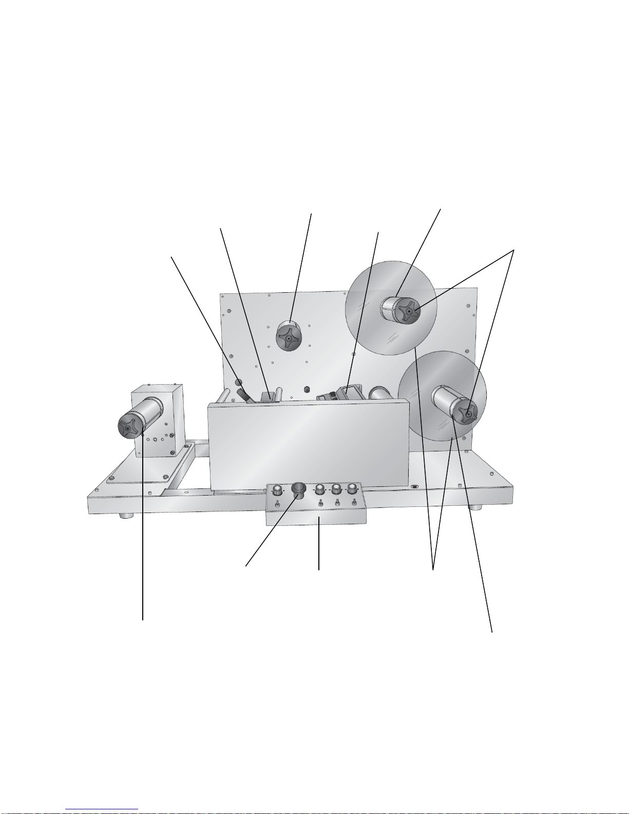
Section 2.3: Indentifying the Parts
FX1000 Overview
Nip Point
Take Up Mandrel
Unwinder / Supply Mandrel
Control Panel
Nip Lever
Slitter Station Core Engagement Knobs
Waste Matrix
Take Up Mandrel
(Weeder)
Media Guides
Upper Take Up Mandrel
(Optional)
Emergency Stop Button

9
Section 3 Run a Job
Section 3.1: Load a Printed Roll
1. On the unwinder/supply mandrel loosen the core engagement knob and remove the
remaining portion of the previous roll, if any.
2. Place the new roll on the unwinder/supply mandrel. Push it back until it touches the core
stop.
3. Be sure that the edge of the media corresponds with the edge of the core. If the media is
coning in or out you will want to attempt to straighten the media on the core. If the core is
shorter than the media width, pull the roll out so that the edge of the media is even with
the core stop. If the core is wider than the media you may need to adjust the guide
collars (Section 3.6) to accommodate the altered position of the web.
4. Turn the core engagement knob clockwise to lock the roll in place.
Core Stop
Unwinder
Knob
10
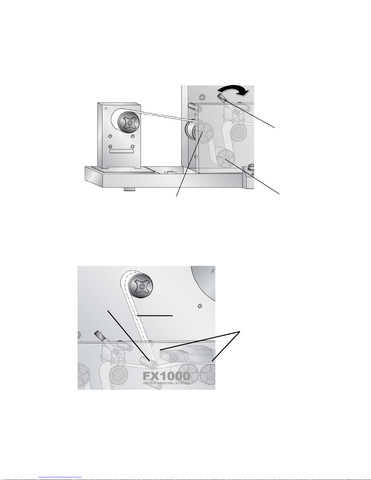
Section 3.2 Set Up the Weeder
1. Push the Nip Lever into the “Nip Open” position.
2. Feed the media OVER the first guide roller and UNDER the second guide roller.
3. Continue feeding the media through the nip point.
4. Once you reach the peel roller, peel the matrix from the liner.
5. Place an empty core on the Matrix mandrel and tighten the core engagement knob.
6. Pull the matrix from the liner and attach it to the Weeder. Manually turn the mandrel
one full revolution.
Matrix
Peel
Roller
Slitter Station
Nip Lever
First Guide Roller Second Guide Roller
Table of contents
Other Primera Industrial Equipment manuals


