PrimeVOLT PV-3000S-V User manual

1
Your PV Inverter Professional
PrimeVOLT
SINGLE PHASE ON-GRID PV INVERTER
PV-3000S-V/PV-3600S-V/PV-5000S-V/PV-5000S-HV
2
Installation & Operation Manual
Version 0.0 Nov. 2019 Printed on Recycled Pap

2
Contents
1Safety Precautions................................................................ 5
1.1 Personnel Safety................................................................................................................................... 5
1.2 The PV Inverter Protection............................................................................................................... 5
1.3 Installation Safety ................................................................................................................................ 5
1.4 Electrical Connections........................................................................................................................ 5
1.5 Operating and Commissioning ..................................................................................................... 6
1.6Maintenance.......................................................................................................................................... 6
1.7 Additional Information...................................................................................................................... 6
2Overview of the Inverter....................................................... 7
2.1 Functional Models............................................................................................................................... 7
2.2 Network Application .......................................................................................................................... 7
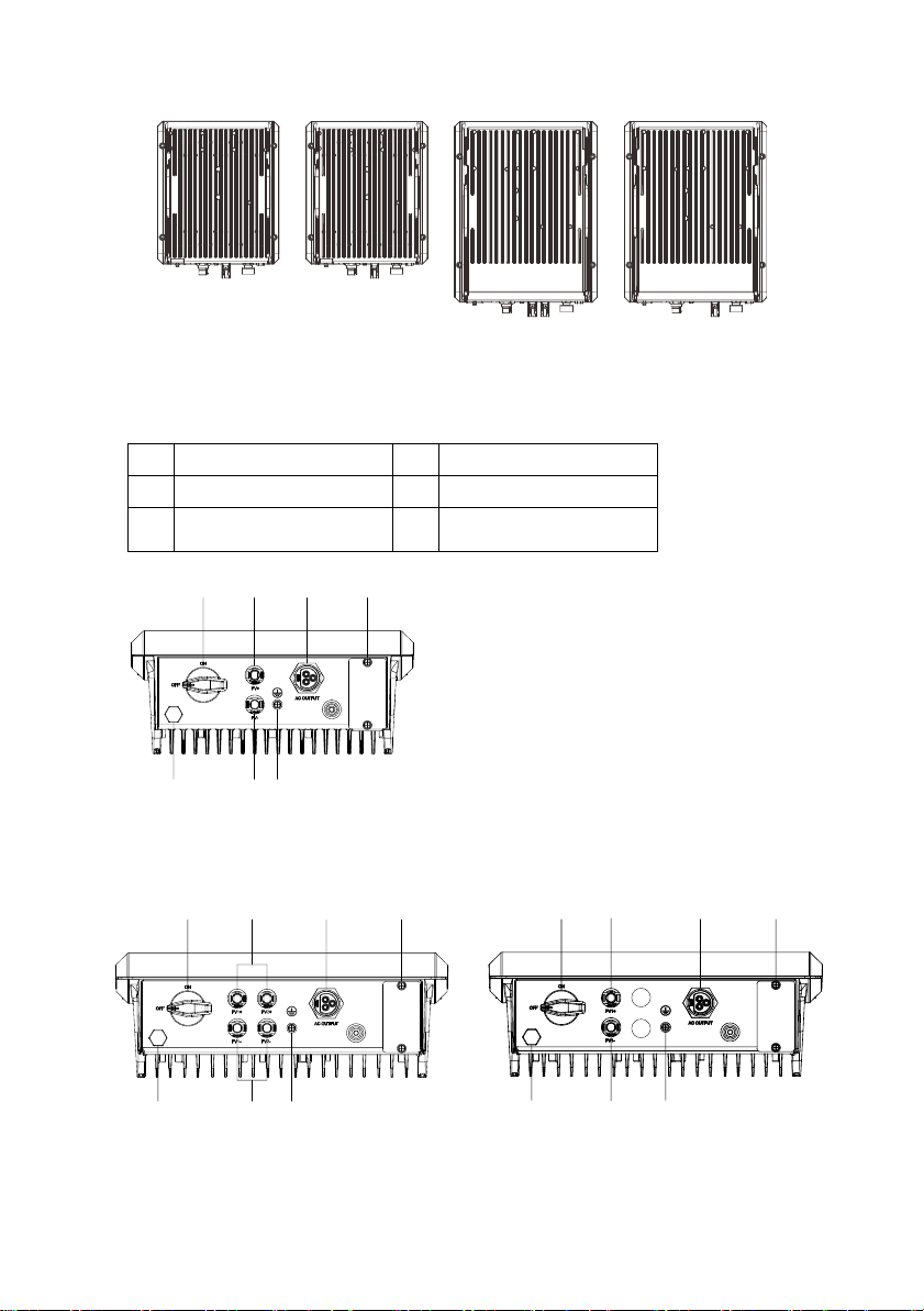
2.3 Outline and Dimensions ................................................................................................................... 8
2.4 Working Process ................................................................................................................................10
3Storage............................................................................... 11
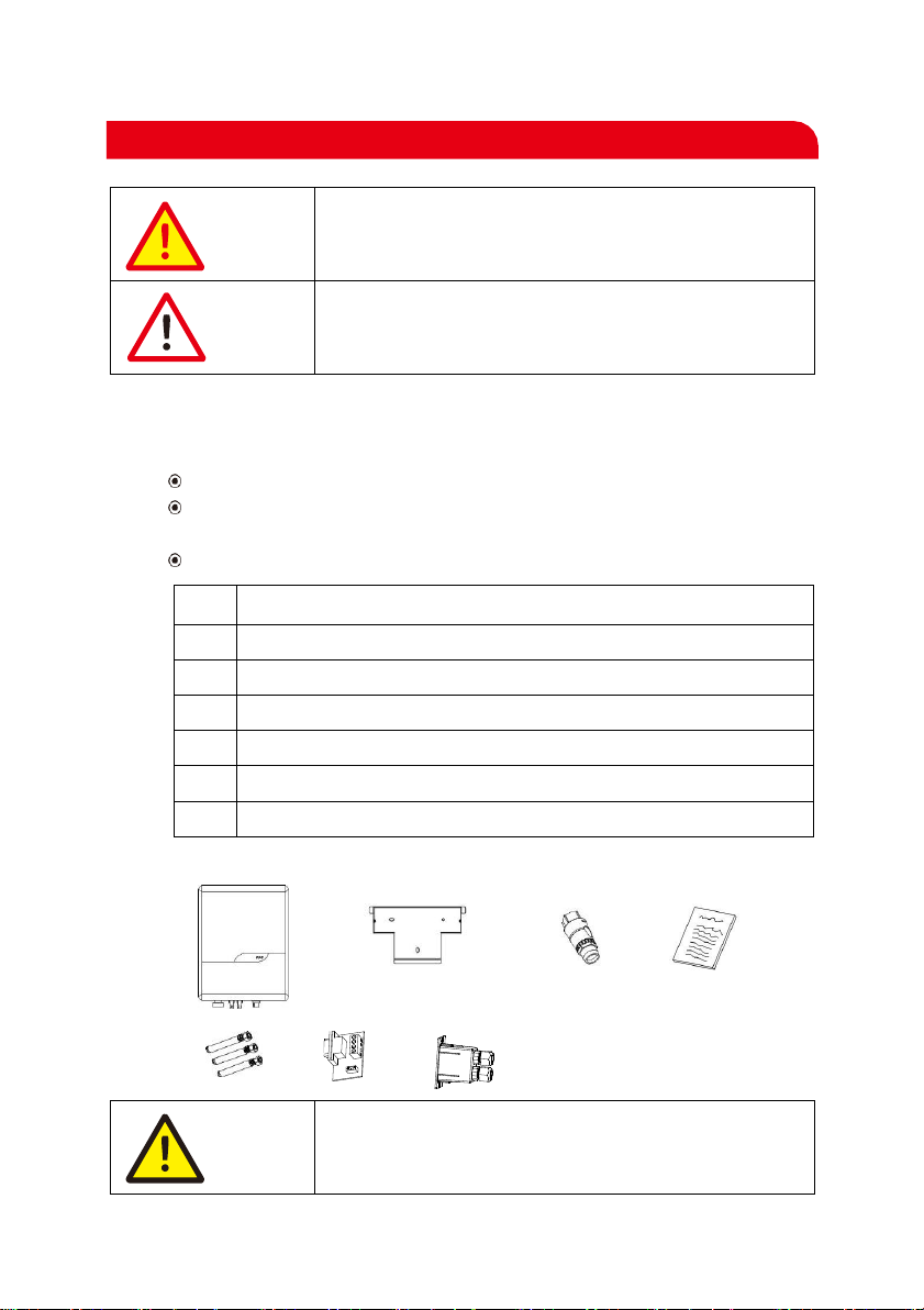
4Installation ......................................................................... 12
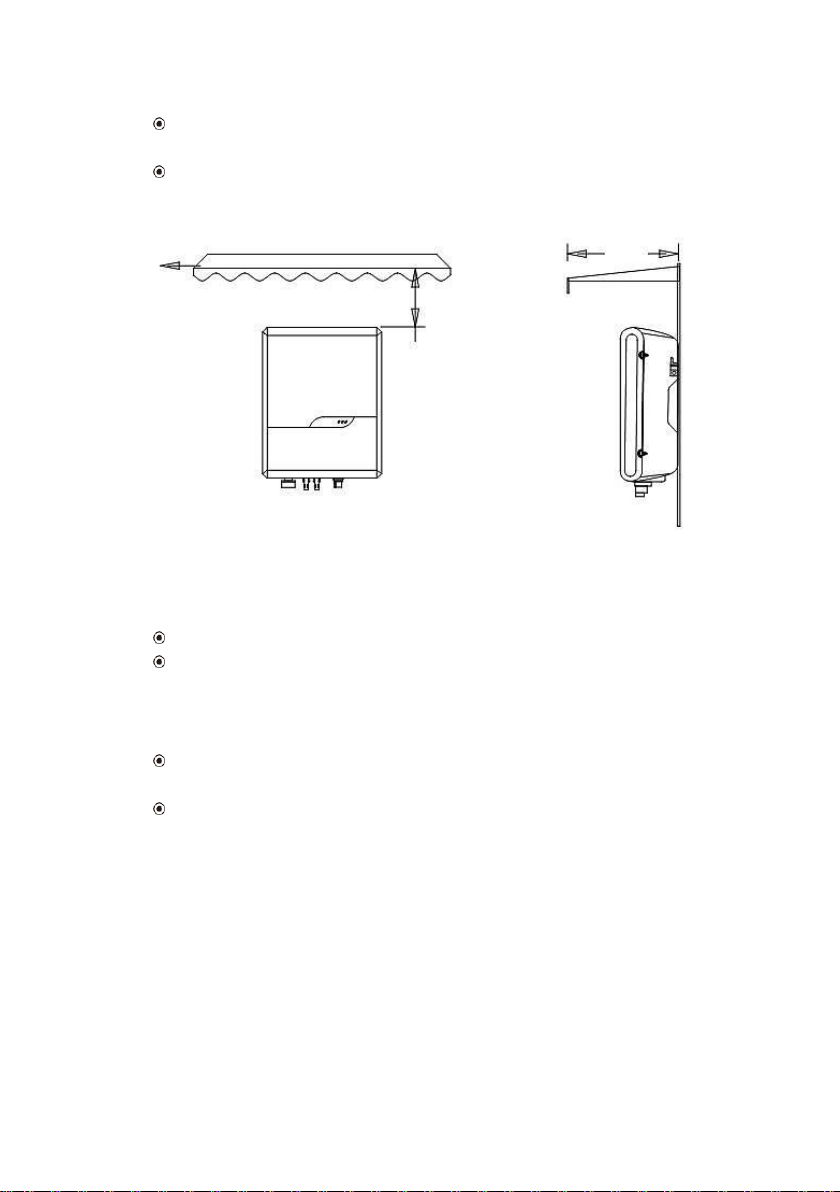
4.1 Determining the Installation Position.......................................................................................14
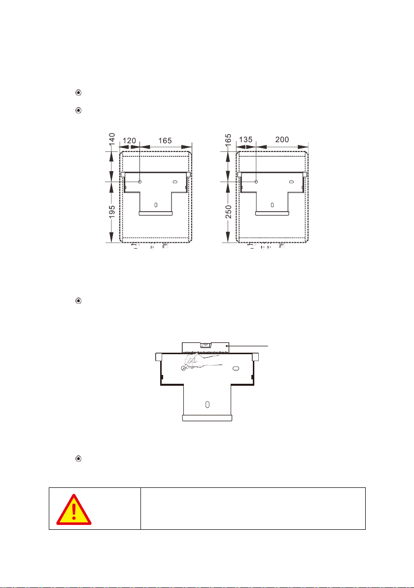
4.2 Installing a Mounting bracket kit................................................................................................19
4.3 Installing the Inverter .......................................................................................................................20
5Electrical Connections......................................................... 21
5.1 Connecting Protection Ground(PGND) Cables.....................................................................21
5.2 Connecting AC Output Cables.....................................................................................................22
5.3 Connecting the PV Strings.............................................................................................................24
5.4 Connecting Communications Cables........................................................................................28
5.5 Installation Verification ...................................................................................................................32
6System Operation............................................................... 33
7User Interface..................................................................... 34
8Maintenance ...................................................................... 35
9Warranty Information......................................................... 38
10 Disposal of the inverter....................................................... 38
11 Technical Specifications ...................................................... 39

3
Forward
Grid-tied string inverter
PV-3000S-V
PV-3600S-V
PV-5000S-V
PV-5000S-HV
This user manual is intended for photovoltaic (PV) inverter operating personnel and qualified
electrical technicians.
This user manual is subject to change (specific please in kind prevail) without prior notice. The
latest version of user manual and other more information about the product are available from
www.primevolt.com, and/or by consulting your dealer.
For more product information, please visit PrimeVOLT website or contact with our sales
representatives.
Thanks you so much for your choosing, the latest generation of grid-tied PV Strings
inverter (hereinafter referred to as the inverter) designed and developed by
PrimeVOLT.
This user manual introduces the inverter in terms of its installation, electrical
connections, operation, commissioning, maintenance, and troubleshooting. Please
read through the manual carefully before installing and using the inverter, and keep
the manual well for future reference.
Application Model
Intended Audience
Notes

4
Safety symbols used in this manual, which highlight potential safety risks and important safety
information, are listed as follows:
Symbol
Description
DANGER
Indicates an imminently hazardous situation which, if not
correctly followed, will result in serious injury or death.
WARNING
Indicates a potentially hazardous situation which, if not
correctly followed, could result in serious injury or death.
CAUTION
Indicates a potentially hazardous situation which, if not
correctly followed, could result in moderate or minor injury.
NOTICE
Indicates a potentially hazardous situation which, if not
correctly followed, could result in equipment failure to run,
or property damage.
NOTE
Calls attention to important information, best practices and
tips: supplement additional safety instructions for your
better use of the PV inverter to reduce the waste of your
resource.
Symbol Conventions

5
Before beginning your journey, please read these safety precautions in User Manual carefully.
1.1 Personnel Safety
The PV inverter must be installed, electronically connected, operated and maintained
through specially trained technician;
The qualified technician must be familiar with the safety regulations of electrical
system, working process of PV power generation system, and standards of local power
grid;
The technician must read through this User Manual carefully and master it before any
operation.
NOTICE
As soon as receiving the PV inverter, please check if it is
damaged during its transportation, If yes, please contact your
dealer immediately.
1.2 The PV Inverter Protection
Do not tamper with any warning signs on the inverter enclosure because these signs
contain important information about safe operation.
Do not remove or damage the nameplate on the inverter’s enclosure because it
contains important product information.
Do not remove the anti-dismantle label on the inverter’s enclosure because it is the
basis for product warranty.
NOTICE
Please read the User Manual carefully before installing the PV
inverter, warranty or liability will be void from PrimeVOLT if
damage is caused by installation faults.
1.3 Installation Safety
Ensure there is no electronical connections around ports of the PV inverter before
installing;
Adequate ventilation must be provided for inverter installation location. Mount the
inverter in vertical direction, and ensure that no object is put on the heat sink affecting
the cooling. (For details, refer to Chapter 4 Installation)
1.4 Electrical Connections
DANGER
Before installing the inverter, check all electrical ports to ensure
no damage and no short circuit. Otherwise personal casualty and
/or fire will occur.
1 Safety Precautions

6
Input terminals of the PV inverter apply only to input terminals of PV String; do not
connect any other DC source to the input terminals.
Before connecting PV modules, ensure that is its voltages is within the safe range;
when exposed to any sunlight, PV modules can generate high voltage.
All electrical connections must meet the electrical standards of the country or region.
Cables used in electrical connections must be well fixed, good insulation, and with
appropriate specification.
DANGER
While the inverter operating, high voltage can lead to an
electrical shock hazard, and even cause personal casualties.
Therefore, operate the PV inverter strictly according to the
safety precautions in the user manual.
1.5 Operating and Commissioning
Before getting the permission of electrical power sector in the country / region, the
grid-tied PV inverter cannot start generate power.
Follow the procedures of commissioning described in the user manual when
commissioning the PV inverter.
Do not touch any other part’s surface except the DC switch when the PV inverter is
operating; its partial parts will be extremely hot and can cause burns.
DANGER
Power OFF all electrical terminals before the inverter
maintenance; strictly comply with the safety precautions in this
document when operating the inverter.
1.6 Maintenance
For personal safety, maintenance personnel must wear appropriate personal
protective equipment (like insulation gloves and protective shoes) for the inverter
maintenance.
Place temporary warning signs or erect fences to prevent unauthorized access to the
maintenance site.
Follow the procedures of maintenance stipulated in the manual strictly.
Check the relevant safety and performance of the inverter; rectify any faults that may
compromise the inverter security performance before restarting the inverter.
1.7 Additional Information
NOTICE
To avoid any other unforeseeable risk, contact PrimeVOLT
immediately, if there is any issue found during operation.

7
This chapter introduces the inverter and describes its functional model, network application,
appearance, dimensions, and working process etc.
2.1 Functional Models
【Function】
PV-3000S-V/PV-3600S-V/PV-5000S-V/PV-5000S-HV are single-phase grid-tied PV string inverter
(transformer less) that converts the DC power generated by PV strings into AC power and feeds
the power into power grid.
WARNING
The inverter is transformerless. Add an isolation transformer
before grounding the positive/negative terminal of PV modules
(like Thin Film module) for operation.
WARNING
Do not connect PV modules in parallel to several PV inverters
for operation.
2.2 Network Application
【Grid-tied PV Power Systems】
PV-3000S-V/PV-3600S-V/PV-5000S-V/PV-5000S-HV applies to grid-tied PV power systems for
outdoor power stations. Typically, a grid-tied PV power system consists of PV modules, DC
switchboard, grid-tied inverters, AC switchboard, and low-voltage power grid, as shown in Figure
2.1.
Figure 2.1 Grid-tied PV power system
2 Overview of the Inverter
Power Grid
AC Switchboard
Grie-tied PV Inverter
DC Switchboard
PV Modules

8
2.3 Outline and Dimensions
【Dimension】
Figure 2.2 PV-3000S-V/PV-3600S-V dimension (unit: mm)
PV-5000S-V
PV-5000S-HV
Figure 2.3 PV-5000S-V/PV-5000S-HV dimension (unit: mm)
【Outline】
PV-3000S-V
PV-3600S-V
PV-5000S-V
PV-5000S-HV
Figure 2.4 PV-3000S-V/PV-3600S-V/PV-5000S-V/PV-5000S-HV front view

9
PV-3000S-V
PV-3600S-V
PV-5000S-V
PV-5000S-HV
Figure 2.5 PV-3000S-V/PV-3600S-V/PV-5000S-V//PV-5000S-HV rear view
【Overview of Connection Area】
①
DC Switch
④
Communication interface
②
DC (PV) Input connectors
⑤
Vent valve
③
AC Output connector
⑥
External Protection
Ground interface
Figure 2.6 PV-3000S-V/PV-3600S-V bottom view
Figure 2.7 PV-5000S-V bottom view Figure 2.8PV-5000S-HV bottom view
①
②
③
④
⑤
②
⑥
①
②
③
④
①
②
③
④
⑤
⑤
⑥
⑥
②
②

10
2.4 Working Process
【Basic principle Description】
The PV-5000S-V PV inverter with double MPPT input receives inputs from two strings of PV panel
(PV-3000S-V/PV-3600S-V/PV-5000S-HV PV inverter with single MPPT input receives inputs from
only one string of PV panel). Then the inputs are grouped into two independent MPPT routes
inside the inverter to track the maximum power point of the PV panel. The two MPPT power is
then converted into DC Bus, then the DC power is converted to AC power through an inverter
circuit, Finally the AC power is feed to the Power grid. EMI filter is used on both the DC and AC
sides to reduce the electromagnetic interface; Surge protection is supported on AC side.
【Circuit Diagrams】
Figure 2.9 shows the circuit diagram for the PV-3000S-V/PV-3600S-V/PV-5000S-HV PV inverter
with single MPPT input
Figure 2.9PV-3000S-V/PV-3600S-V/PV-5000S-HV Circuit diagram
Figure 2.10 shows the circuit diagram for the PV-5000S-V PV inverter with double MPPT input
Figure 2.10 PV-5000S-V Circuit diagram
EMI
AC
Filter
DC SPS
EMI
DC
Filter
Master
DSP
Slave
DSP
MPPT 1
( DC / DC )
BUS CAPS
Inverter
( DC / AC )
Output Relay
PV1 +
PV1 -
L
N
PE
DC SPS
EMI
DC
Filter
MPPT 1
( DC / DC )
BUS CAPS
Inverter
( DC / AC )
Output Relay
PV1 +
PV1 -
MPPT 2
( DC / DC )
L
N
PE
EMI
AC
Filter
Master
DSP
Slave
DSP
PV2 +
PV2 -

11
【Working Modes】
Three working modes of the inverter are shown as follows: standby, operating, and shutdown.
Table 2.1 shows the conditions for the inverter to switch between working modes.
Table 2.1 Working modes description
Modes
Description
Standby
The PV inverter enters the standby mode when
(1) the input voltage of PV Strings can enable auxiliary power
supply to run, but cannot meet the inverter operation
requirements.
(2) the input voltage of PV Strings can meet the inverter to-start
requirements, but cannot meet its minimum power requirements.
Operating
When the PV inverter is grid-tied and generates electricity, it
(1) tracks the maximum power point to maximize the PV String
output.
(2) converts DC power from PV strings into AC power and feeds the
power to the power grid.
The PV inverter will enter to the shutdown mode if detecting a fault
or a shutdown command)
Shutdown
The PV inverter switches from standby or operating mode to
shutdown mode if detecting a fault or a shutdown command.
The inverter switches from shutdown mode to standby mode if
receiving a Startup command or detecting that a fault is rectified.
The following storage instructions apply if the PV inverter will not be deployed immediately:
Do not unpack the inverter (put desiccant in the original box if the PV inverter is
unpacked).
Store the PV inverter at a temperature range of -40oC to +70oC and with the relative
humidity of 0% to 100% (no condensing).
The PV inverter should be store in a clean and dry place and be protected from dust
and water vapor corrosion.
A maximum of eight layers of inverter (PV-3000S-V/PV-3600S-V), six layers of inverter
(PV-5000S-V/PV-5000S-HV) can be stacked.
Do not position inverter at a front tilt, excessive back tilt, or side tilt, or upside down.
Ensure that qualified personnel inspect and test the inverter before use if it has been
stored for a long time.
3 Storage

12
DANGER
Do not install the inverter on flammable building materials or in
an area that stores flammable or explosive materials.
CAUTION
Do not install the inverter in a place where personnel are likely
to come into contact with its enclosure and heat sinks to avoid
electrical shock / burn.
【Checking the Outer Packing】
When receiving the inverter, check that the packing materials are intact.
After unpacking, check that the deliverables are complete, intact, and consistent with
your order list.
Examine the PV inverter and its fittings for damage such as scraps and cracks.
○
A
Inverter
○
B
Mounting bracket kit
○
C
AC output connectors
○
D
User manual
○
E
Plastic anchors and screws (for fastening mounting bracket to wall)
○
F
RS485 communication card
○
G
RS485 cover
NOTICE
If any damage mentioned above is found, contact the dealer
immediately.
4 Installation
○
E
○
A
○
B
○
C
○
D
○
F
○
G

13
【Moving the inverter】
After checking the outer packing, move the PV inverter to the designated installation
position horizontally. Hold the handles on both sides of the inverter, as shown in
Figure 4.1.
Figure 4.1 Moving the inverter
【Identify the PV Inverter】
After moving the PV inverter from packing box, identify it by reading its nameplate
labeled on the side of the inverter. The nameplate contains important product
information: the model information, communications / technical specifications, and
compliance symbols.
CAUTION
When placing the inverter on the floor horizontally, put foam or
paper under to protect its enclosure.
Figure 4.2 Product labels

14
Compliance and Safety Symbols
Safety symbol
Description
There are residual voltages in the PV inverter. It needs 5
minutes to finish discharge.
The PV inverter must not be touched when in operation. Its
enclosure and heat sinks are extremely hot.
Electrical shock! This part is charged. Only qualified and / or
trained electrical technicians are allowed to perform operations
on the inverter.
Please read the User Manual carefully before installing the PV
inverter.
PV-3000S-V/PV-3600S-V/PV-5000S-V/PV-5000S-HV apply to wall-mounting installation,
as described below in detail.
4.1 Determining the Installation Position
【Basic Requirements】
The inverter is protected to IP65 and can be installed indoors or outdoors.
PV-3000S-V/PV-3600S-V/PV-5000S-V/PV-5000S-HV weight and dimension as shown in
Table 4.1. The installation method and position must be appropriate for the weight
and dimensions of the inverter.
Do not install the inverter in a place where personnel are likely to come into contact
with its enclosure and heat sinks because there parts are extremely hot during
operation.
Do not install the inverter in an area that stores flammable or explosive materials.
Table 4.1 Weight and dimension table
Inverter model
PV-3000S-V/PV-3600S-V
PV-5000S-V/PV-5000S-HV
Weight (kg)
9
13
Dimensions (W x H x D)(mm)
285 x 336 x 125
335 x 426 x 125
【Installation Environment Requirements】
The ambient temperature must be below 45 oC which ensures the inverter’s optimal
operation and extends its service life.

15
The inverter must be installed in a well ventilated environment to ensure good heat
dissipation.
The inverter must be free from direct exposure to sunlight, rain, and snow to extend
its service life. It is recommended that the inverter be installed in a sheltered place. If
no shelter is available, build an awning, as shown in Figure 4.3.
Figure 4.3 Installation environment with awning (unit: mm)
【Carrier Requirements】
The wall must be solid enough to bear the weight of the inverter.
Do not install the inverter on a wall made of gypsum boards or similar materials with
weak sound insulation to avoid noise disturbance in a residential area.
【Installation Space Requirements】
It is recommended that the inverter be installed at eye level to facilitate operation and
maintenance.
Reserve enough clearance around the inverter to ensure sufficient space for
installation and heat dissipation, as shown in Figure 4.4.
≥
1000
≥
500
Awning

16
Figure 4.4 Installation space requirements (unit: mm)
When installing multiple inverter, install them along the same line (as shown in Figure
4.5) if sufficient space is available, and install them in triangle mode (as shown in
Figure 4.6) or in stacked mode (as shown in Figure 4.7) if no sufficient space is
available, The installation modes ensure sufficient space for installation and heat
dissipation.
Figure 4.5 Installation along the same line (unit: mm)

17
Figure 4.6 Installation in triangle mode (unit: mm)
Figure 4.7 Installation in stacked mode (unit: mm)

18
NOTICE
The clearance between multiple inverters must be increased to
ensure proper heat dissipation when they are installed in a hot
area.
【Installation Mode Requirements】
Install the inverter upright or at a maximum back tilt of 15 degrees to facilitate heat dissipation.
Below are some correct / wrong installation modes, as shown in Figures 4.8&4.9.
The correct installation mode
Figure 4.8 The correct installation modes
The wrong installation mode
Figure 4.9 The wrong installation modes
NOTICE
The wrong installation will lead to failure of the inverter
operation.

19
4.2 Installing a Mounting bracket
Before installing the inverter, secure the shipped mounting bracket kit to a wall.
Step 1 : Move out the mounting bracket kit from the packing case.
Step 2 : Determine the positions for drilling holes (as shown in Figure 4.10) using the
mounting bracket kit.
Figure 4.10 Determine the positions for drilling holes (unit: mm)
Step 3 : Level the hole positions using a level, and mark the hole positions using a
marker (as shown in Figure 4.11).
Figure 4.11 Mark the hole positions using a marker
Step 4 : Drill holes using a hammer drill and install expansion bolts, as shown in Figure
4.12.
DANGER
Before drilling the hole on the wall, ensure no damage on the
electric wire and / or water pipe inside the wall.
PV-3000S-V/PV-3600S-V
PV-5000S-V/PV-5000S-HV
Level ruler

20
Drill a hole in a marked position to a depth of 60mm using a hammer drill with a
Ф10mm bit.
Partially tighten an expansion bolt, vertically insert it into the hole, and knock
the expansion bolt completely into the hole using a rubber mallet.
Figure 4.12 Punch holes and install expansion(unit: mm)
Step 5 : Fixed the mounting bracket kit.
Align the mounting bracket kit with the holes, insert expansion bolts into the holes through
the mounting bracket kit, and tighten the expansion bolts to a torque of 2-2.5 N.m using a
torque wrench, as shown in Figure 4.13.
Figure 4.13 Installing the mounting bracket kit
4.3 Installing the Inverter
Follow below procedures:
Step 1 : The installer to hold the handle at both sides of the inverter and then lift and
stand the inverter.
Step 2 : Mount the inverter on the mounting bracket kit and keep them aligned with
Ø10,drilling depth:60mm
Punch holes
Install expansion bolts
torque : 2-2.5N.m
This manual suits for next models
3
Table of contents
Other PrimeVOLT Inverter manuals

PrimeVOLT
PrimeVOLT V-3000N-V User manual

PrimeVOLT
PrimeVOLT PV-5000T-U User manual

PrimeVOLT
PrimeVOLT PV 2KTL-S1/G2P User manual

PrimeVOLT
PrimeVOLT PV 7KTL-D1P User manual

PrimeVOLT
PrimeVOLT PV T U Series User manual

PrimeVOLT
PrimeVOLT PV-3000N-V User manual

PrimeVOLT
PrimeVOLT PV-5000W-V User manual

PrimeVOLT
PrimeVOLT PV 4K6HB-60 User manual

PrimeVOLT
PrimeVOLT PV 5KTL-D3/G2 User manual

PrimeVOLT
PrimeVOLT PV2KTL-S1/G2P User manual